Table of Contents
Advertisement
Quick Links
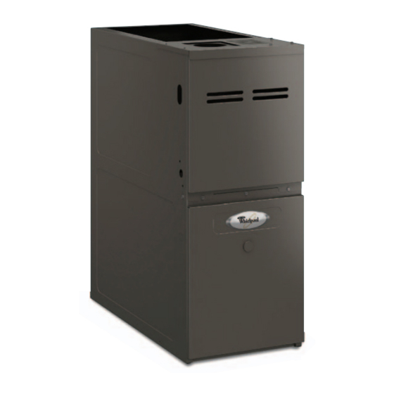
80% SINGLE-STAGE MULTISPEED GAS FURNACE
GAS FURNACE SAFETY................................................................2
INSTALLATION REQUIREMENTS ................................................4
Tools and Parts ............................................................................4
Electrostatic Discharge (ESD) ......................................................4
Location Requirements ................................................................4
Installation Configurations ...........................................................7
Ductwork Requirements ..............................................................8
Electrical Requirements ...............................................................8
Gas Supply Requirements ...........................................................9
Venting Requirements..................................................................9
INSTALLATION INSTRUCTIONS ................................................10
Inspect Shipment .......................................................................10
Plan Vent System .......................................................................10
Install Ductwork..........................................................................14
Filter Specifications....................................................................15
Make Electrical Connections .....................................................16
Electronic Air Cleaner.................................................................18
Make Gas Connections..............................................................18
Start-Up Procedure and Adjustment .........................................22
ATTENTION INSTALLATION PERSONNEL
As a professional installer, you have an obligation to know the product better than the customer. This includes all
safety precautions and related items. Prior to actual installation, thoroughly familiarize yourself with this instruction
manual. Pay special attention to all safety warnings. Often during installation or repair, it is possible to place
yourself in a position which is more hazardous than when the unit is in operations.
Remember, it is your responsibility to install the product safely and to know it well enough to be able to instruct a
customer in its safe use. Safety is a matter of common sense...a matter of thinking before acting. Most dealers have
a list of specific good safety practices...follow them.
The precautions listed in this installation manual are intended as supplemental to existing practices. However, if
there is a direct conflict between existing practices and the content of this manual, the precautions listed here take
precedence.
Placeholder
Whirlpool
®
Model
WFM18, WFD18
WPIO-359B
INSTALLATION INSTRUCTIONS
Table of Contents
®
Whirlpool
14610 Breakers Drive
Jacksonville, Florida 32258
Complete Installation..................................................................26
Furnace Shutdown .....................................................................26
SEQUENCE OF OPERATION ......................................................27
Power Up....................................................................................27
Cooling Mode .............................................................................27
Fan Only Mode ...........................................................................27
OPERATIONAL CHECKS.............................................................28
Burner Flame ..............................................................................28
Auxiliary Limit Control ................................................................28
Circulator Blower Speed ............................................................28
MAINTENANCE ............................................................................31
Annual Inspection.......................................................................31
Filters ..........................................................................................31
TROUBLESHOOTING ..................................................................32
Resetting from Lockout..............................................................34
ASSISTANCE OR SERVICE .........................................................36
Accessories ................................................................................36
Home Cooling and Heating
Advertisement
Table of Contents

Related Manuals for Whirlpool WFM18


Summary of Contents for Whirlpool WFM18
-
Page 1: Table Of Contents
The precautions listed in this installation manual are intended as supplemental to existing practices. However, if there is a direct conflict between existing practices and the content of this manual, the precautions listed here take precedence. Placeholder ® Whirlpool Home Cooling and Heating Whirlpool ® Model 14610 Breakers Drive WFM18, WFD18 Jacksonville, Florida 32258 WPIO-359B... -
Page 2: Gas Furnace Safety
GAS FURNACE SAFETY Recognize this symbol as a safety precaution. Please adhere to the following warnings and cautions when installing, adjusting, altering, servicing or operating the furnace. CAUTION WARNING Goodman 9 Hazards or unsafe practices could result in property Hazards or unsafe practices may result in property damage, product damage, severe personal injury or death. - Page 3 WARNING WARNING Possible property damage, personal injury or death due If the information in these instructions is not followed to fire, explosion, smoke, soot, condensation, electrical exactly, a fire or explosion may result causing property shock or carbon monoxide may result from improper damage, personal injury or loss of life.
-
Page 4: Installation Requirements
Additional Safety Considerations WARNING This furnace is approved for Category I venting only. Provisions must be made for venting combustion products Heating unit should not be utilized without reasonable, outdoors through a proper venting system. The length of the routine inspection, maintenance and supervision. If the flue pipe could be a limiting factor in locating the furnace. - Page 5 Your unit model type determines which installation procedures The furnace heat exchanger, components, duct system, air must be used. For WFM18 models, you must follow instructions for horizontal left, horizontal right or upflow installations only. filters and evaporator coils are thoroughly cleaned following WFM18 furnaces are not approved for downflow installations.
- Page 6 If the furnace is used in connection with a cooling unit, install WARNING the furnace upstream or in parallel with the cooling unit. Premature heat exchanger failure will result if the cooling unit Goodman 50 is placed ahead of the furnace. To prevent possible equipment damage, property damage, personal injury or death, the following bullet points must If the furnace is installed in a residential garage, position the...
-
Page 7: Installation Configurations
For installations above 7,000 ft (2,133.6 m), refer to your local Installation Clearances and Accessibility distributor for required kit(s). Manifold Unobstructed front clearance of 24" (61 cm) for servicing is Pressure recommended. Pressure High Switch Clearances to Combustibles—in. (cm) Altitude Orifice Stage Stage... -
Page 8: Ductwork Requirements
Furnace Suspension 6. After it has been determined that each appliance connected to the venting system properly vents when tested as outlined If you are suspending the furnace from the rafters or joists, use a ³⁄₈" (1 cm) threaded rod and 2" x 2" x ³⁄₈" (5.1 cm x 5.1 cm x 1 cm) above, return doors, windows, exhaust fans, fireplace dampers and any other gas burning appliance to their angle iron as shown below. -
Page 9: Gas Supply Requirements
The line voltage supply should be routed through a readily Existing Venting Systems accessible disconnect located within sight of the furnace. A junction box on the furnace side panel is provided for line voltage connections. See the Wiring Connection Diagram in When an existing furnace is removed or replaced, the original the “Troubleshooting”... -
Page 10: Installation Instructions
INSTALLATION INSTRUCTIONS The minimum vent diameter for the Category I venting system is Inspect Shipment as shown in the Minimum Vent chart. This furnace is shipped in one package, completely assembled Minimum Vent and wired. The indoor thermostat and accessories are shipped in a separate carton when ordered. - Page 11 11. Reconnect the induced draft blower power leads. NOTE: If the wires are not long enough, pull extra wire from the wire bundle in the blower compartment. 12. Reconnect the flue pipe and the pressure switch tubing. Ensure that all wires and the pressure switch tubing are at least 1"...
- Page 12 Termination 10 ft (3 m) or Less From Ridge, Wall or Parapet Proper chimney Line, terminate with termination? listed vent cap (Check 1) (Fix 1) Chimney channel free of solid and Change venting liquid fuel arrangements appliances? (Fix 2) (Check 2) Rebuild crown Crown in good (Fix 3)
- Page 13 Check 2—Any Solid or Liquid Fuel Appliances Vented into The surfaces of the liner must be physically sound. If gaps or This Chimney Channel holes are present, the metal liner must be removed and replaced (Fix 4—Relining). Finally, confirm that the metal liner is the correct Solid fuel appliances include fireplaces, wood stoves, coal size for the appliances to be installed.
-
Page 14: Install Ductwork
In some cases, a shorter extension above the roof may be Heavier gauge 300 and 400 series stainless steel liners were possible with a liner than would be required with a masonry developed for use with oil or solid fuel appliances. They are chimney. -
Page 15: Filter Specifications
When the furnace is used in connection with a cooling unit, the Installation with Return Ducts furnace should be installed in parallel with or on the upstream side of the cooling unit to avoid condensation in the heating A return air duct system is recommended. If the furnace is element. -
Page 16: Make Electrical Connections
Horizontal Installations Thermostat Filters must be installed in either the central return register or in Install a room thermostat according to the instructions furnished the return air ductwork. with it. Select a location on an inside wall that is not subject to drafts, direct sunshine or other heat sources. - Page 17 1. Measure resistance between the neutral (white) connection Junction Box Relocation and one of the burners. 2. Resistance should measure 10 ohms or less. This furnace is equipped with a blower door interlock switch WARNING which interrupts unit voltage when the blower door is opened for servicing.
-
Page 18: 115-Volt Line Connection Of Accessories-Electronic Air Cleaner
24VAC Humidifier 115-Volt Line Connection of Accessories— Electronic Air Cleaner The yellow wire connected to the induced draft blower pressure switch is powered anytime the pressure switch is closed and provides 24VAC humidifier control. WARNING 1. Remove the yellow wire. 2. - Page 19 Contact your distributor for a tabular listing of appropriate Pressure 0.5 psig or less and pressure drop of 0.3" W.C.; Based manufacturer’s kits for propane gas and/or high altitude on 0.60 Specific Gravity Gas installations. The indicated kits must be used to ensure safe and Btu/h Furnace Input proper furnace operation.
- Page 20 General Furnace Layout Check for leaks using an approved chloride-free soap and water solution, an electronic combustible gas detector or other approved testing methods. WARNING Goodman 72 To prevent property damage or personal injury due to fire, the following instructions must be performed regarding gas connections, pressure testing, location of shutoff valve and installation of gas piping.
- Page 21 Complete information regarding tank sizing for vaporization, Propane Gas Installation—Typical recommended regulator settings, and pipe sizing is available from most regulator manufacturers and propane gas suppliers. Since propane gas will quickly dissolve white lead and most standard commercial compounds, special pipe dope must be used.
-
Page 22: Start-Up Procedure And Adjustment
Propane Gas Piping Chart II Tubing Size, O.D. Type L Nominal Pipe Size Schedule 40 Pipe or Tubing ³⁄₈ ¹⁄₂ ⁵⁄₈ ³⁄₄ ⁷⁄₈ ¹⁄₂ ³⁄₄ Length—ft (m) 1¹⁄₈ 1¹⁄₄ 1¹⁄₂ 100 (30.5) 125 (38.1) 150 (45.7) 200 (61) 250 (76.2) Data in accordance with NFPA pamphlet Number 54. - Page 23 White-Rodgers Model 36G22 Gas Control Valve 10. Measure the gas supply pressure with burners firing. Adjust supply pressure using the Inlet Gas Supply Pressure chart. If supply pressure reading differs from the chart, make necessary adjustments to pressure regulator, gas piping size, etc., and/or consult with the local gas utility.
- Page 24 White-Rodgers 36G54 Valve Connected to Manometer NOTE: If measuring gas pressure at the drip leg on the Honeywell VR9205 gas control valve, a field-supplied hose barb fitting must be installed prior to making the hose connection. If using the inlet pressure boss on the White- Rodgers 36G54 gas control valve, then use the 36G Valve Pressure Check Kit.
- Page 25 17. Turn on the gas supply to the furnace at the manual gas WARNING shutoff valve external to the furnace. 18. Reconnect all electrical power to the system. HIGH VOLTAGE! 19. Close thermostat “R” and “W” contacts to provide a call for heat.
-
Page 26: Complete Installation
15. Remove the regulator cover screw from the high (HI) outlet Temperature Rise Measurement pressure regulator adjust tower and turn the screw clockwise Rise = Supply air temperature - Return air temperature to increase the pressure or counterclockwise to decrease pressure. -
Page 27: Sequence Of Operation
SEQUENCE OF OPERATION Furnace operates; integrated control module monitors safety Power Up circuits continuously. If low-stage delay period expires, control will shift operation The normal power up sequence is as follows: from low-stage heating mode operation to high-stage heating 115 VAC power applied to furnace. mode operation. -
Page 28: Operational Checks
OPERATIONAL CHECKS This furnace is equipped with a PSC circulator blower motor. This WARNING blower provides ease in adjusting blower speeds. Refer to the Blower Performance Data chart for proper selection of heating To avoid personal injury or death due to electrical shock, and cooling speeds. - Page 29 Blower Performance Data CFM and Temperature Rise vs. External Static Pressure External Static Pressure (Inches Water Column) Tons AC at Model—Heating Motor 0.5" Speed as Shipped Speed Rise CFM Rise CFM Rise CFM Rise CFM Rise CFM CFM CFM WFM180453A*** High 1,521 1,466...
- Page 30 1,587 1,537 1,492 1,445 1,368 1,287 1,472 1,454 1,404 1,366 1,326 1,300 1,228 1,139 WFM18 CFM and Temperature Rise vs. External Static Pressure External Static Pressure (Inches Water Column) Tons AC at Model—Heating Motor 0.5" Speed as Shipped Speed CFM Rise CFM Rise CFM Rise CFM Rise CFM Rise CFM Rise CFM Rise CFM Rise...
-
Page 31: Maintenance
WFM18 CFM and Temperature Rise vs. External Static Pressure External Static Pressure (Inches Water Column) Tons AC at Model—Heating Motor 0.5" Speed as Shipped Speed CFM Rise CFM Rise CFM Rise CFM Rise CFM Rise CFM Rise CFM Rise CFM Rise... -
Page 32: Troubleshooting
Flame Sensor (Qualified Servicer Only) CAUTION Under some conditions, the fuel or air supply can create a nearly invisible coating on the flame sensor. This coating acts as an Goodman 59 Label all wires prior to disconnection when servicing insulator causing a drop in the flame sense signal. If the flame controls. - Page 33 Problem LED Code Fault/Cause Solution Furnace fails to operate None No 115-volt power to furnace, or no Verify that there is 115-volt power to the 24-volt power to integrated control furnace and 24-volt power to integrated Integrated control module module. control module diagnostic LED provides no signal...
-
Page 34: Resetting From Lockout
Problem LED Code Fault/Cause Solution Induced draft blower and 5 flashes Flame sensed with no call for heat. Correct short at flame sensor or in flame circulator blower runs sensor wiring. Short to ground in flame sense circuit. continuously. No furnace operation. - Page 35 WFM18, WFD18 Wiring Diagram WARNING HIGH VOLTAGE! Disconnect ALL power before servicing. Multiple power sources may be present. Failure to do so may cause property damage, personal injury or death. Integrated Humidifier Control Module XFMR (6) GND (8) 24 VAC...
-
Page 36: Assistance Or Service
If you need further assistance, you can write to the below address with any questions or concerns: Accessories ® Whirlpool Home Cooling and Heating To order accessories, contact your Whirlpool ® Home Cooling and 14610 Breakers Drive Heating dealer. Jacksonville, FL 32258 Please include a daytime phone number in your correspondence.