Advertisement
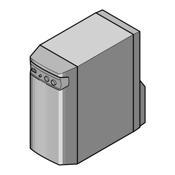
POWERED SUBWOOFER
S-W100S
THIS MANUAL IS APPLICABLE TO THE FOLLOWING MODEL(S) AND TYPE(S).
Model
Type
S-W100S
‡
MYXMA
‡
MLXMA/E
‡
SDXMA1/E
CONTENTS
1. SAFETY INFORMATION .................................... 2
2. EXPLODED VIEWS AND PARTS LIST ............. 3
3. SCHEMATIC DIAGRAM ..................................... 6
4. PCB CONNECTION DIAGRAM ......................... 8
5. PCB PARTS LIST ............................................. 10
6. ADJUSTMENT .................................................. 11
PIONEER ELECTRONIC CORPORATION
PIONEER ELECTRONICS SERVICE, INC. P.O. Box 1760, Long Beach, CA 90801-1760, U.S.A.
PIONEER ELECTRONIC (EUROPE) N.V. Haven 1087, Keetberglaan 1, 9120 Melsele, Belgium
PIONEER ELECTRONICS ASIACENTRE PTE. LTD. 501 Orchard Road, #10-00 Wheelock Place, Singapore 238880
PIONEER ELECTRONIC CORPORATION 1998
Power Requirement
AC220-230V
AC220-230V
AC110-115V/120-127V/220-230V/240V
4-1, Meguro 1-Chome, Meguro-ku, Tokyo 153-8654, Japan
The voltage can be converted by the following method.
With the voltage selector
7. GENERAL INFORMATION .............................. 11
7.1 DIASSEMBLY ............................................ 11
7.2 BLOCK DIAGRAM ..................................... 12
................................................................... 13
T-ZZR AUG. 1998 Printed in Japan
ORDER NO.
RRV2012
Advertisement
Table of Contents

Summary of Contents for Pioneer S-W100S
-
Page 1: Table Of Contents
PIONEER ELECTRONICS SERVICE, INC. P.O. Box 1760, Long Beach, CA 90801-1760, U.S.A. PIONEER ELECTRONIC (EUROPE) N.V. Haven 1087, Keetberglaan 1, 9120 Melsele, Belgium PIONEER ELECTRONICS ASIACENTRE PTE. LTD. 501 Orchard Road, #10-00 Wheelock Place, Singapore 238880 PIONEER ELECTRONIC CORPORATION 1998... -
Page 2: Safety Information
, a l w a y s c o n s u l t t h e c u r r e n t P I O N E E R Service Manual. A subscription to, or additional copies Also test with plug reversed of, PIONEER Service Manual may be obtained at a (Using AC adapter Earth nominal charge from PIONEER. -
Page 3: Exploded Views And Parts List
Bottom Protector SHA2127 Polyethylene Bag E11- 024 RCA Plug cord (L=3.0m) SDE1028 (2) CONTRAST TABLE S-W100S/MYXMA, MLXMA/E and SDXMA1/E are constructed the same except for the following: Part No. Symbol and Description Mark Remarks MYXMA type MLXMA/E type SDXMA1/ E type... - Page 4 See Contrast table (2) Screw BPZ30P100FZK KBA1047 Screw KBA1048 (2) CONTRAST TABLE S-W100S/MYXMA, MLXMA/E and SDXMA1/E are constructed the same except for the following: Part No. Symbol and Description Mark Remarks MYXMA type MLXMA/E type SDXMA1/ E type CS ASSY...
- Page 5 Heatsink BRKT (A) SNB1061 Screw BYC40P160FZB Heatsink BRKT (B) SNB1062 (2) CONTRAST TABLE S-W100S/MYXMA, MLXMA/E and SDXMA1/E are constructed the same except for the following: Part No. Symbol and Description Mark Remarks MYXMA type MLXMA/E type SDXMA1/E type AC Power Coed...
-
Page 6: Schematic Diagram
S-W100S 3. SCHEMATIC DIAGRAM 3.1 JACK , CONT, POWER, LED, TRN. SEC and TRN. PRI ASSEMBLIES JACK ASSY JK4 : AKX-507A VOLTAGE SELECTOR 240V 120 – 127V 110 – 115V 220 –230V TO CN11 FU3: SEK1008 / SDXMA1/E T5A/250V SEK1005/MYXMA T1.6A/250V /MLXMA/E... - Page 7 S-W100S Note : When ordering service parts, be sure to refer to "EXPLODED VIEWS and PARTS LIST" or "PCB PARTS LIST". CONT ASSY SWITCHES: SW2: POWER SW / OFF SMF1001(F1:2/2) TO CN12 POWER ASSY...
-
Page 8: Pcb Connection Diagram
S-W100S 4. PCB CONNECTION DIAGRAM SIDE A JACK ASSY JACK ASSY SWZ1011-A AC POWER CORD CN13 CN14 LED ASSY CONT ASSY CN11 PW SW + POWER SW PW SW - NOTE FOR PCB DIAGRAMS: 1. Part numbers in PCB diagrams match those in the schematic diagrams. - Page 9 S-W100S SIDE A POWER ASSY IC 7 IC 5 CN19 IC 6 LDB+ STGD -15V +15V TRN. PRI ASSY TRN. SEC POWER TRANSFORMER ASSY (SNP1078-A)
-
Page 10: Pcb Parts List
S-W100S 5. PCB PARTS LIST NOTES : ÷ Parts marked by “ NSP ” are generally unavailable because they are not in our Master Spare Parts List. ÷ The mark found on some component parts indicates the importance of the safety factor of the part. -
Page 11: Adjustment
S-W100S 6. ADJUSTMENT There is no information to be shown in this chapter. 7. GENERAL INFORMATION 7.1 DISASSEMBLY Grill ASSY Slit ¶ GRILL ASSY SECTION Remove the Grill Assy. Insert a screwdriver into the slit under the Grill Assy to pry open the front grill gradually and uniformly. -
Page 12: Block Diagram
S-W100S 7.2 BLOCK DIAGRAM... -
Page 13: Panel Facilities And Specifications
S-W100S 8. PANEL FACILITIES AND SPECIFICATIONS 7 PANEL FACILITIES ∫¿ˆ¥YY∫ POWERED SUBWOOFER REAR PANEL 6 Line Level Input terminal (LINE LEVEL INPUT) FRONT PANEL Connects to the stereo amplifier’s SUBWOOFER PRE-OUT terminal, with the specially provided RCA plug cord. 1 Power switch (POWER) When pressed, power is turned ON;...


