Fujitsu ARYG45LMLA Service Manual
Duct type (50hz)
Hide thumbs
Also See for ARYG45LMLA:
- Service manual (28 pages) ,
- Design & technical manual (343 pages) ,
- Service manual (85 pages)
Advertisement
SPLIT TYPE
AIR CONDITIONER
DUCT TYPE (50Hz)
Indoor unit
ARYG45LMLA AOYG45LETL
CONTENTS
SPECIFICATIONS. . . . . . . . . . . . . . . . . . .
DIMENSIONS. . . . . . . . . . . . . . . . . . . . . .
REFRIGERANT SYSTEM DIAGRAM. . . .
CIRCUIT DIAGRAM . . . . . . . . . . . . . . . . .
INDOOR PCB CIRCUIT DIAGRAM . . . . .
ERROR DETECTION . . . . . . . . . . . . . . .
PARTS (INDOOR UNIT) . . . . . . . . . . . .
PARTS (OUTDOOR UNIT) . . . . . . . . . .
ACCESSORIES . . . . . . . . . . . . . . . . . . .
Outdoor unit
1
2
3
4
5
8
. . .
14
18
21
24
Advertisement
Table of Contents

Related Manuals for Fujitsu ARYG45LMLA


Summary of Contents for Fujitsu ARYG45LMLA
-
Page 1: Table Of Contents
DUCT TYPE (50Hz) Indoor unit Outdoor unit ARYG45LMLA AOYG45LETL CONTENTS SPECIFICATIONS....DIMENSIONS..... . -
Page 2: Specifications
SPECIFICATIONS ELECTRICAL DATA NOISE LEVEL High Cooling & Heating 42 dB TYPE ARYG45LMLA Medium 38 dB INDOOR UNIT INDOOR UNIT OUTDOOR UNIT AOYG45LETL 32 dB COOLING CAPACITY 12.1 kW Quiet 28 dB 13.3 kW OUTDOOR UNIT 55 dB HEATING CAPACITY... -
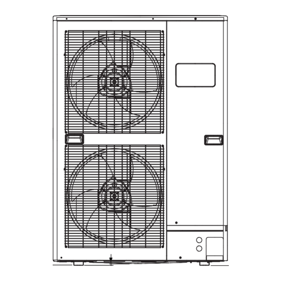
Page 3: Dimensions
DIMENSIONS OUTDOOR UNIT (Unit : mm) INDOOR UNIT 1,177 1,015 1,135 air flow 2013.02.18... -
Page 4: Refrigerant System Diagram
REFRIGERANT SYSTEM DIAGRAM OUTDOOR UNIT INDOOR UNIT Refrigerant Pipe Pressure 15.88mm (5/8") Check Valve 3-way Valve Muffler Pressure Sensor 4-way Valve Heat Heat Check Exchanger Exchanger Valve High Pressure Accumulator Switch Muffler Compressor Refrigerant Pipe 9.52mm (3/8") Strainer Strainer Expansion 3-way Valve Valve Thermistor (Room) -
Page 5: Circuit Diagram
OUTDOOR UNIT HIGH PRESSURE SWITCH CN101 WHITE BLACK THERMISTOR WHITE CN61 ( OUTDOOR TEMP. ) WHITE BLACK WHITE BLACK THERMISTOR ( PIPE TEMP. ) WHITE CIRCUIT DIAGRAM BLACK WHITE CN63 WHITE MAIN PCB THERMISTOR CN401 BLACK CN40 WHITE ( PIPE - MID. TEMP. ) BLACK WHITE INDICATOR PCB... -
Page 6: Indoor Pcb Circuit Diagram
INDOOR PCB CIRCUIT DIAGRAM THERMISTOR BLACK B02B-XASK-1-A BLACK ( ROOM TEMP. ) WHITE B02B-XAYK-1-A YELLOW THERMISTOR CONTROL UNIT GRAY B5P-SHF-1AA B02B-XAKK-1-A GRAY ( PIPE TEMP. ) WHITE BLACK EZ-01229HSE 15-1 15-2 CN15 15-3 B06B-XASK-1-A 15-4 15-5 WHITE 15-6 2(N) 13-1 13-2 CN13 13-3... - Page 7 INDOOR UNIT MAIN PCB K06AK-120WHSE-C1 R1 - R3 B02B-XASK-1-A 1SS355 10k <1/10W> x 3 THERMISTOR ( ROOM TEMP. ) I C8 FLOAT SWITCH 13.5V NJM7812 B03B-PASK-1 <1/10W> B02B-XAYK-1-A 1.0k B03B-XARK-1-A <F> <1/10W> <1/10W> DC SUPPLY 1.0k 49.9k 0.01 1.0k B02B-XAKK-1-A <F>...
- Page 8 NORMAL COIL CN108 B2P3-VH-B R103 340V D108 13.5V D2FL20U <RS-2W> T101 C108 ZFT22B03-C 4700p <FNS> C113 R111 I C26-14 1000/ R104 <1/10W> 330k <2W> D102 1SR139-600 C114 F101 0.01 3.15A <KH> C109 250V D107 220p C115 Q101 D106 RD16 D101 <B>...
-
Page 9: Outdoor Pcb Circuit Diagram
OUTDOOR PCB CIRCUIT DIAGRAM INVERTER ASSEMBLY EZ-0121HHUE EMI FILTER RFC-13 F103 F104 W100 EMI FILTER AC250V 30A POWER SOURCE UL1015 AC250V 3.15A ZCAT2132-1130 AWG12 AC230V BLACK W102 UL1015 50Hz TM101 AWG12 UL1015 W101 ORANGE AWG12 WHITE FILTER PCB INDOOR UNIT UL1015 W103 UL1015... - Page 10 OUTDOOR UNIT MAIN PCB - 1 K10BS-1203HUE-C1 C167, C168 R163 340V 330p <CH> <1/10W> 12V-2 D200 L152 D3F60 BLm31PG121 C152 D153 3-1747052-4 220/ RF101L2S YELLOW C214 D203 D231 AC I N L155 R219, R220 2200p 1SS355 RF301B2S 1.8k <1/4W> <D> D204 UDZS8.2B R231...
- Page 11 OUTDOOR UNIT MAIN PCB - 2 K10BS-1203HUE-C1 CN12 B02B-XAKK-1-A C802 L800 15V-2 BLACK 15V-2 P_EX_OUT1 340V Q801 CN800 BL02Rn1 <B> EX. OUT 1 DTA143EUA I C10-7 B6P-VH-B D801 uLN2003 WHITE R800 RD24FM FTR-F3 <1/10W> BLm18AG601 DC FAN MOTOR 1 C800 P_FM1_PWM R801 CN13...
- Page 12 OUTDOOR UNIT TRANSISTOR PCB ( I P M ) K10AY-1003HUE-TR0 C209 - C211, C221 C222 C302 0.1 <F> 100/ L300 <F> BL02Rn1 TM303 C332 TM101 86028 D307 86028 C161 RD24FM <F> <X7R> I PM-G TM102 TM304 86028 BLACK 86028 D100 LL25XB60 I C301 TM305...
- Page 13 OUTDOOR UNIT POWER SUPPLY PCB K10BR-1000HUE-FL0 JM100 - JM102 TM103 86028 W111 ORANGE W112 ORANGE TM100 86028 VA100, VA101 FH106 FH107 K100 L101 L102 L100 470V <TNR> H-0017-2 x 2 DW12D1-O (M) RCH3818-022PF07 n200500K RCH3818-022PF07 W100 W102 ORANGE BLACK C104 C106 F103 0.022...
- Page 14 OUTDOOR UNIT CAPACITOR PCB K05FB-1000HUE-P0 WHITE YELLOW C200 - C203 R200 660/ 220k 450V <2W> BLUE VIOLET POWER_G OUTDOOR UNIT INDICATOR PCB K10BC-1000YUE-D0 D401 SLR-325 <ORANGE> D402 SLR-325 <ORANGE> D403 SLR-325 <ORANGE> ( CN401-1 ) D404 SLR-325 <ORANGE> ( CN401-2 ) D405 SLR-325 ( CN401-3 ) <ORANGE>...
-
Page 15: Error Detection
ER R OR D ETEC TION Receiver unit Receiver unit Wired Wired OPERATION TIMER ECONOMY remote Description OPERATION TIMER ECONOMY remote Description INDOOR UNIT lamp lamp lamp lamp lamp lamp control control (green) (orange) (green) (green) (orange) (green) and WIRED REMOTE CONTROL Discharge temp. - Page 16 OUTDOOR UNIT Indicator PCB LEDs Buttons ERROR DETECTION Display when an error occurs. PUMP PEAK POWER ERROR DOWN NOISE MODE (L1) (L2) (L3) (L4) (L5) (L6) Blink (Hi speed) Check that the “ERROR” LED blinks, then press the [Enter] button once. For details, refer to the following table.
-
Page 17: Test Run
OUTDOOR UNIT TEST RUN Before the test run, refer to he figure and check the following items. Setting method Is the outdoor unit securely installed? Turn on the power of the outdoor unit and enter standby mode. Have you performed gas leakage inspection? PUMP PEAK (Connection joints of various pipes (flang connection, brazing)) -
Page 18: Pump Down
OUTDOOR UNIT PUMP DOWN Procedure WARNING (1) Check the 3-way valves (both the liquid side and gas side) are opened. Never touch electrical components such as the terminal blocks except the button on (2) Turn the power on. the display board. It may cause a serious accident such as electric shock. PUMP PEAK During the pump-down operation, make sure that the compressor is turned off before... -
Page 19: Parts (Indoor Unit)
PARTS INDOOR UNIT Ref. Description Part number Intake Cover Sub Assy 9374512010 Main Panel Sub Assy 9374511013 Drain Pan Sub Assy 9374513017 Evaporator Total Assy 9374517251 Seal Panel Sub Assy 9374515011 Outlet Panel Sub Assy 9374510016 Intake Frame Assy 9374216017 Cabinet L Sub Assy 9374509010 Cabinet R Sub Assy... - Page 20 INDOOR UNIT Ref. Description Part number Base Sub Assy 9374504015 Casing A 9374233014 Casing B 9374234011 Sirocco Fan Assy 9356531046 Fan Motor 9603213015 Panel (Control Box) 9374210015 2012.04.11...
- Page 21 INDOOR UNIT Control unit Ref. Description Part number Main PCB 9709245040 Power Supply PCB 9707398359 Terminal 3P 9703345012 Terminal 3P 9306489045 Reactor Assy 9707457018 Remote Control 9318593013 Room Thermistor 9703299025 Pipe Thermistor 9703297021 2012.04.11...
-
Page 22: Parts (Outdoor Unit)
PARTS OUTDOOR UNIT Ref. Description Parts number Ref. Description Parts number Top Panel Sub Assy 9374417056 Motor DC Brushless 9602843039 Front Panel Sub Assy 9374414109 Propeller Fan Assy 9366378020 Sevice Panel Sub Assy 9374415090 Condenser A Sub Assy 9374420261 Emblem Rear 9351355005 Condenser B Sub Assy 9374422081... - Page 23 OUTDOOR UNIT Control box Ref. Description Parts number Main PCB 9708690148 9708678016 Indicator PCB 9900203023 Terminal 9708688015 Filter PCB 9704265012 Thermistor 9707257083 Capacitor PCB 9900624019 Choke Coil 9707592016 ACTPM Transistor PCB 9708647043 Heat Sink 9380358008 Outdoor Thermistor 9900210069 Thermistor Assy (CN63) 9900599027 Thermistor Assy (CN62) 9900598013...
- Page 24 OUTDOOR UNIT Ref. Description Parts number Ref. Description Parts number 3-way Valve Assy 9379079006 4-way Valve Assy 9374425235 3-way Valve Assy 9379077002 Discharge Pipe Assy 9371581248 Compressor 9810153005 Pressure Switch 9900186012 Accumulator 9379014021 Check Joint Assy 9372802038 Expansion Valve Coil 9970096044 Union joint Assy 9379068000...
-
Page 25: Accessories
A C C ESSOR IES INDOOR UNIT Name and Shape Q'ty Application Part number Hanger For suspending the 9356563009 indoor unit from ceiling Special nut A 313005446653 (large flange) Special nut B 313005446759 (small flange) Coupler heat For indoor side pipe joint insulation (large) (gas pipe) 9378173569... - Page 26 OPTIONAL PARTS Parts name and model name Application For air conditioner operation Wired remote control UTY-RNNYM For air conditioner operation Simple remote control UTY-RSNYM Remote sensor unit Room temperature sensor UTY-XSZX External connect kit For control input/output port UTD-ECS5A ( x 1 ) ( x 2 ) ( x 1 ) ( x 2 )
- Page 27 1301G4159...