Table of Contents
Advertisement
CIRCUIT DESCRIPTIONS
REPAIR & ADJUSTMENTS
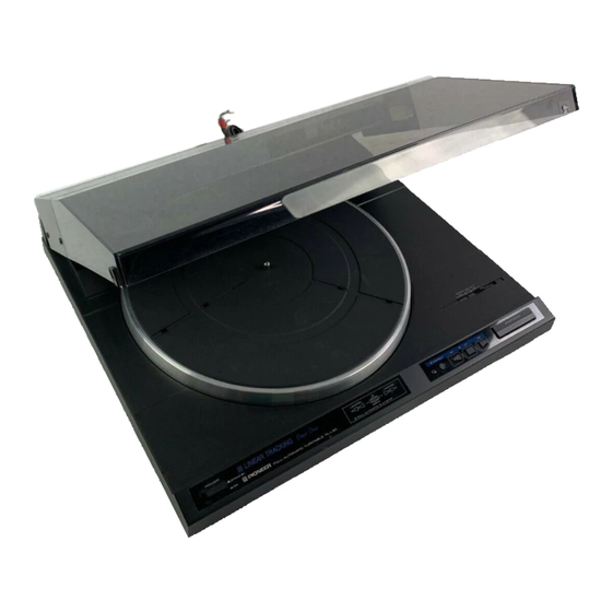
STEREO TURNTABLE
PL-L50
MODEL PL-L50 COM ES IN SEVEN VERSIONS DIS T INGU ISHED AS FOLLOWS:
Type
KU
AC120V only
KUT
AC120V only
KCT
AC120V only
HEM
AC220V, 240V (switchable)
HB
AC220V, 240V (switchable)
s
AC110V, 120V, 220V, 240V (switchable)
SIG
AC110V, 120V, 220V, 240V (switchable)
• This service manual is applicable to the KU, KUT, KCT, HB, HEM, Sand S/G types.
• As to the KUT, KCT, HEM, HB, Sand S/G types please refer to pages 47 - 48.
• Ce manual d'instruction se refere au mode de reglage, en fran�ais.
• Este manual de servicio trata del metodo de ajuste escrito en espanol.
CONTENTS
1. SAFETY INFORMATION ................. 2
2. SPECIFICATIONS ...................... 3
3. FRONT PANEL FACILITIES ............... 4
4. BLOCK DIAGRAM ..................... 5
5. CIRCUIT DESCRIPTIONS ................. 7
6. DISASSEMBLY . . . . . . . . . . . . . . . . . . . . . . . 17
7. PARTS LOCATIONS ................... 20
8. EXPLODED VIEW AND PARTS LIST ........ 22
9. PACKING . . . . . . . . . . . . . . . . . . . . . . . . . . . 25
PIONEER ELECTRONIC CORPORATION
PIONEER ELECTRONICS (USA] INC.
PIONEER ELECTRONIC (EUROPE] N.V.
PIONEER ELECTRONICS AUSTRALIA PTV. LTD.
O,f}PIONEER'
------
Voltage
P.O. Box 1760, Long Beach, California 90801 U.S.A.
TEL: (BOOJ 421-1404, [BOOJ 237-0424
Keetberglaan 1. 2740 Beveren, Belgium TEL: 03/775·28·08
178-184 Boundary Road, Braeside, Victoria 3195, Australia
TEL: (03) 580-9911
--
-
- -
--
Remarks
U.S.A. model
U.S.A. model without cartridge
Canada model without cartridge
European continent model
United Kingdom model
General export model
U.S. Military model
10. P .C . BOARDS CONNECTION DIAGRAM ..... 26
11. SCHEMATIC DIAGRAM ................. 29
12. ELECTRICAL PARTS LIST. . . . . . . . . . . . . . . 32
1� ADJUSTMENTS ...................... 34
R�GLAGE .......................... 36
AJUSTE ............................ 38
14. TROUBLESHOOTING . . . . . . . . . . . . . . . . . . 40
S AND S/G TYPES . . . . . . . . . . . . . . . . . . . . . 47
4-1, Meguro 1-chome, Meguro-ku, Tokyo 153, ...Japan
ORDER NO.
ARP-685-0
FZ © NOV. 1984 Printed in Japan
Advertisement
Table of Contents

Related Manuals for Pioneer PL-L50


Summary of Contents for Pioneer PL-L50
-
Page 1: Table Of Contents
O,f}PIONEER' CIRCUIT DESCRIPTIONS ------ ORDER NO. REPAIR & ADJUSTMENTS ARP-685-0 STEREO TURNTABLE PL-L50 MODEL PL-L50 COM ES IN SEVEN VERSIONS DIS T INGU ISHED AS FOLLOWS: Type Voltage Remarks AC120V only U.S.A. model AC120V only U.S.A. model without cartridge AC120V only... -
Page 2: Safety Information
For the latest 2-wire cord information, always consult the current PIONEER Service A lso test with Manual. A subscription to, or additional copies of, PIONEER plug reversed Earth Service Manual may be obtained at a nominal charge from... -
Page 3: Specifications
Signal-to-Noise-Ratio ....More than 78 dB (DIN-Bl S,S/Gmodels ..........9W Dimensions ....... 420 (W) x 108 ( H) x 365 ( D) mm (with Pioneer cartridge model PC-300T) 16-1/2 (W) x4-1/4 (H) x 14-3/8 (D) in. Tonearm Weight ............ 4.8 kg/11 lb Type ........ -
Page 4: Front Panel Facilities
PL-LSO 3. FRONT PANEL FACILITIES -"'---- [UPI indicator lights: The tonearm rises ( the stylus moves away from the record). [UPI indicator goes out: The tonearm descends (the stylus is lowered onto the record). @ START/STOP switch Depress this switch when starting auto play or when stop ping play. -
Page 5: Block Diagram
PL-L50 4. BLOCK DIAGRAM RESET Cl PHONO MOTOR CIRCUIT DRIVING HALL- AMP CONVERTER .DRIVING RESET CIRCUIT SAMPLE ,S HOL D CIRCUIT VOLTAGE REGULATOR BUFFER TIMING Cl RCUIT PHASE COMPARATOR LOCK INDICATOR + B 1 (12Vl VCC2 CIRCUIT +B2(5Vl POWER SUPPLY CIRCUIT... - Page 6 ARM RESET SWITCH PD6033 RESET ADDRESS SENSOR CIRCUIT S/ S -0 � ADDRESS I> <l SIZE DETECTOR CIRCUIT �AUTO 17 SIZE 30 SIZE (1/2) 33 /45 PH- MOTOR DRIVER I> 06 (REP) + 82 REP LED <l D71UP) EV I EV 2 COVER 0/C DETECTOR SWITCH...
-
Page 7: Circuit Descriptions
5. CIRCUIT DESCRIPTIONS M54547P 5.1 CIRCUIT DESCRIPTIONS 5.1.1 Address Sensor Circuit VR201 The address sensor is located on the mechanism base Tracking sensor unit. It detects the position of the tonearm and sends ad gain ADJ dress pulses to the control IC as the tonearm moves. The address sensor is made up of an internal schmitt trigger drive motor circuit photo interrupter and a slit wheel which is syn... - Page 8 5.1.3 Elevation and Tonearm Circuits • Tonearm drive The tonearm drive motor and EV solenoid are controlled The tonearm drive is controlled by input to 03 pin 4, by commands from the control IC (01 ), which also con pin 5, and pin 15. Their truth values are shown in Fig. 5-4 trols the horizontal and vertical movement of the tonearm.
- Page 9 5.1.4 Seize Detector Circuit • When there is a 17 cm Record The size detector is made up to three slits for detecting When the 17 cm record size slits are covered by a record, 30 cm records, three slits for detecting 17 cm records, and 081 turns off, and 080 remains off.
- Page 10 5. 1.5 Phono Motor Circuit current produces a magnetic field in the drive coil, and the polarity of the coil and the polarity of the rotor attract and The phono motor of this player uses magnetism along repel each other causing the motor to start turning. the outside edge of the drive magnet to determine its rpm When the motor starts turning, the signal (approximately value.
- Page 11 ""J-l- + -,w..-------------------0 331/3 : H (OPEN) 11-13\I 45 ; L �----------------------------------- ---0:��� T: � (OPENJ Fig. 5-9 Phono Motor Circuit (Approximately 0.3V p-p) 3.6V ,C\_ Pin 6 l.7V 3.7V Pin 8 Pin 16 2.3 V Pin 10 3.6V 7.1 V Pin 15 Fig.
- Page 12 IC (PD6033) terminal descriptions Terminal name Description S ymbol display EX ta I Ceramic oscil- Internal clock oscillator external circuit terminal lator "3M Hz" Xtal Reset CPU initial reset input � Normally "H" I> � Tonearm motor drive output (toward outside edge) <l Tonearm motor drive output (toward center) �...
- Page 13 17cm EP Fully automatic playing Place 17cm record on Cover closed Cover open turntable. START/STOP � " Fully automatic Power on playing starts. Initial reset Turntable o Tone a rm at rest (33rpm) o Phono motor stationary � ov r e c se d o Speed switch set to A U TO position.
- Page 15 Timing chart 17cm EP fully automatic operation 1 cycle -C,- Speed switch set to AUTO --------- - - -[QJ £ c:;:i � _j_� "' R�o,dsi� Lead-in Turntable Lead-in Tonea, Arrival at 17cm rpms begins lowering position down 17cm ) detection I>...
-
Page 18: Disassembly
6.1 UNIT DISASSEMBLY 6.2 CARRIAGE REMOVAL 1. Open the dust cover and remove the rubber sheet and 1. Remove the fixer from the carriage and the wire from turntable. the pulley. (See Figure 6.2) 2. Close the dust cover and gently turn the unit over. 2. - Page 19 6.3 REPLACING THE CARRIAGE WIRE 3. Holding both the wire and the worm wheel, connect the wire to the wire guard and attach the worm wheel to • After assembling the carriage and tonearm assemblies in the mechanism base. the opposite order of the previous section, replace the ©...
- Page 21 Top View .-- -- -- -- --------- Slide switch * * Belt- ------------ --, PEB-097 PSH-007 ----- -• Solenoid assembly PXB-392 ** Driving motor----- PXM-137 Mechanism base board assembly PWX-083 ------* Tonearm assembly PPD-678 ---- Carriage board assembly PWX-084 ---------Slide knob PAC-215 ------ Function knob (A) Powerknob (A)------...
-
Page 22: Exploded View And Parts List
8. EXPLODED VIEW AND PARTS LIST NOTES: • Parts without part number cannot be supplied. • The 6 mark found on some component parts indicates the importance of the safety factor of the part. Therefore, when replacing, be sure to use parts of identical designation. - Page 23 � · ,3f®\-y" � ) 15...
- Page 24 7�...
-
Page 25: Packing
9. PACKING --+---4 -· Parts List of Packing Part No. Description Mark PRB-275 Operating instructions PHH-188 Packing case PHA-178 Protector ( L) PHA-179 Protector (R) PNY-198 Packing Screw PBA-178 Carriage clamper PNY-194 Rubber mat assembly PEA-074 Sheet 101. Sheet 102. -
Page 26: Boards Connection Diagram
10. P. C. BOARDS CONNECTION DIAGRAM Ph Tr BOARD UNIT � 81, 82 LEAD-IN STATUS PH101 LEAD-OUT STATUS SOLENOID ASSEMBLY PXB-392 CARRIAGE BOARD ASSEMBLY (PWX-084) PU BOARD UNIT Q8;9 PU CORD ASSEMBLY PDX-016... - Page 28 MOTOR BOARD UNIT (PXM- I 46) Tr BOARD(A) UNIT ( r EIJ POWER TRANSFOMER (OFF) ASSEMBLY PTX-050 �NO , -- - - - (ON) SB : OPEN/CLOSE SWITCH PSG-053 COVER CLOSE : ON , - --+<:>-+--6.._ 0 Hz COVER OPEN : OFF __ R_ E _ D -<r1 POWER CORD ASSEMBLY...
-
Page 29: Schematic Diagram
11. SCHEMATIC DIAGRAM SW BOARD UNIT Tr BOARD ( A) UNIT Tr BOARD CB) UNIT XWS-032 l..RED r:::, �7�S=IT-;-, jRE;U:;;;;;-·1 j;E�O;I ,.; I 11 1 1 AC 120V PSA-008 60Hz &NJM7812A &NJM78 MO!IA POWER CORO ASSEMBLY o..-� � =) = PD E·22J L __ �-----]... - Page 30 NOTE: The indicated semiconductors are representative ones only. Other alternative semiconductors may be used and are listed in the parts list. 1. RESISTORS: Indicated in n, %W, YeW,:t5% to M: M<l, IFI: ,1%, ( GI: ,2%. (K ---1 2. CAPACITORS: CONTROL BOARD UNIT...
-
Page 32: Electrical Parts List
12. ELECTRICAL PARTS LIS T NOTES: • When ordering resistors, first convert resistance values into code form as shown in the following examples. Ex. 1 When there are 2 effective digits (any digit apart from 0), such as 560 ohm and 47k ohm (tolerance is shown by J=5%, and K=10%). - Page 33 SW Board Unit (XWS-032) Motor Assembly (PXM-146) Mark _ S -'- ym _ bo _ l _ & _ D _ es _ c _ r ip _ ti _ o _ n _____ Part No. Mark Symbol & Des c ription Part No.
-
Page 34: Adjustments
13. ADJUSTMENTS 13.2 TRACKING SENSOR GAIN AND OFFSET ADJUSTMENT • Gain Adjustment 1. Remove the dust cover and panel cover. 13.1 TONE ARM ADJUSTMENT 2. Connect a DC voltmeter to CN5 pin 4 (GND) and pin 5 1. With the power ON place a test record (PLS-2001 or (TRKG). - Page 35 13.4 Phono-Motor Speed Adjustment 13.3 TONE ARM HEIGHT ADJUSTMENT 1. Place the strobe sheet on the platter. Turn on the power 1. With the dust cover off, insert two 6mm spacers (one switch and the locate-switch ( <II <II ) to turn the phono each on the right and left) to make it the same as when motor.
-
Page 36: R�Glage
13.REGLAGE 13.2 REGLAGE DU GAIN DU SENSEUR D'ALIGNEMENT ET DU DECENTRAGE • Reglage du Gain 1. Deposer le couvercle anti-poussiere et le couvercle du 13.1 REGLAGE DU BRAS DE PICK-UP panneau. 1. En mettant l'appareil sous tension, placer un disque 2. - Page 37 13.3 REGLAGE DE LA HAUTEUR DU BRAS DE 13.4 REGLAGE DE LA VITESSE DU MOTEUR PICK-UP DU LECTEUR DE DISQUE 1. Avec le couvercle anti-poussiere depose, inserer deux 1. Placer la feu ille stroboscopique sur le plateau. Mettre en pieces d'ecartement de 6 mm (une sur la droite et l'autre service le commutateur d'al imentation et le commutateur sur la gauche) pour retourner a la situation a laquel le le de positionnement ( .,..
-
Page 38: Ajuste
13. AJUSTE 13.2 AJUSTE DE GANANCIA DEL SENSOR DE SEGUIMIENTO Y DE DESCENTRADO • Ajuste de Ganancia 1. Sacar la cubierta para el polvo y la cubierta del panel. 13.1 AJUSTE DEL BRAZO DE FONOCAPTOR 2. Conectar un voltimetro de C.C. al pasador No. 4 (GND) 1. - Page 39 13.4 AJUSTE DELA VELOCIDAD DEL MOTOR 13.3 AJUSTE DE LA ALTURA DEL BRAZO DEL TOCADISCOS DE FONOCAPTOR 1. Con la cubierta para el polvo desmontada, insertar dos 1. Colocar la hoja de estroboscopia sabre el platillo. Encen chavetas de 6mm (una derecha y una a la izquierda) para der el conmutador de alimentaci6n y el conmutador de emular la situaci6n en que la cubierta para el polvo y la colocaci6n (.,..,.
-
Page 40: Troubleshooting
14. TROUBLESHOOTING 14.1 MAIN CHART ----r-- 1 - Start Set speed (rpm) to AUTO and turn the power ON. Check JP1, JP2 and both terminals of C4 and C5 etc. Does the UP LED turn ON? Check the 12V and 5V lines The tonearm returns to the rest and ----... - Page 42 14.4 THE SWITCHES FAIL TO WORK The switches fail to work. With the power off, check whether Faulty switch the switches short out when pushed? Check the patterns from the switches Does the Microcomputer port of the to the 01 switch input port. pressed switch become "L"? Perfrom an LED check 14.5 TRACKING FAILURE...
- Page 43 14.6 TONEARM MOVEMENT The tonearm fails to move. Is approximately 11V being applied Are the motor belt and drive wire to the both terminals of the drive properly attached? motor? With CN3 removed, is the voltage Check connections and soldering up Faulty Does the motor turn when between CN3 (male) pins...
- Page 44 14.7 ELEVATION OPERATION FAILURE Elevation operat on failure Note: The EV UP/ON doesn't work when the tonearm s on the rest. Place a record on the turntable and move the tonearm to the play posit ..c.. -CL.. Does the UP LED go on and Switch failure EV SW? [®�=w.---:-...
- Page 45 14.8 SOUND FAILURE There's no sound. Check the amplifier functions and the speaker and PU cord connections. Check the soldering on PU base board and then check the carriage base board. Check the connections from the cart ridge unit to the PU cord. Check the cartridge.
- Page 46 14.10 SIZE SENSOR CHECK Size sensor check. Check the mechanism base board, Are 0301 and 302 on? R303, 304 and LED for errors. Remove the record and move the tonearm from the rest with the locate switch (turntable rpm). (Using an oscilloscope) are the out - ..._ Check the base 081 and 82 and then ___.
-
Page 47: Supplement For Kut, Kct, Hem, Hb, S And S/G Types
15. SUPPLEMENT FOR KUT, KCT, HEM, HB, S AND S/G TYPES • Model PL-L50/KUT, KCT, HEM and HB are the PL-L50/KU with the exception of this supplement. Contrast of Miscellaneous Parts NOTES: • When ordering resistors, first convert resistance values into code form as shown in the following examples. - Page 48 Power Supply Circuit for HEM and HB types SW BOARD UN IT LINE VOLTAGE XWS-032 SELECTOR � PSB-01 3 LIVE AC 220/240V 50/60 Hz Power Supply Circuit for Sand S/G types POWER TRANSFOR M ER SW BOARD UNIT LINE VOLTAGE ASSEMBLY �...