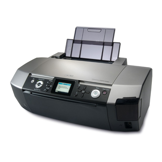
Epson Stylus Photo R340 Service Manual
Color inkjet printer
Hide thumbs
Also See for Stylus Photo R340:
- Printer basics manual (81 pages) ,
- Basic operation manual (40 pages) ,
- Manual (13 pages)
Table of Contents
Advertisement
Advertisement
Table of Contents
Troubleshooting

Related Manuals for Epson Stylus Photo R340


Summary of Contents for Epson Stylus Photo R340
-
Page 1: Service Manual
SERVICE MANUAL Color Inkjet Printer EPSON Stylus Photo R340/350 SEIJ05008... - Page 2 The contents of this manual are subject to change without notice. All effort have been made to ensure the accuracy of the contents of this manual. However, should any errors be detected, SEIKO EPSON would greatly appreciate being informed of them.
- Page 3 REPAIRS ON EPSON PRODUCT SHOULD BE PERFORMED ONLY BY AN EPSON CERTIFIED REPAIR TECHNICIAN. MAKE CERTAIN THAT THE SOURCE VOLTAGES IS THE SAME AS THE RATED VOLTAGE, LISTED ON THE SERIAL NUMBER/RATING PLATE. IF THE EPSON PRODUCT HAS A PRIMARY AC RATING DIFFERENT FROM AVAILABLE POWER SOURCE, DO NOT CONNECT IT TO THE POWER SOURCE.
-
Page 4: About This Manual
Provides preventive maintenance procedures and the lists of C A U T I O N condition that, if not strictly observed, could result in damage to, Epson-approved lubricants and adhesives required for or destruction of, equipment. servicing the product. APPENDIX... - Page 5 Revision Status Revision Issued Date Description September 16, 2005 First Release...
-
Page 6: Table Of Contents
EPSON Stylus Photo R340/350 Revision A CONTENTS Chapter 1 Troubleshooting 2.3.21 Removing the CD-R Guide Assy............84 2.3.22 Removing the Ink System ................ 88 1.1 Overview ......................8 2.3.23 Removing the Front Paper Guide and EJ Roller Assy......91 1.2 Warning/Error Messages and Possible Causes ............. - Page 7 C H A P T E R TROUBLESHOOTING...
-
Page 8: Overview
EPSON Stylus Photo R340/350 Revision A 1.1 Overview Table 1-1. Motor Wire-Wound Resistor Motor Connected Pin No. Check Point Resistance This chapter describes how to troubleshoot problems. Be sure to see the tables PF Motor CN10 Pin 1 and 3 3.0Ω... -
Page 9: Warning/Error Messages And Possible Causes
[BK](T0481) [M](T0483) [C](T0482) [LM](T0486) [LC](T0485) [Y](T0484) NOTE "*" :The ink cartridge codes displayed on the LCD vary according to the model. Stylus Photo R340 : [BK]T0481,[M]T0483,[C]T0482,[LM]T0486,[LC]T0485,[Y]T0484 Stylus Photo R350 : [BK]T0491,[M]T0493,[C]T0492,[LM]T0496,[LC]T0495,[Y]T0494 Troubleshooting Warning/Error Messages and Possible Causes... - Page 10 EPSON Stylus Photo R340/350 Revision A Table 1-3. LCD Error Messages and Possible Causes (continued) LCD Messages Printer Condition Possible Causes Recovery from Errors Reference External device is not connected or media Backup error Occurs in the following conditions: Automatically recovers from the error after a lapse is not inserted.
- Page 11 EPSON Stylus Photo R340/350 Revision A Table 1-3. LCD Error Messages and Possible Causes (continued) LCD Messages Printer Condition Possible Causes Recovery from Errors Reference The CD/DVD guide is open. Close the CDR/DVD guide open Displayed in the following conditions: Automatically recovers from the error after a lapse p.25...
- Page 12 “Borderless expansion” print setting menu. of three seconds. on an edge. NOTE "*" :The ink cartridge codes displayed on the LCD vary according to the model. Stylus Photo R340 : [BK]T0481,[M]T0483,[C]T0482,[LM]T0486,[LC]T0485,[Y]T0484 Stylus Photo R350 : [BK]T0491,[M]T0493,[C]T0492,[LM]T0496,[LC]T0495,[Y]T0494 Troubleshooting Warning/Error Messages and Possible Causes...
-
Page 13: Chapter 1 Troubleshooting
EPSON Stylus Photo R340/350 Revision A 1.3 Troubleshooting Be sure to first check the messages displayed on the LCD or the STM3 screen on a connected computer to identify the cause of the problem quickly. Then troubleshoot the problem following the instructions given in the tables in this section. When any components to be repaired or replaced are found, see Chapter 2 “Disassembly/Reassembly” to correctly reinstall or replace the components. - Page 14 USB cable. During communication error occurs (an error Printer driver 1. Check if the Stylus Photo R340/350 driver is used for 1. Install the Stylus Photo R340/350 printer operation message is displayed on STM3 screen) the print job.
- Page 15 EPSON Stylus Photo R340/350 Revision A Table 1-5. Troubleshooting of Ink-related Errors (Message 1 and 7) based on Observed Symptom Occurrence Timing Symptoms Failed Part Check Point Remedies CR Position • Occurrence An ink-related error occurs when the Ink Cartridge 1.
- Page 16 EPSON Stylus Photo R340/350 Revision A Table 1-6. Troubleshooting of Fatal Errors based on Observed Symptom Occurrence Timing Symptoms Failed Part Check Point Remedies CR Position • Occurrence The CR Motor does not start to operate CR Motor 1. Check if the CR Motor cable is correctly connected to 1.
- Page 17 EPSON Stylus Photo R340/350 Revision A Table 1-6. Troubleshooting of Fatal Errors based on Observed Symptom (continued) Occurrence Timing Symptoms Failed Part Check Point Remedies CR Position • Occurrence The Carriage Unit hits against the Upper Upper Paper Guide 1. Check if the Upper Paper Guide has not come off the 1.
- Page 18 EPSON Stylus Photo R340/350 Revision A Table 1-6. Troubleshooting of Fatal Errors based on Observed Symptom (continued) Occurrence Timing Symptoms Failed Part Check Point Remedies CR Position • Occurrence The Carriage Unit hits against the right Head Cable 1. Check if the Head cable is correctly connected to the 1.
- Page 19 EPSON Stylus Photo R340/350 Revision A Table 1-7. Troubleshooting of Paper Out Error based on Observed Symptom Occurrence Timing Symptoms Failed Part Check Point Remedies CR Position • Occurrence The LD Roller shaft rotates to feed ASF Assy. 1. Check the Hopper if it works properly during feeding 1.
- Page 20 EPSON Stylus Photo R340/350 Revision A Table 1-7. Troubleshooting of Paper Out Error based on Observed Symptom (continued) Occurrence Timing Symptoms Failed Part Check Point Remedies CR Position • Occurrence The PF Motor drive cannot be Shaft Assy. Holder 1. Check if the Extension Spring 0.143 in the clutch 1.
- Page 21 EPSON Stylus Photo R340/350 Revision A Table 1-8. Troubleshooting of Paper Jam Errors based on Observed Symptom Occurrence Timing Symptoms Failed Part Check Point Remedies CR Position • Occurrence Paper feeding operation is performed ASF Assy. 1. Check if the ASF Assy. is properly installed.
- Page 22 EPSON Stylus Photo R340/350 Revision A Table 1-8. Troubleshooting of Paper Jam Errors based on Observed Symptom (continued) Occurrence Timing Symptoms Failed Part Check Point Remedies CR Position • Occurrence Paper is fed into the printer, but it is PE Sensor 1.
- Page 23 EPSON Stylus Photo R340/350 Revision A Table 1-8. Troubleshooting of Paper Jam Errors based on Observed Symptom (continued) Occurrence Timing Symptoms Failed Part Check Point Remedies CR Position • Occurrence Paper edge cannot go through between EJ Frame Assy.* 1. Check if the Star Wheel Holder has not come off.
- Page 24 EPSON Stylus Photo R340/350 Revision A Table 1-8. Troubleshooting of Paper Jam Errors based on Observed Symptom (continued) Occurrence Timing Symptoms Failed Part Check Point Remedies CR Position • Occurrence Top edge of paper cannot be sent to the Upper Paper 1.
- Page 25 EPSON Stylus Photo R340/350 Revision A Table 1-9. Troubleshooting of Errors at Opening the CD/DVD Guide based on Observed Symptom Occurrence Timing Symptoms Failed Part Check Point Remedies CR Position • Occurrence The CD/DVD guide open error occurs at Upper Housing 1.
- Page 26 EPSON Stylus Photo R340/350 Revision A Table 1-9. Troubleshooting of Errors at Opening the CD/DVD Guide based on Observed Symptom (continued) Occurrence Timing Symptoms Failed Part Check Point Remedies CR Position • Occurrence The CD/DVD guide open error occurs at Stacker Lock 1.
- Page 27 EPSON Stylus Photo R340/350 Revision A Table 1-10. Troubleshooting of Name Card Insertion Error based on Observed Symptom Occurrence Timing Symptoms Failed Part Check Point Remedies CR Position • Occurrence The name card insertion error occurs at PE Sensor 1. Check if the PE Sensor cable is correctly connected to 1.
- Page 28 EPSON Stylus Photo R340/350 Revision A Table 1-11. Troubleshooting of CD/DVD Tray Errors based on Observed Symptom Occurrence Timing Symptoms Failed Part Check Point Remedies CR Position • Occurrence A CD/DVD Tray error occurs when CD-R Tray 1. Check if the contact portion of the CDR Tray Sensor on 1.
- Page 29 EPSON Stylus Photo R340/350 Revision A Table 1-11. Troubleshooting of CD/DVD Tray Errors based on Observed Symptom (continued) Occurrence Timing Symptoms Failed Part Check Point Remedies CR Position • Occurrence The CDR Tray center detection CDR Tray 1. Check the white marking on the CDR Tray for any paper 1.
-
Page 30: Troubleshooting By Observed Symptom
EPSON Stylus Photo R340/350 Revision A 1.3.2 Troubleshooting by Observed Symptom Table 1-12. Multi-Feed Occurs with No Error Messages displayed on the LCD or STM3 screen Occurrence Timing Symptoms Failed Part Check Point Remedies CR Position • Occurrence Multiple sheets are always fed at a time ASF Assy. - Page 31 EPSON Stylus Photo R340/350 Revision A Table 1-13. Abnormal Noises are Produced during Operation Occurrence Timing Symptoms Failed Part Check Point Remedies CR Position • Occurrence Printing operations are performed Carriage Unit 1. Check if the CR Guide Shaft is properly lubricated.
- Page 32 EPSON Stylus Photo R340/350 Revision A Table 1-14. Print Quality Problems (continued) Problems Description Failed Part Check Point Remedies • Dot missing Although ink is properly discharged Print Head 1. Check if the printer recovers from the error by the head 1.
- Page 33 EPSON Stylus Photo R340/350 Revision A Table 1-14. Print Quality Problems (continued) Problems Description Failed Part Check Point Remedies • White bands/ Vertical bands (perpendicular to the CR Print Head 1. Print a nozzle check pattern and examine the printout 1.
- Page 34 EPSON Stylus Photo R340/350 Revision A Table 1-14. Print Quality Problems (continued) Problems Description Failed Part Check Point Remedies • White bands/ A vertical (perpendicular to the CR EJ Frame Assy. 1. Check if the Star Wheel Holder has not come off.
- Page 35 EPSON Stylus Photo R340/350 Revision A Table 1-14. Print Quality Problems (continued) Problems Description Failed Part Check Point Remedies • Ink smudges Ink smudges appear on the top and Front Paper Guide 1. Check if any part of the Front Paper Guide Porous Pad is 1.
- Page 36 C H A P T E R DISASSEMBLY AND ASSEMBLY...
-
Page 37: Overview
EPSON Stylus Photo R340/350 Revision A 2.1 Overview Disconnect the power cable before disassembling or assembling W A R N I N G the printer. This chapter describes procedures for disassembling the main components of the Stylus If you need to work on the printer with power applied, strictly follow the instructions in this manual. -
Page 38: Tools
EPSON Stylus Photo R340/350 Revision A 2.1.2 Tools Table 2-2. Work Completion Checklist Classification Item Check Point Status Use only specified tools to avoid damaging the printer. Checked Is the CR Motor at the correct Carriage Table 2-1. Tools temperature? (Not too hot to... -
Page 39: Ensuring The Quality Of Disassembled/Reassembled Printer Mechanism
To ensure the correct position of the Printer Mechanism, it must be checked in X, Y, and Z directions as described below. However, on the other hand, the Stylus Photo R340/350 require to remove the Lower Housing from the Printer Mechanism to replace the Waste Ink Pad or the Ink System. - Page 40 EPSON Stylus Photo R340/350 Revision A Caution on Attaching the ASF Assy., Main Board Assy., and Upper Paper Guide [Purpose] To prevent the Main Frame from deforming due to the force exerted on it during attaching the above three parts.
-
Page 41: Disassembly
EPSON Stylus Photo R340/350 Revision A 2.3 Disassembly The flowchart below lists the step-by-step disassembly procedures. When disassembling each unit, refer to the page number shown in the figure. Start Since a prototype was used to illustrate these C H E C K... -
Page 42: Removing The Paper Support Assy
EPSON Stylus Photo R340/350 Revision A 2.3.1 Removing the Paper Support Assy. Parts/Components must be removed to remove the Paper Support Assy. None Illustration Disassembly Procedure Paper Support Assy. Release the two guide pins ( ) that secure the Paper Support Assy. and remove it. -
Page 43: Removing The Left Housing
EPSON Stylus Photo R340/350 Revision A 2.3.2 Removing the Left Housing Parts/Components must be removed to remove the Left Housing. None Illustration Disassembly Procedure Upper Housing Remove the screw ( ) that secures the Left Housing. Hooked Tab Left Side of... -
Page 44: Removing The Right Housing
EPSON Stylus Photo R340/350 Revision A 2.3.3 Removing the Right Housing Parts/Components must be removed to remove the Right Housing. None Illustration Disassembly Procedure Left Front Side Card Slot Cover Remove the screw ( ) that secures the Right Housing. - Page 45 EPSON Stylus Photo R340/350 Revision A Reattaching the Card Slot Cover Spring Insert the shorter leg of the spring into the groove of the upper guide pin ( ) of the Card Slot Cover, and secure the longer leg of the spring by the hooked tab ( ) on the Right Housing.
-
Page 46: Removing The Panel Board/Lcd Module
EPSON Stylus Photo R340/350 Revision A 2.3.4 Removing the Panel Board/LCD Module Parts/Components must be removed to remove the Panel Board/LCD Module. Illustration (1) None Disassembly Procedure Hooked Tab of the Open the Printer Cover and Stacker Assy. Cosmetic Panel... - Page 47 EPSON Stylus Photo R340/350 Revision A Illustration (2) Release the four tabs ( ) that secure the Panel Board and remove it. Remove the all buttons from the Housing Panel Assy. Panel Board 10. Remove the two screws ( ) that secure the LCD Module.
-
Page 48: Removing The Upper Housing
EPSON Stylus Photo R340/350 Revision A 2.3.5 Removing the Upper Housing Parts/Components must be removed to remove the Upper Housing. Paper Support Assy., Left Housing, Right Housing, Illustration (1) Panel Board Assy. (Panel Board and LCD Module) Disassembly Procedure Printer Cover Acetate Tapes Move the Carriage Unit to its home position. - Page 49 EPSON Stylus Photo R340/350 Revision A Illustration (2) Lift the front right edge of the Upper Housing to release the Optical Tube Sub Slot from the two guide pins ( ) on the Housing Slot. Optical Tube Release the four tabs ( ) that secure the Upper Housing with a flat-blade...
-
Page 50: Removing The Rear Housing
EPSON Stylus Photo R340/350 Revision A 2.3.6 Removing the Rear Housing Parts/Components must be removed to remove the Rear Housing. Paper Support Assy., Left Housing, Right Housing, Illustration Panel Board Assy. (Panel Board and LCD Module), Upper Housing Disassembly Procedure C.B.P 3x8 (4-6kgf.cm) -
Page 51: Removing The Stacker Assy
EPSON Stylus Photo R340/350 Revision A 2.3.7 Removing the Stacker Assy. Parts/Components must be removed to remove the Stacker Assy. Paper Support Assy., Left Housing, Right Housing, Illustration Panel Board Assy. (Panel Board and LCD Module), Upper Housing Disassembly Procedure... -
Page 52: Removing The Front Paper Guide Porous Pads
EPSON Stylus Photo R340/350 Revision A 2.3.8 Removing the Front Paper Guide Porous Pads Parts/Components must be removed to remove the Front Paper Guide Porous Pad. Illustration Paper Support Assy., Left Housing, Right Housing, Panel Board Assy. (Panel Board and LCD Module), Upper Housing Disassembly Procedure Remove the following three pads from the Front Paper Guide Assy. - Page 53 EPSON Stylus Photo R340/350 Revision A Reattaching the Front Paper Guide Support Porous Pad Put the Front Paper Guide Porous Pad under the ribs and be sure that the pad is tightly fitted on the Front Paper Bend the support porous pad along the bend line at a right Guide.
-
Page 54: Removing The Main Board Assy
EPSON Stylus Photo R340/350 Revision A 2.3.9 Removing the Main Board Assy. Parts/Components must be removed to remove the Main Board Assy. Paper Support Assy., Left Housing, Right Housing, Illustration (1) Panel Board Assy. (Panel Board and LCD Module), Upper Housing... - Page 55 EPSON Stylus Photo R340/350 Revision A Illustration (2) Illustration (3) Housing Slot Optical Tube Slot C.B.P 3x8 PG Detector Holder (6-8kgf.cm) Contact Point C.B.S 3x6 (6-8kgf.cm) C.B.S 3x6 (4-6kgf.cm) Positioning Grooves C.B.P 3x8 (6-8kgf.cm) Figure 2-26. Removing the Main Board Assy. (3) Remove the three screws ( ) that secure the Main Board Assy.
- Page 56 EPSON Stylus Photo R340/350 Revision A Set the two positioning grooves ( ) of the Optical Tube Slot Tighten the screws to secure the Main Board Assy. in the order onto the two guide pins. See Figure 2-26. shown in Figure 2-25.
- Page 57 EPSON Stylus Photo R340/350 Revision A Align the Panel FFC and the LCD FFC with the lines marked Whenever the Main Board Assy. is replaced, be sure to perform the A D J U S T M E N T R E Q U I R E D on the side of the Main Board Assy., and secure them with two-...
-
Page 58: Removing The Asf Assy
EPSON Stylus Photo R340/350 Revision A 2.3.10 Removing the ASF Assy. Parts/Components must be removed to remove the ASF Assy. Paper Support Assy., Left Housing, Right Housing, Illustration Panel Board Assy. (Panel Board and LCD Module), Upper Housing, Rear Housing, Main Board Assy. - Page 59 EPSON Stylus Photo R340/350 Revision A Illustration When performing the next step, be careful not to touch the Hopper C A U T I O N Pad with bare hands. Compression Spring 2.51 Hopper Pad Hopper Extension Spring 0.45 Compression Spring 0.31 Figure 2-33.
- Page 60 EPSON Stylus Photo R340/350 Revision A Reassembling the ASF Assy. Reinstalling the ASF Assy. Hitch the L-shaped leg of the Torsion Spring 6.45 to the Attach the Compression Spring 2.51 to the rib ( ) of the shaft of the Paper Back Lever, and hitch the other shorter Hopper and the two ribs ( ) of the ASF Frame, and make leg of the spring to the groove of the ASF Assy.
- Page 61 EPSON Stylus Photo R340/350 Revision A Set the positioning groove of the ASF Assy. onto the guide Tighten the screws in the order shown in Figure 2-31, so as pin. not to trap the PF Motor and PG Motor connector cables under the ASF Assy.
-
Page 62: Removing The Shaft Assy. Holder
EPSON Stylus Photo R340/350 Revision A 2.3.11 Removing the Shaft Assy. Holder Parts/Components must be removed to remove the Shaft Assy. Holder. Paper Support Assy., Left Housing, Right Housing, Illustration Panel Board Assy. (Panel Board and LCD Module), Upper Housing, Rear Housing, Main Board Assy., ASF Assy. - Page 63 EPSON Stylus Photo R340/350 Revision A Illustration (2) Removing the LD Roller Shaft Release the two tabs ( ) that secure the Paper Block and remove it. Paper Block LD Roller Shaft Holder LD Roller LD Roller Shaft Release the two tabs ( ) that secure the LD Roller Shaft and remove it together with the Clutch.
- Page 64 EPSON Stylus Photo R340/350 Revision A Reinstalling the PE Sensor Reinstalling the Clutch Route the PE Sensor connector cable as shown in Figure Attach the Extension Spring 0.143 to the Clutch in the 2-43. Be sure to route the cable under the two ribs of the LD correct orientation as shown in the figure below.
- Page 65 EPSON Stylus Photo R340/350 Revision A Reinstalling the LD Roller Shaft Whenever the LD Roller Shaft is replaced, be sure to apply proper A D J U S T M E N T R E Q U I R E D amount of the G-74 oil to the specified points.
-
Page 66: Removing The Cr Motor
EPSON Stylus Photo R340/350 Revision A 2.3.12 Removing the CR Motor When performing the next step, be careful not to damage the pinion C A U T I O N gear of the CR Motor. Illustration Right Rear Side of the Printer Remove the two screws that secure the CR Motor and remove it. -
Page 67: Removing The Print Head
EPSON Stylus Photo R340/350 Revision A 2.3.13 Removing the Print Head Parts/Components must be removed to remove the Print Head. Paper Support Assy., Left Housing, Right Housing, Illustration Panel Board Assy. (Panel Board and LCD Module), Upper Housing Disassembly Procedure... - Page 68 EPSON Stylus Photo R340/350 Revision A Make sure that the Head Cable is correctly connected to the Print Head. Set the two positioning holes ( ) of the Print Head onto the two guide pins. Positioning Holes Figure 2-52. Reinstalling the Print Head...
-
Page 69: Removing The Upper Paper Guide
EPSON Stylus Photo R340/350 Revision A 2.3.14 Removing the Upper Paper Guide Parts/Components must be removed to remove the Upper Paper Guide. Paper Support Assy., Left Housing, Right Housing, Illustration Panel Board Assy. (Panel Board and LCD Module), Upper Housing, Rear Housing, Main Board Assy., ASF Assy., Shaft Assy. -
Page 70: Removing The Printer Mechanism
EPSON Stylus Photo R340/350 Revision A 2.3.15 Removing the Printer Mechanism Parts/Components must be removed to remove the Printer Mechanism. Paper Support Assy., Left Housing, Right Housing, Illustration (1) Panel Board Assy. (Panel Board and LCD Module), Upper Housing, Rear Housing, Main Board Assy., ASF Assy., Shaft Assy. Holder C.B.S 3x6 (6-8kgf.cm) - Page 71 EPSON Stylus Photo R340/350 Revision A Illustration (2) Release the U-shaped leg of the APG Grounding Spring from the notch of the APG Assy. and release the C-shaped leg of the spring from the notch of the Change Lever Main Frame, then remove the APG Grounding Spring.
- Page 72 EPSON Stylus Photo R340/350 Revision A The correct installation position of the Printer Mechanism is Z Direction ensured by carefully checking the specified points in relation to (Vertical Direction) the Lower Housing. X Direction To ensure the installation accuracy, the position of the Main Frame must be checked in X, Y, and Z directions as described below.
- Page 73 EPSON Stylus Photo R340/350 Revision A After making sure that the Waste Ink Tube is routed under the Lower Waste In Pad, attach the Upper Ink Eject Porous Pad Support to/in the position/orientation as shown in the figure below making it contact with the Waste Ink Tube.
-
Page 74: Removing The Power Supply Assy
EPSON Stylus Photo R340/350 Revision A 2.3.16 Removing the Power Supply Assy. Parts/Components must be removed to remove the Power Supply Assy. Paper Support Assy., Left Housing, Right Housing, Illustration Panel Board Assy. (Panel Board and LCD Module), Upper Housing, Rear Housing, Main Board Assy., ASF Assy., Shaft Assy. -
Page 75: Removing The Waste Ink Pads
EPSON Stylus Photo R340/350 Revision A 2.3.17 Removing the Waste Ink Pads Parts/Components must be removed to remove the Waste Ink Pads. Paper Support Assy., Left Housing, Right Housing, Illustration Panel Board Assy. (Panel Board and LCD Module), Upper Housing, Rear Housing, Main Board Assy., ASF Assy., Shaft Assy. -
Page 76: Removing The Lower Housing
EPSON Stylus Photo R340/350 Revision A 2.3.18 Removing the Lower Housing Parts/Components must be removed to remove the Lower Housing. Paper Support Assy., Left Housing, Right Housing, Illustration Panel Board Assy. (Panel Board and LCD Module), Upper Housing, Rear Housing, Main Board Assy., ASF Assy., Shaft Assy. Holder, Lower Housing Printer Mechanism, Power Supply Assy., Waste Ink Pads, Stacker Assy. -
Page 77: Removing The Apg Assy
EPSON Stylus Photo R340/350 Revision A 2.3.19 Removing the APG Assy. Parts/Components must be removed to remove the APG Assy. Paper Support Assy., Left Housing, Right Housing, Illustration Panel Board Assy. (Panel Board and LCD Module), Upper Housing, Rear Housing, Main Board Assy., ASF Assy., Shaft Assy. Holder,... -
Page 78: Removing The Carriage Unit
EPSON Stylus Photo R340/350 Revision A 2.3.20 Removing the Carriage Unit Parts/Components must be removed to remove the Carriage Unit. Paper Support Assy., Left Housing, Right Housing, Illustration (1) Panel Board Assy. (Panel Board and LCD Module), Upper Housing, Rear Housing, Main Board Assy., ASF Assy., Shaft Assy. Holder, C.B.S 3x6... - Page 79 EPSON Stylus Photo R340/350 Revision A Illustration (2) When performing the next step, be careful not to lose the Scale C A U T I O N Holder Sliders. Right Parallel Right Scale CR Guide Shaft Right Side of the Printer...
- Page 80 EPSON Stylus Photo R340/350 Revision A Illustration (3) 15. Remove the screw ( ) that secures the Left Parallel Adjust Bushing. 16. Pull out the guide pin ( ) of the Left Parallel Adjust Bushing and remove it. FFC Holder; B Left Parallel C.B.S(P4) 3x6...
- Page 81 EPSON Stylus Photo R340/350 Revision A Illustration (4) Removing the PW Sensor Board While pressing the PW Sensor Cap in the direction of the arrow shown in PW Sensor Board Figure 2-72, insert a flat-blade screwdriver between the tab ( ) of the PW...
- Page 82 EPSON Stylus Photo R340/350 Revision A Reinstalling the CSIC Board Reinstalling the Right/Left Scale Holders Make sure that the CSIC Board is securely fitted onto the Be sure to attach the Scale Holder Sliders to the both left correct position.
- Page 83 EPSON Stylus Photo R340/350 Revision A Reinstalling the CR Scale Whenever any of the following parts are replaced, be sure to A D J U S T M E N T R E Q U I R E D lubricate them with the specified oil. (See Chapter 4 for details Make sure that the Extension Spring 3.289 is not twisted.
-
Page 84: Removing The Cd-R Guide Assy
EPSON Stylus Photo R340/350 Revision A 2.3.21 Removing the CD-R Guide Assy. Parts/Components must be removed to remove the CD-R Guide Assy. Paper Support Assy., Left Housing, Right Housing, Illustration (1) Panel Board Assy. (Panel Board and LCD Module), Upper Housing, Rear Housing, Main Board Assy., ASF Assy., Shaft Assy. - Page 85 EPSON Stylus Photo R340/350 Revision A Illustration (2) Remove the two screws ( ) that secure the Lower CD-R Guide. When performing the following steps, be careful not to lose the C A U T I O N C.B.P 3x6 (5-7kgf.cm) Lower CD-R Guide parts listed below.
- Page 86 EPSON Stylus Photo R340/350 Revision A Reinstalling the Tray Sensor Lever Reinstalling the CD-R Sensor Lever Insert the Torsion Spring 2.8 onto the shaft of the Upper Insert the Torsion Spring 4.26 onto the shaft of the Upper CD-R Guide.
- Page 87 EPSON Stylus Photo R340/350 Revision A Reinstalling the CD-R Guide Assy. Install the CD-R Guide Assy. first from its left side, and right side, and then the center portion. Move the coiled part of the Right EJ Grounding Spring in the direction of the arrow, and hitch the shorter leg of the spring to the tab of the CD-R Guide Assy.
-
Page 88: Removing The Ink System
EPSON Stylus Photo R340/350 Revision A 2.3.22 Removing the Ink System Parts/Components must be removed to remove the Ink System. Paper Support Assy., Left Housing, Right Housing, Illustration (1) Panel Board Assy. (Panel Board and LCD Module), Upper Housing, Rear Housing, Main Board Assy., ASF Assy., Shaft Assy. Holder,... - Page 89 EPSON Stylus Photo R340/350 Revision A Illustration (2) Remove the Combination Gear 20.82,24, Spur Gear 27.2, Change Lever Assy., Combination Gear 27.2,19.2 from the Pump Assy. Spur Gear 25.6 Change Lever Combination Gear 27.2,19.2 Remove the Spur Gear 25.6 from the Change Lever.
- Page 90 EPSON Stylus Photo R340/350 Revision A Reinstalling the Slider Lock Lever Face the green line on the Ink Tube in the direction of the arrow, and attach the tube to the two retainers ( ) on the Make sure that the Slider Lock Lever moves correctly bottom of the Cap Frame in the order shown below.
-
Page 91: Removing The Front Paper Guide And Ej Roller Assy
EPSON Stylus Photo R340/350 Revision A 2.3.23 Removing the Front Paper Guide and EJ Roller Parts/Components must be removed to remove the Front Paper Guide and EJ Roller Assy. Assy. Paper Support Assy., Left Housing, Right Housing, Illustration (1) Panel Board Assy. (Panel Board and LCD Module), Upper Housing, Rear Housing, Main Board Assy., ASF Assy., Shaft Assy. - Page 92 EPSON Stylus Photo R340/350 Revision A Illustration (2) Remove the Left Push Up Plate Extension Spring from the tabs ( ) of the Left EJ Frame Shaft Guide and the Main Frame. Left EJ Frame Left Push Up Plate Left Side of...
- Page 93 EPSON Stylus Photo R340/350 Revision A Illustration (3) 12. Pull out the two guide pins ( ) of the left and right Bushing 5s that secure the EJ Roller Assy., and rotate the bushings in the direction of the arrow.
- Page 94 EPSON Stylus Photo R340/350 Revision A Reinstalling the EJ Roller Assy. Reinstalling the EJ Frame Assy. Make sure the left and right Bushing 5s are correctly Put the left rear shaft of the EJ Frame Assy. through the secured. hole of the left EJ Link.
-
Page 95: Removing The Pf Motor
EPSON Stylus Photo R340/350 Revision A 2.3.24 Removing the PF Motor Parts/Components must be removed to remove the PF Motor. Paper Support Assy., Left Housing, Right Housing, Illustration Panel Board Assy. (Panel Board and LCD Module), Upper Housing, Rear Housing, Main Board Assy., ASF Assy., Shaft Assy. Holder,... -
Page 96: Removing The Pf Roller Assy
EPSON Stylus Photo R340/350 Revision A 2.3.25 Removing the PF Roller Assy. Parts/Components must be removed to remove the PF Roller Assy. Paper Support Assy., Left Housing, Right Housing, Illustration Panel Board Assy. (Panel Board and LCD Module), Upper Housing, Rear Housing, Main Board Assy., ASF Assy., Shaft Assy. - Page 97 EPSON Stylus Photo R340/350 Revision A Reattaching the Rear Paper Guide which has become detached Insert the both ends of the Torsion Spring 21.2 of the Rear Paper Guide into the holes ( ) of the Main Frame. Rear Side of the Printer Holes Torsion Spring 21.2...
-
Page 98: Chapter 3 Adjustment
C H A P T E R ADJUSTMENT... -
Page 99: Adjustment Items And Overview
EPSON Stylus Photo R340/350 Revision A 3.1 Adjustment Items and Overview This chapter describes adjustments to be made after the disassembly/reassembly of this product. 3.1.1 Replacement Part-Based Adjustment Priorities Note: “Required” in this table indicates the adjustment items that must be implemented when the corresponding parts/units have been removed or replaced. - Page 100 EPSON Stylus Photo R340/350 Revision A Performance Priority Offset Input Head EEPROM Market USB ID Waste Ink Head ID First dot PW Sensor Bi-d for CR Motor Ink Charge Angular Data Copy Setting Input Pad Counter Input Adjustment Adjustment Adjustment...
-
Page 101: Adjustment By Using Adjustment Program
EPSON Stylus Photo R340/350 Revision A 3.2 Adjustment by using adjustment program The procedures of the adjustment items will be explained here. Servicing Adjustment Item List The adjustment items of this product are as follows. For details of the adjustment items, refer to the detailed procedures and sketches of the adjustment items. - Page 102 EPSON Stylus Photo R340/350 Revision A Table 3-2. Adjustment Items Function Item Purpose Method Outline Used Media First Dot This adjustment is made to correct the First Dot Position in Enter the correction value in the program using the rule position of the print...
- Page 103 EPSON Stylus Photo R340/350 Revision A Table 3-3. Maintenance Functions Function Item Purpose Adjustment Outline Used Media Head Cleaning This function is used to execute Cleaning efficiently when Select this function to perform a power cleaning. Non-target ink is not delivered from the Head properly, e.g. dot missing or skewed injection.
- Page 104 EPSON Stylus Photo R340/350 Revision A Table 3-5. Appendix Function Item Purpose Adjustment Outline Used Media Save All EEPROM This function is used to analyze defective products. Save the data of all EEPROM addresses. Non-target Data Paper Feed Test Paper feeding/ejecting operations can be checked by this Specify the number of sheets to be fed and check the paper feeding operation.
-
Page 105: How To Judge Print Samples By Using The Adjustment Program
EPSON Stylus Photo R340/350 Revision A 3.2.1 How to judge print samples by using the adjustment 3.2.1.2 Bi-d Adjustment program The adjustment pattern is printed as shown below. This section explains how to judge print samples by using the adjustment program. -
Page 106: Pw Sensor Adjustment/First Dot Adjustment
EPSON Stylus Photo R340/350 Revision A 3.2.1.3 PW Sensor Adjustment/First Dot Adjustment/Top Margin PW Sensor Adjustment Adjustment Selecting the best pattern The adjustment pattern is printed as shown below. Select the value beside the line located 5 mm away from the edge of the paper for each of the left, right, top and bottom margins. - Page 107 EPSON Stylus Photo R340/350 Revision A Top Margin Adjustment Selecting the best pattern Select the value for the most neatly overlapped black (PW) and magenta (top margin) lines on the top side of the printout. Example) For the pattern shown below, the black and magenta lines are completely overlapped each other beside “-2”, so select “-2”.
-
Page 108: Adjustment Except Adjustment Program
EPSON Stylus Photo R340/350 Revision A 3.3 Adjustment Except Adjustment Program [Adjustment Procedure] Make both sides of the two Thickness Gauge (1.30mm and 1.46mm) clean by Following is adjustment except Adjustment Program. wiping with Bemcot with a little alcohol. To make the PG position minus (-), turn the gear of the APG Assy. and match the 3.3.1 PG Adjustment... - Page 109 EPSON Stylus Photo R340/350 Revision A Move the Carriage Unit to the left edge of the printer, then set the Thickness Remove the Thickness Gauge and move the Carriage Unit to the right edge. Then, Gauge (1.30mm) on the left ribs (x3) of the Front Paper Guide.
- Page 110 EPSON Stylus Photo R340/350 Revision A After finishing PG Adjustment on the right, move the Carriage Unit to the left 11. Check PGs on both the left and right according to the flowchart in the Figure 3-13. edge again, then check PG according to the flowchart in the Figure 3-12.
-
Page 111: Chapter 4 Maintenance
C H A P T E R MAINTENANCE... -
Page 112: Overview
EPSON Stylus Photo R340/350 Revision A 4.1 Overview 4.1.2 Service Maintenance If print irregularity (missing dot, white line, etc.) has occurred or the printer indicates This section provides information to maintain the printer in its optimum condition. “Maintenance Error”, take the following actions to clear the error. -
Page 113: Lubrication
The lubrication used for the components of Stylus Photo R340/350 has been decided <Lubrication Point> on based on evaluation carried out by Epson. As a result, the specified amount of Point on the right side of the lubricant should be applied in the places specified when carrying out repair and Hopper as shown in the figure maintenance work. - Page 114 EPSON Stylus Photo R340/350 Revision A <Lubrication Point> <Lubrication Point> Point shown in the figure of the 1. Cam of the LD Roller Shaft Paper Back Lever LD Roller Shaft Paper Back Lever set in the ASF shown in the figure Assy.
- Page 115 EPSON Stylus Photo R340/350 Revision A <Lubrication Point> <Lubrication Point> Lubrication Point The Driven Pulley Assy. Specified points on the Right Driven Pulley Assy. (Upper Surface) Scale Holder in the figure on the left Lubrication Point Lubrication Point <Lubrication Type>...
- Page 116 EPSON Stylus Photo R340/350 Revision A <Lubrication Point> <Lubrication Point> 1. Surface of contact point Contact point between left side of between upper side of the Left the CR Guide Shaft and the Main Lubrication Left CR Cam CR Cam and the Main Frame...
- Page 117 EPSON Stylus Photo R340/350 Revision A <Lubrication Point> <Lubrication Point> Head Grounding Plate The CR Guide Shaft outside the Contact point between the Head bearing of the Carriage Grounding Plate and the Carriage <Lubrication Type> <Lubrication Type> G-63 G-63 <Lubrication Amount>...
- Page 118 EPSON Stylus Photo R340/350 Revision A <Lubrication Point> <Lubrication Point> Back of contact point between the 1. Contact point between the EJ PF Roller Assy. PF Roller Assy. and hook of the Frame and its shaft inside the Front Paper Guide...
- Page 119 EPSON Stylus Photo R340/350 Revision A <Lubrication Point> <Lubrication Point> Right EJ Frame Shaft Guide Contact point between the Right 1. Contact point between the PF EJ Frame Shaft Guide and the Grounding Spring and the PF Front Paper Guide Roller Assy.
- Page 120 EPSON Stylus Photo R340/350 Revision A <Lubrication Point> <Lubrication Point> Compression Spring 4.9 Rear Paper Guide Two points on the Compression The area on the Rear Paper Guide Spring 4.9 attached to the left side shown in the left figure.
-
Page 121: Chapter 5 Appendix
C H A P T E R APPENDIX... -
Page 122: Block Diagram
EPSON Stylus Photo R340/350 Revision A 5.1 Block Diagram The following diagrams show the Printer Mechanism and the Main Board. Compression CR Scale CR Encoder Sensor Retard Roller LD Roller PE Sensor Spring Clutch Mechanism Timing Belt Pump Assy. CR Motor... - Page 123 EPSON Stylus Photo R340/350 Revision A SDRAM (IC3) CN10 PF Motor Data Card Slot Card ASIC (IC9) (CN13) (IC15) Motor Address CR Motor Driver CN11 (IC10) Flash ROM Card Slot (IC6) CPU-ASIC 2 in 1 (CN14) (IC1) PG Motor CN12...
-
Page 124: Exploded Diagram
5.2 Exploded Diagram 5.3 Electrical Circuits An exploded diagram is not provided in the Stylus Photo R340/350 Service Manual. If The electric circuit diagrams below are provided on the following pages: consultation of an exploded diagram is necessary, see the Exploded Diagram attached to Main Board (1) (C607MAIN) the Stylus Photo R340/350 Parts List. - Page 125 Model : PM-D800/Stylus Photo R340/350 Board : C607MAIN Rev. : D Sheet : 1/2...
- Page 126 Model : PM-D800/Stylus Photo R340/350 Board : C607MAIN Rev. : C Sheet : 2/2...
- Page 127 Model : PM-D800/Stylus Photo R340/350 Board : C607PSB Rev. : B Sheet : 1/1...
- Page 128 Model : PM-D800/Stylus Photo R340/350 Board : C607PSE Rev. : B Sheet : 1/1...
- Page 129 Model : PM-D800/Stylus Photo R340/350 Board : C607PNL Rev. : B Sheet : 1/1...
- Page 130 Model : PM-D800/Stylus Photo R340/350 Board : C607PNL-B Rev. : A Sheet : 1/1...