
Related Manuals for Toro Dingo 22445


Summary of Contents for Toro Dingo 22445
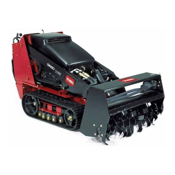
- Page 1 Form No. 3324-220 Rev A Tiller Dingo Attachment Model No. 22445—200000001 & Up Operator’s Manual English (CE)
-
Page 2: Table Of Contents
Before adjusting, cleaning, repairing and inspecting the tiller, lower the tiller and loader arms to the ground and stop the engine. Remove the key. The Toro Company – 1999 8111 Lyndale Ave. South All Rights Reserved Bloomington, MN 55420–1196... -
Page 3: Safety Decals
Safety Decals WARNING POTENTIAL HAZARD There may be buried power, gas, and/or telephone lines in the area needing tilling. WHAT CAN HAPPEN Shock or explosion may occur. # 93–7321 HOW TO AVOID THE HAZARD Have the property or area to be tilled marked for buried lines. -
Page 4: Stability Ratings
Tine width 2.5 in. (6.4 cm) Number of tines Shaft diameter 1.50 in. (3.8 cm) Drive Chain ANSI 60 reduction ratio 1.8:1 Hydraulic motor displacement 6.20 cu. in. (102 cc) Weight 363 lb. (165 kg) Stability Ratings Operation To determine the degree of slope you can traverse with the IMPORTANT: Lift and move the attachment using the tiller installed on a traction unit, find the stability rating traction unit. -
Page 5: Maintenance
Maintenance Service Interval Chart Each Storage Service Operation Hours Hours Service Notes Shaft bearing–lubricate Chain tension–adjust and lubricate initial Tines–check Replace as required Tine bolts–check and tighten Replace as required Chipped surfaces–paint CAUTION POTENTIAL HAZARD If you leave the key in the ignition switch, someone could start the engine. WHAT CAN HAPPEN Accidental starting of the engine could seriously injure you or other bystanders. -
Page 6: Tiller Tine Replacement
Tines should be installed as illustrated in Figure 3 with 2 left hand tines and 2 right hand tines on each hub. m–4414 Figure 3 1. Left hand tine 2. Right hand tine The cutting edges of the tines should face toward the rear of the tiller. -
Page 7: Troubleshooting
Troubleshooting PROBLEM POSSIBLE CAUSES CORRECTIVE ACTION Tiller does not operate. 1. Hydraulic coupler not 1. Check and tighten all couplers. completely connected 2. Defective hydraulic coupler 2. Check couplers and replace any that are defective. 3. An obstruction in a hydraulic 3.