
Related Manuals for Toro 58604


Summary of Contents for Toro 58604
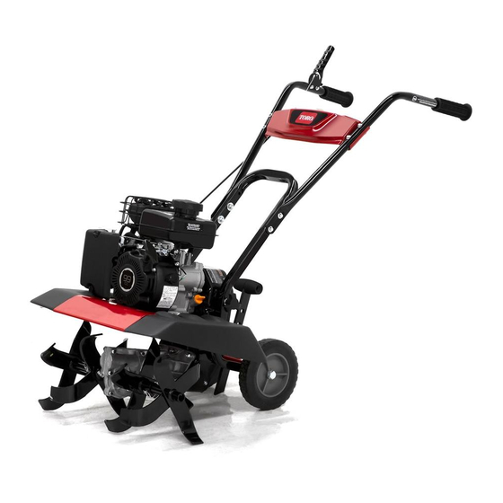
- Page 1 Form No. 3447-108 Rev A Front Tine Tiller/Cultivator Model No. 58604—Serial No. 321000001 and Up *3447-108* Register at www.Toro.com. Original Instructions (EN)
- Page 2 Whenever you need service, genuine Toro parts, or additional information, contact an Authorized Service Dealer or Toro Customer Service and have the model and serial numbers of your product ready. Figure 1 identifies the location of the model and serial numbers on the product.
-
Page 3: Table Of Contents
Contents Safety Safety ............... 3 This machine has been designed in accordance with General Safety ........... 3 ANSI B71.8-2016. Safety and Instructional Decals ......4 Setup ................ 6 DANGER 1 Installing the Tines and Shields ......7 There may be buried utility lines in the work 2 Installing the Handlebars ......... -
Page 4: Safety And Instructional Decals
instruction. Failure to comply with these instructions may result in personal injury or death. Safety and Instructional Decals Safety decals and instructions are easily visible to the operator and are located near any area of potential danger. Replace any decal that is damaged or missing. decal133-8062 133-8062 decal144-4848... - Page 5 decal144-4874 144-4874 1. Warning—read the 3. Installing the Operator’s Manual. shields—slide the side shield on, raise the handlebars, and install the hand knob. 2. Thrown object hazard—keep shields in place when outer tines are installed. decal148-4868 148-4868 1. Warning—read the Operator’s Manual. 6.
-
Page 6: Setup
Setup Loose Parts Use the chart below to verify that all parts have been shipped. Procedure Description Qty. Left outer tine set Right outer tine set Install the tines and shields. Left side shield Right side shield Bolt (M8 x 40 mm) Bolt (M6 x 40 mm) Washer Locknut (M8) -
Page 7: Installing The Tines And Shields
Remove the lock pin from 1 inner tine and verify that the arrows on the tines point in the direction of forward rotation. Note: The arrows rotate counterclockwise Installing the Tines and when viewed from the left side of the machine. Shields Parts needed for this procedure: Left outer tine set... -
Page 8: Installing The Handlebars
Remove the hand knobs from the lower handlebar assembly and rotate the assembly away from the engine. Installing the Handlebars Parts needed for this procedure: Bolt (M8 x 40 mm) Bolt (M6 x 40 mm) Washer Locknut (M8) g358170 Figure 6 Locknut (M6) Left handlebar Middle dash panel... -
Page 9: Installing The Drag Stake
Install the middle dash panel. Route the engine Insert the Z-bend end of the drive cable into the switch cable through the hole on the left side of middle hole of the drive-control lever. the panel as shown in Figure Note: Ensure that there is no excess slack in the cable and that the lever remains in the full... -
Page 10: Connecting The Engine Switch Cable
Connecting the Engine Adding Oil to the Engine Switch Cable Parts needed for this procedure: Engine oil No Parts Required Procedure Procedure Plug the engine switch cable into the engine Move the machine to a level surface. on/off switch. Remove the dipstick. g361563 Figure 13 g360549... -
Page 11: Product Overview
Tilling depth 28 cm (11 inches) g358001 Figure 16 To ensure optimum performance and continued safety certification of the machine, use only genuine Toro 1. Throttle control 9. Removable side shield replacement parts and accessories. Replacement 2. Choke lever 10. Tines parts and accessories made by other manufacturers 3. -
Page 12: Before Operation
Operation • Do not fill the fuel tank indoors. • Do not overfill the fuel tank. Replace the fuel cap and tighten it securely after fueling. Clean up Note: Determine the left and right sides of the spilled fuel before starting the engine. machine from the normal operating position. -
Page 13: Adding Fuel
Adding Fuel Changing the Tine Configuration Fuel Specifications WARNING Type Unleaded gasoline Minimum octane rating 87 (US) or 91 (research When the outer tines are installed, operating octane; outside the US) the machine without the side shields could Ethanol No more than 10% by volume expose you or others to tine contact, causing injury or death. - Page 14 • Narrow tilling—41 cm (16 inch) width For narrow and wide tilling configurations, continue as follows: Install the lock pins. Important: Install the lock pin from the front of the tiller so that the wire hinges over the top of the tine pipe and latches to the pin on the rear of the tine.
-
Page 15: Adjusting The Handlebars
Adjusting the Handlebars Performing Daily Maintenance You can adjust the handlebar height 2 ways. • Remove the fasteners from the left and right Before starting the machine each day, perform the handlebars, align the holes at the desired height, Each Use/Daily procedures listed in Maintenance and secure the handlebars. -
Page 16: Starting The Machine
Operate the engine only in well-ventilated areas. Exhaust gases contain carbon monoxide, which is an odorless, deadly poison. • Use only accessories and attachments approved by The Toro® Company. • Do not change the engine governor settings or overspeed the engine. •... -
Page 17: Adjusting The Drag Stake
Adjusting the Drag Stake After Operation The drag stake helps regulate tilling depth and prevents the tiller from jerking forward during After Operation Safety operation. Set the drag stake in the lowest position to increase resistance to forward motion and to dig deeper;... -
Page 18: Maintenance
• To ensure optimum performance of the machine, Maintenance Safety use only genuine Toro replacement parts and accessories. Replacement parts and accessories • Inspect the machine frequently to ensure that it made by other manufacturers could be dangerous, is in safe working condition and that shear bolts, and such use could void the product warranty. -
Page 19: Pre-Maintenance Procedures
Pre-Maintenance Engine Maintenance Procedures Servicing the Air Cleaner Preparing for Maintenance Service Interval: Every 25 hours Refer to Preparing for Maintenance (page 19). Move the machine to a level surface, shut off the engine, and wait for all moving parts to stop. Remove the air-cleaner cover. -
Page 20: Servicing The Engine Oil
Servicing the Engine Oil Changing the Engine Oil Service Interval: After the first 20 hours/After the first month (whichever comes Engine-Oil Specifications first)—Change the engine oil. Engine oil capacity 0.35 L (11.8 fl oz) Every 25 hours—Change the engine oil when Oil viscosity Refer to the chart below. -
Page 21: Servicing The Spark Plug
Servicing the Spark Plug Checking the Spark Plug Important: Do not clean the spark plug(s). Service Interval: Every 50 hours Always replace the spark plug(s) when it has a Ensure that the air gap between the center and side black coating, worn electrodes, an oily film, or electrodes is correct before installing the spark plug. -
Page 22: Fuel System Maintenance
Fuel System Remove the filter by using a socket to turn it counterclockwise. Maintenance DANGER In certain conditions, fuel is extremely flammable and highly explosive. A fire or explosion from fuel can burn you and others and can damage property. Refer to Fuel Safety (page 12) for a complete... -
Page 23: Belt Maintenance
Belt Maintenance difference should be 0.32 to 0.6 cm (1/8 to 1/4 inch). If the belt needs adjustment, hold the lower jam Checking and Adjusting the nut in place and adjust the upper jam nut in 0.32 cm (1/8 inch) increments. Check the tension Belt Tension again, and repeat as necessary. -
Page 24: Replacing The Drive Belt
Replacing the Drive Belt Installing the Belt Place belt in the transmission pulley groove. Service Interval: Every 50 hours Removing the Belt Remove the pulley cover. g358509 Figure 42 1. Engine pulley 3. Transmission pulley 2. Belt Gently pull the engine recoil rope to rotate the engine pulley while forcing the belt into the g358486 Figure 40... -
Page 25: Cleaning
Cleaning Storage Storage Safety Cleaning the Tine Axle • Shut off the machine and wait for all moving parts Shaft to stop before you leave the operator’s position. Disconnect the spark-plug wire, keep it away from Service Interval: Every 10 hours the plug to prevent accidental starting, and allow the machine to cool before adjusting, fueling, Remove all vegetation, string, wire, and other material... - Page 26 Start the engine and run it until it shuts off. Dispose of fuel properly. Recycle the fuel according to local codes. Important: Do not store fuel containing stabilizer/conditioner longer than the duration recommended by the fuel-stabilizer manufacturer. Remove and check the condition of the spark plug;...
-
Page 27: Troubleshooting
Troubleshooting Problem Possible Cause Corrective Action The engine does not start. 1. The fuel tank is empty. 1. Add fuel. 2. The spark-plug wire is loose or 2. Install the wire on the spark plug. disconnected. 3. The engine switch is in the O 3. - Page 28 While the exposure from Toro products may be negligible or well within the “no significant risk” range, out of an abundance of caution, Toro has elected to provide the Prop 65 warnings. Moreover, if Toro does not provide these warnings, it could be sued by the State of California or by private parties seeking to enforce Prop 65 and subject to substantial penalties.