Motorola SRX 2200 User Manual
Hide thumbs
Also See for SRX 2200:
- Quick reference manual (48 pages) ,
- Quick reference card (2 pages) ,
- Service manual (438 pages)
Table of Contents
Advertisement
Quick Links
Advertisement
Table of Contents

Related Manuals for Motorola SRX 2200


Summary of Contents for Motorola SRX 2200
-
Page 3: Table Of Contents
Contents Documentation Copyrights...13 Declaration of Conformity......6 Disclaimer........14 Important Safety Information..8 Getting Started....... 15 How to Use This Guide........15 Notations Used in This Manual......15 Software Version......9 Additional Performance Enhancement..15 Notice to Users (FCC and Industry ASTRO 25 Enhanced Data....15 Canada)............9 Dynamic System Resilience (DSR).. - Page 4 Attaching the Antenna........19 Selecting a Zone..........40 Removing and Attaching the Accessory Selecting a Radio Channel......40 Connector Cover........20 Receiving and Responding to a Radio Call... 40 Attaching the Belt Clip........21 Receiving and Responding to a Turning On the Radio........22 Talkgroup Call........40 Adjusting the Volume........23 Receiving and Responding to a...
- Page 5 Viewing a Scan List......47 Triggering Emergency......55 Viewing and Changing the Priority Radio Alerts When Man Down Status..........47 Enhanced is Triggered....56 Scan.............. 47 Exiting Man Down Feature....57 Turning Scan On or Off.......47 Re-Initiating Man Down.......57 Making a Dynamic Priority Change Testing the Man Down Feature...57 (Conventional Scan Only)....
- Page 6 Pairing with Low Frequency- Using the Flip Display......77 Motorola Proximity Pairing (LF- Selecting a Basic Zone Bank....77 MPP) Feature........ 69 Selecting the Power Level....77 Radio Indications of Lost Bluetooth Controlling the Display Backlight..78 Connection........70 Setting Up the Radio Display and Standard Pairing Feature....71...
- Page 7 Special Channel Assignments....... 94 Emergency Channel......94 Non-Commercial Call Channel... 94 Operating Frequency Requirements....94 Declaration of Compliance for the Use of Distress and Safety Frequencies....97 Technical Parameters for Interfacing External Data Sources......97 Glossary..........98 Limited Warranty......103 MOTOROLA COMMUNICATION PRODUCTS........... 103 English...
-
Page 8: Declaration Of Conformity
Name: Motorola Solutions, Inc. Address: 1303 East Algonquin Road, Schaumburg, IL 60196-1078, U.S.A. Phone Number: 1-800-927-2744 Hereby declares that the product: Model Name: SRX 2200 conforms to the following regulations: FCC Part 15, subpart B, section 15.107(a), 15.107(d) and section 15.109(a) English... - Page 9 Class B Digital Device As a personal computer peripheral, this device complies with Part 15 of the FCC Rules. Operation is subject to the following two conditions: 1 This device may not cause harmful interference, and 2 This device must accept any interference received, including interference that may cause undesired operation. Note: This equipment has been tested and found to comply with the limits for a Class B digital device, pursuant to part 15 of the FCC Rules.
-
Page 10: Important Safety Information
Radios which contains important operating instructions for safe usage and RF energy awareness and control for Compliance with applicable standards and Regulations. For a list of Motorola-approved antennas, batteries, and other accessories, visit the following website: http://www.motorolasolutions.com/APX Under Industry Canada regulations, this radio... -
Page 11: Software Version
• This device must accept any interference received, including interference that may cause undesired operation. • Changes or modifications made to this device, not expressly approved by Motorola, could void the authority of the user to operate this equipment. English... -
Page 12: Consignes De Sécurité Importantes
Cet émetteur radio a été approuvé par Industrie Canada pour utilisation avec une antenne approuvée Cette radio ne doit être utilisée qu'à des fins par Motorola offrant le gain maximal autorisé et professionnelles. Avant d'utiliser la radio, lisez le l'impédance requise pour le type d'antenne indiqué. Il... -
Page 13: Version Logicielle
Motorola, peuvent annuler le droit de l'utilisateur à Version logicielle utiliser cet équipement. Toutes les fonctions décrites dans les sections suivantes sont prises en charge par la version R14.50.00 ou les versions ultérieures du logiciel de la radio. Pour obtenir davantage de renseignements à propos des fonctions prises en charge, adressez-vous à... -
Page 14: Computer Software Copyrights
Motorola. Furthermore, the purchase of Motorola products shall not be deemed to grant either directly or by implication, estoppel, or otherwise, any license under the copyrights, patents or patent... -
Page 15: Documentation Copyrights
No duplication or distribution of this document or any portion thereof shall take place without the express written permission of Motorola. No part of this manual may be reproduced, distributed, or transmitted in any form or by any means, electronic or mechanical, for any purpose without the express written permission of Motorola. -
Page 16: Disclaimer
However, no responsibility is assumed for inaccuracies. Furthermore, Motorola reserves the right to make changes to any products herein to improve readability, function, or design. Motorola does not assume any liability arising out of the applications or use of any product or circuit described herein;... -
Page 17: Getting Started
damage to the equipment if not carefully Getting Started observed. Note: How to Use This Guide An operational procedure, practice, or condition and so on, which is essential to This User Guide covers the basic operation of the emphasize. APX Portables. However, your dealer or system administrator may Additional Performance Enhancement have customized your radio for your specific needs. -
Page 18: Crosstalk Prevention
A maximum of four talkgroups SecureNet allows user to perform secured can be supported when Vote Scan channels are communications on an Analog or Motorola Data being used. Communication (MDC) channel. The MDC Over-the- Smart PTT is supported with this enhancement as... -
Page 19: What Your Dealer/System Administrator Can Tell You
Note: User Selectable Talkgroups are not compatible with this Conventional Talkgroup Enhancement. What Your Dealer/System Administrator Can Tell You Check with your dealer or system administrator for the correct radio settings, if the radio is to be operated in extreme temperatures (less than -30 °C or more than +60 °C). -
Page 20: Preparing Your Radio For Use
Accessories on page Note: When charging a battery attached to a radio, turn the radio off to ensure a full charge. To charge the battery, place the battery (with or without the radio) in a Motorola-approved charger. English... -
Page 21: Attaching The Antenna
2 To remove the battery, squeeze the release latches at the bottom of the battery until the Attaching the Antenna battery releases from the radio and remove the battery from the radio. Ensure the radio is turned off before attaching the antenna. -
Page 22: Removing And Attaching The Accessory Connector Cover
2 Turn the antenna clockwise to attach to the radio. Removing and Attaching the Accessory Connector Cover The accessory connector is on the antenna side of the radio. It is used to connect accessories to the radio. Note: To prevent damage to the connector, shield it with the connector cover when not in use. -
Page 23: Attaching The Belt Clip
6 Once in place, tighten by rotating the thumbscrew clockwise by hand. Attaching the Belt Clip 1 Align the grooves of the belt clip with those of the radio and press upward until you hear a click to attach the belt clip. 2 Rotate and lift the connector cover to disengage it from the radio. -
Page 24: Turning On The Radio
downward and away from the radio to remove the clip. • If the power-up test is successful, you see momentary on the radio display, followed by the Home screen. • If the power-up test is successful, you see a splash screen on the radio display, followed by the Home screen. -
Page 25: Adjusting The Volume
2 To turn off the radio, rotate the On/Off/Volume Control Knob counterclockwise until you hear a click. 2 To decrease the volume, rotate this knob Adjusting the Volume counterclockwise. Ensure the radio is power on and the main speaker is pointed towards you for increased loudness and intelligibility, especially in areas with loud background noises. -
Page 26: Identifying Radio Controls
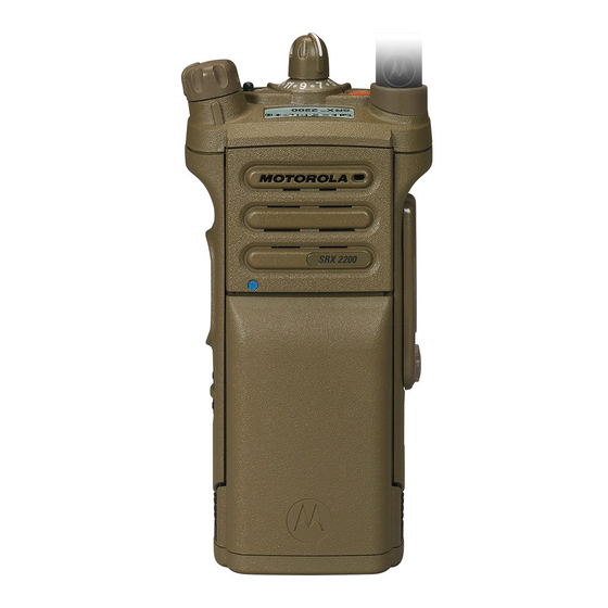
Identifying Radio Controls Radio Parts and Controls Antenna Top (Orange) Button Microphone Accessory Connector cover English... -
Page 27: Programmable Features
Battery Latch Programmable Features 2–Position Concentric Switch Any reference in this manual to controls that are preprogrammed means that a qualified radio 3–Position A/B/C Switch technician must use the radio programming software 16–Position Select Knob to assign a feature to a control. On/Off/Volume Control Knob Your dealer can program the programmable buttons as shortcuts to radio functions or preset channels/... - Page 28 Remote Speaker Microphone cancels an emergency alarm or and Bluetooth headset. call. Bluetooth Keys up the Bluetooth Headset Internet Protocol Display the Internet Protocol Headset PTT microphone. Address (IP) address, device name and status of the radio. Bluetooth Clear Allows you to clear all pairing information for Bluetooth.
- Page 29 separately programmed buttons Secure Toggles the Secure for four different features. Transmission On or Off when Transmission Select the Secure/Clear Strapping Private Line Overrides any coded squelch fields is set to Select for the (Conventional Defeat (DPL or PL) that is and Trunking) current channel and when the (Conventional...
-
Page 30: Assignable Settings Or Utility Functions
banks (A, B ... X or Y) of 3 Accessing the Preprogrammed Functions zones. You can access various radio functions through a Assignable Settings or Utility Functions short or long press of the relevant programmable buttons. Locks or unlocks the Controls Lock programmable buttons, Push-To-Talk (PTT) Button... - Page 31 Press and hold down PTT button to talk. Release the PTT button to listen. The microphone is activated when the PTT button is pressed. • While a call is not in progress, the PTT button is used to make a new call. See Methods to Make a Radio Call on page 42 for more information.
-
Page 32: Identifying Status Indicators
Received Signal Strength Indicator Identifying Status Indicators (RSSI) Status Icons The number of bars displayed repre- sents the received signal strength for the Selected icons are also shown on the first row of the current site, for trunking only. The more 112 x 32 pixel top monochrome display screen of stripes in the icon, the stronger the sig- your radio. - Page 33 Power Level Basic Zone Bank 1 L – Radio is set at Low power. A – Radio is in Zone 1. H – Radio is set at High power. B – Radio is in Zone 2. C – Radio is in Zone 3. Scan Radio is scanning a scan list.
-
Page 34: Led Indicator
Bluetooth is currently connected to the Y – Contains Zone 73, Zone 74 and Zone 75. external Bluetooth device. ® Secure Operation The radio Wi-Fi network is connected. The number of bars displayed repre- On – Secure operation. sents the signal strength of the Wi-Fi signal. - Page 35 Double blinking red Radio is in Emergency Mode. Solid green and Radio is reading or upgrading by CPS. short blinking blue Rapidly blinking Radio has failed the self test with long interval upon powering up or encountered a fatal error. Blinking blue three Bluetooth is powering on or times...
-
Page 36: Intelligent Lighting Indicators
Note: qualified technician to be permanently No LED indication when the radio receives a disabled. Consult your dealer for further clear (non-secured) transmission in trunking details if you want to disable it. Mode. LED indication can be preprogramed by Intelligent Lighting Indicators This feature temporarily changes the backlight of the top display screen, and adds a color bar to the main display screen to help signal that a radio event has occurred. -
Page 37: Alert Tones
Backlight and Bar Notification When Color Green Call Alerts The radio receives a private call. The radio receives a phone call. The radio receives a call alert. The radio receives a selective call. The radio enters Geofence. Alert Tones Your radio uses alert tones to inform you of the condition of your radio. The following table lists these tones and when they occur. - Page 38 You Hear Tone Name Heard Man Down Entry When radio initiates Man Down mode. After time out. Long, Low- Time-Out Timer Timed Out Pitched Tone Talk Prohibit/PTT Inhibit (When PTT button is pressed) transmissions are not allowed. Lack of Voice PTT Time out When the radio ends your call after it detected there are lack of voice for 5 seconds after the PTT is pressed and hold.
- Page 39 You Hear Tone Name Heard Emergency Alarm /Call En- When entering the emergency state. Central Echo When central controller has received a request from a radio. Long, Medium- Volume Set When volume is changed on a quiet channel. Pitched Tone When exiting the emergency state.
- Page 40 You Hear Tone Name Heard Gurgle Dynamic Regrouping (When PTT button is pressed) a dynamic ID has been received. Talk Permit (When PTT button is pressed) is verifying with the system for ac- cepting its transmissions. Unique, Low- New Message When a new message is received.
- Page 41 You Hear Tone Name Heard Unique High- Enhanced Zone Bank Down When EZB Down button is pressed to scroll the Enhance Zone Low Tone Bank down. English...
-
Page 42: General Radio Operation
a) Rotate the preprogrammed 16–Position General Radio Operation Select Knob to the desired channel. b) Press the PTT button to transmit on the Selecting a Zone displayed zone channel. Your radio must be preprogrammed to allow you to Receiving and Responding to a Radio Call use this feature. -
Page 43: Receiving And Responding To A Private Call (Trunking Only)
• For ASTRO Conventional system, the LED lights Note: up solid yellow. The display shows the talkgroup With the inactivity timer enabled (optional), alias or ID, and the caller alias or ID. when there is no response from the receiving radio, the calling radio exits the call with Menu •... -
Page 44: Methods To Make A Radio Call
Note: • The 16-Position Select Channel Knob. With the inactivity timer enabled (optional), if Making a Talkgroup Call there is no response to the call after the timer expires, your radio exits the call with Menu To make a call to a group of users, your radio must Inactive Exit tone. -
Page 45: Switching Between Repeater Or Direct Operation Button
channel is an indication that the radio is not working Switching Between Repeater or Direct properly. This is not the case. Operation Button Digital technology quiets the transmission by The Repeater Operation increases the radio removing the noise from the signal and allows only coverage area by connecting with other radios the clear voice or data information to be heard. -
Page 46: Monitoring Conventional Mode
Monitoring Conventional Mode Your radio may be preprogrammed to receive Private- ® Line (PL) calls. 1 Momentarily press the Monitor button to listen for activity. The Carrier Squelch indicator appears on the display. 2 Press and hold the Monitor button to set continuous monitor operation. -
Page 47: Advanced Features
Responding to the Dynamic Regrouping Feature Advanced Features (Trunking Only) This feature allows the dispatcher to temporarily Advanced Call Features reassign selected radios to a particular channel where they can communicate with each other. This feature is Selective Call (ASTRO Conventional Only) typically used during special operations and is This feature allows you to receive a call from a enabled by a qualified radio technician. -
Page 48: Scan Lists
that you were using before the radio was dynamically channel, once the user has selected regrouped. the dynamic-regrouping position. Requesting a Reprogram (Trunking Only) Select Select-disabled radios cannot change This feature allows you to notify the dispatcher when Disabled channels while dynamically regrouped. you want a new dynamic regrouping assignment. -
Page 49: Viewing A Scan List
in your radio. These lists must be preprogrammed by One channel, regardless of traffic on non- a qualified radio technician. priority channels. • No icon indicates that the current channel is Viewing a Scan List deleted from the scan list. Turn the 16-Position Select Knob to view the members on the list. -
Page 50: Deleting A Nuisance Channel
This change remains in effect until scan is turned off. When the radio is locked onto the channel to be Scan then reverts to the preprogrammed (original) deleted, press the preprogrammed Nuisance setting. Delete button. Making a Dynamic Priority Change via the The radio continues scanning the remaining channels preprogrammed Dynamic Priority button: in the list. -
Page 51: Receiving A Call Alert Page
Note: • Silent Emergency Alarm This feature must be preprogrammed by a Check with your dealer or system administrator for qualified radio technician. more information on the programming of this feature. Receiving a Call Alert Page Only one of the Emergency modes above can be When you receive a Call Alert page, you hear four assigned to the preprogrammed Emergency button. -
Page 52: Sending An Emergency Alarm
The display shows EMERGENCY and the current • send alarm and/or make zone or channel. You hear a short medium- emergency call. pitched tone and the LED blinks red Non-Tactical/ The radio reverts to the momentarily. Revert for preprogrammed • The radio sounds a short low-pitched tone to Trunking emergency talkgroup to... -
Page 53: Sending An Emergency Alarm With Emergency Call
If successful, the display shows EMERGNCY on the pitched tone and the LED blinks red momentarily. current zone and channel. You hear a short, medium-pitched tone and the LED blinks red • You hear the radio sounds a short low-pitched momentarily. -
Page 54: Sending A Silent Emergency Alarm
• Press and release the PTT button to exit the 4 Release the PTT button to end the transmission Silent Emergency Alarm mode and enter and wait for a response from the dispatcher. regular dispatch or Emergency Call mode. 5 To exit Emergency Call, press and hold the Change of Channels during Emergency preprogrammed Emergency button for about a second. -
Page 55: Emergency Find Me
Sending an Emergency Alarm on page Press the pre-programmed Emergency button to Sending an Emergency Call (Trunking transmit the EFM beacon. Only) on page 50, Sending an Emergency Alarm with Emergency Call on page 51, or The receiving radio displays BEAC RX . Sending a Silent Emergency Alarm on page Man Down... - Page 56 radio must stay in this condition for a preprogrammed 3 Man Down condition continues for the time amount of time before the Emergency Alarm or Call is duration defined in the Post-Alert Timer field. Once activated. the timer expires, the Emergency alarm is transmitted.
-
Page 57: Pre-Alert Timer
If the radio is preprogrammed to horizontal Timer is initiated, the radio alerts the user with an only, it must be worn in a vertical position audible tone and displays the “MAN-DOWN” text. otherwise the Man Down alert may be Exiting Man Down Feature on page 57 to exit inadvertently triggered. -
Page 58: Radio Alerts When Man Down Enhanced Is Triggered
coordinates to dispatcher if these features are the current radio speaker level. This acts as a beacon enabled. User can exit Emergency following the to find the radio. Emergency procedure. See Emergency Operation Note: page 49 for details. If the radio is programmed with Silent Note: Emergency, the radio inhibits the alert tone At this point the Man Down features is... -
Page 59: Exiting Man Down Feature
• The alert tone continues when you change to a Testing the Man Down Feature channel with Emergency and similar Man Down Enable the Emergency feature with Silent Alarm configuration. disabled, but not in Surveillance Mode before running Exiting Man Down Feature this test on the radio. -
Page 60: Secure Operations
The Secure/Clear switch only applies Unlike other forms of security, Motorola digital when the radio is transmitting. encryption provides signaling that makes it virtually impossible for others to decode any part of an Selecting Clear Transmissions encrypted message. -
Page 61: Managing Encryption
If the “Ignore Secure/Clear Switch when When the key has been loaded successfully, one of Strapped” programming option is enabled, the following scenarios occurs: the radio transmits without displaying any • You hear the radio sounds a short tone for single- messages in the strapped mode of key radios. - Page 62 Note: Trunked If the radio is used for both Do not press the Top (Orange) button conventional and trunked Multikey before pressing the Top Side (Select) applications, strap the encryption button, unless you are in an emergency keys for trunking on a per-talkgroup situation as this sends an emergency or announcement-group basis.
- Page 63 Note: when all of the encryption keys is erased. Without this The rekey operation failure indicates that UKEK key, the radio cannot be rekeyed over the air. your radio does not contain the Unique Note: Shadow Key (USK). This feature must be preprogrammed by a qualified radio technician.
-
Page 64: Global Positioning System / Global Navigation Satellite System
geographical location of your radio. The geographical signal at location is expressed as latitude and longitude or transmitting radio. Military Grid Reference System (MGRS) format per request from customers. Expander Expands the speech while the noise flow Note: remains the same at This feature is addressed as GPS across the receiving radio. -
Page 65: Gps Performance Enhancement
Therefore, maximizing your view of unobstructed sky Note: is essential for optimum performance. Even where adequate signals from multiple satellites are available, your GPS feature only Where adequate signals from multiple satellites are provides an approximate location, usually not available (usually because you cannot establish a within 10 meters from your actual location, but view of a wide area of the sky), the GPS feature of sometimes farther away. -
Page 66: Peer-Location On The Display (Astro Conventional Only)
Peer-Location on the Display (ASTRO Conventional short coordinates. There are two different formats only) available. Refer to the following list for the details shown in the Peer-Location quick text. Consult your This feature is only available for radio-to-radio voice agent to pick the best format to configure to your transmissions, dispatch call and selective call in radio. -
Page 67: Trunking System Controls
The PTT ID seen here is optional to be shown 2 Press the PTT button to talk, and release the on the display per requirement of usage. button to listen. Trunking System Controls Out-of-Range Radio When your radio goes out of the range of the system, Operating in Failsoft System it can no longer lock onto a control channel. -
Page 68: Site Display And Search Button
Home screen. Note: Site Display and Search Button It is recommended to use Motorola proprietary The Site Display and Site Search button allows you Mission Critical Wireless (MCW) devices with to view the name of the current site or force your APX radios during Mission Critical operations radio to change to a new one. -
Page 69: Turning On Bluetooth
If Bluetooth fails to launch, the display shows devices to re-establish a new set of BT ON FL. pairing keys. See Pairing with Low Frequency-Motorola Proximity Pairing Turning Off the Bluetooth (LF-MPP) Feature on page 69 and Standard Pairing Feature on page 71. -
Page 70: Bluetooth Drop Timer
again, they can resume the Bluetooth Re-Pair Tim- Re-Pair Timer Scenarios connection without user intervention. er Options tablish the Bluetooth Connection Re-Pair Tim- Re-Pair Timer Scenarios for a period of time depending er Options upon the Drop Timer value. If the Immediate •... -
Page 71: Pairing With Low Frequency
0 – 15 minutes, 2 To establish the Bluetooth Connection, see Pairing hours, 4 hours or 8 hours. with Low Frequency-Motorola Proximity Pairing (LF- MPP) Feature on page 69 or Standard Pairing Do note there are exceptions for Feature on page 71 . -
Page 72: Radio Indications Of Lost Bluetooth Connection
The display shows PAIRFAIL. sight include trees, buildings, mountains, cars and etc. Repeat this step. For high degree of reliability, Motorola recommends The radio tries to establish connection with the device to NOT separate the radio and the accessory. once paired. -
Page 73: Standard Pairing Feature
It is set to turn off by default. preprogrammed buttons must be preprogrammed by a qualified radio The radio only search for HSP devices and Motorola technician. Check with your dealer or system MCW & OCW accessories. Radio filters out other administrator for more information. - Page 74 If successful, the display shows SRCH ON device is unpaired. The display shows <Device • followed by SRCH END when the radio is pairing Type> UNPAIRED. with a device found. The display shows Turning On Bluetooth Visibility <Device Name> PAIRED to indicate pairing is complete.
-
Page 75: Turning On The Bluetooth Audio (Routing The Audio From The Radio To The Headset)
Receiving Pairing Request from other Devices You hear a short, medium-pitched tone. The display shows SPKR ON. Turn on your radio Bluetooth Visible mode. Adjusting the Volume of the Radio from Bluetooth Your radio automatically accept the request and Audio Device pair with any request received from other device. -
Page 76: Over-The-Air Programming (Pop 25, Astro 25, Astro Conventional)
You hear a short, medium-pitched tone. The Once a configuration upgrade is downloaded to your display shows PLS WAIT to indicate clearing is radio, you can install new changes immediately or delay changes to be installed on the radio when it is in progress. -
Page 77: Site Selectable Alerts (Astro 25)
Note: Note: This feature must be preprogrammed by a Pressing this preprogrammed playback qualified radio technician. button enables the voice feature to announce in High priority. Check with your agent if Voice Announcement is available for the feature you need. All the three programmable buttons at the side of the radio support this feature. -
Page 78: Wi-Fi
Upon the activation of a SSA, the receiving radios Note: display the alert alias and generate the periodic alert Wi-Fi Network Name (SSID) for the radio to tone. connect to must be preprogrammed by a qualified radio technician. Check with your Note: dealer or system administrator for more Alert alias, alert tone, and alert period can be... -
Page 79: Utilities
Selecting a Basic Zone Bank WF SRCHG Looking for available Wi-Fi networks that have been The Basic Zone Select feature must to be preprogrammed into the radio. preprogrammed to the 3-position A-B-C switch, while the Basic Zone Bank feature must be WF CNTG In the process of connecting to a preprogrammed to any side button or Top (Orange) -
Page 80: Controlling The Display Backlight
This feature enables you to reduce the transmit power Note: level for specific case that requires a lower power The backlight remains on for a level. You can select the power level at which your preprogrammed time before it automatically radio transmits. -
Page 81: Locking And Unlocking The Controls
low illumination backlight to allow the user to operate Locking and Unlocking the Controls the radio with the goggles on. You can lock the programmable buttons, switches, Caution: and rotary knobs of your radio to avoid inadvertent Remove your NVG if you operate the radio in entry. -
Page 82: Using The Time-Out Timer
Using the Time-Out Timer The time-out timer restarts and the LED lights up solid red. This feature turns off the transmitter of your radio. You cannot transmit longer than the preset timer Using Conventional Squelch Operation Features setting. This feature filters out unwanted calls with low signal If you attempt to do so, the radio automatically stops strength or channels that have a higher than normal your transmission, and you hear a talk-prohibit tone. -
Page 83: Using The Pl Defeat Feature
Note: Option Result When this feature is active, the Carrier Digital Carrier-Operated You hear any digital traf- Squelch status indicator is displayed. Squelch (COS) fic. Digital PTT ID Support Normal Squelch You hear any digital traf- This feature allows you to see the radio ID (number) fic having the correct net- of the radio from whom you are currently receiving a work access code. -
Page 84: Transmit Inhibit
inhibited. The LED lights up solid yellow to indicate Mode Description that the channel is busy. presses within the preprogram- The following table shows the variations of smart med time limit. PTT: Transmit Inhibit Mode Description This feature is available for APCO 25 trunking, Type II Transmit Inhibit You cannot transmit if any traffic trunking and Conventional operations for all APX... - Page 85 Note: Note: Acknowledgement of any messages required If the user has disabled TX Inhibit via the from the radio is not transmitted if the Transmit softkey and then moves the switch to the Inhibition is enabled. position where TX Inhibit is enabled, the new value overwrites the menu value.
-
Page 86: Helpful Tips
Motorola into the radio and the radio’s submergibility details the disassembly, test, and will be lost. -
Page 87: Cleaning Your Radio
Otherwise, the water will decrease the connectors, controls or crevices. Dry the radio audio quality of the radio. thoroughly with a soft, lint-free cloth. • Do not disassemble the radio. This could 3 Clean battery contacts with a lint-free cloth to damage radio seals and result in leak remove dirt or grease. - Page 88 Washing The Radio 1 Submerge the radio (with battery attached) completely into the tap water while shaking it for approximately 20 seconds. 3 Dip the radio completely into the detergent solution and repeat turning action for both knobs, 3-Position A/B/C and the Secure Switch. 2 Remove the radio from the water and perform the following.
- Page 89 4 Lightly scrub the plastic area (front, back, bottom, top and side planes) of the radio with the small brush.Take extra care around the Speaker Grill and Microphone port openings. 6 Submerge the radio into tap water and shake it to remove the detergent.
- Page 90 Washing the Battery 1 Rinse the battery under running water to remove any excess debris. 8 Shake off excess water and pat dry the radio with a dry towel. Take extra care to tap/shake out any trapped water from the speaker grill area. 2 Using the small brush dipped in the detergent solution, lightly scrub the front, botom and sides of the battery.
- Page 91 5 Rinse the battery under running water to remove 2 Use your thumb or finger to lightly rub clean the any excess detergent. rubber seal. Washing the Universal Connector Cover 1 Dip the universal connector cover into tap water followed by the detergent solution. English...
-
Page 92: Proper Ways To Handle The Radio
For a contract service agreement, • Avoid subjecting the radio to an excess of liquids. please contact your nearest Motorola service or sales Do not submerge the radio unless it is ruggedized. representative, or an authorized Motorola dealer. -
Page 93: Battery Care
In this case, replace the battery with a fully charged one. Battery Recycling and Disposal In the U.S. and Canada, Motorola participates in the nationwide Rechargeable Battery Recycling Corporation (RBRC) program for battery collection ™... - Page 94 and recycling. Many retailers and dealers participate in this program. For the location of the drop-off facility closest to you, access RBRC's Internet web site at www.rbrc.com call 1-800-8-BATTERY. This internet site and telephone number also provide other useful information concerning recycling options for consumers, businesses, and governmental agencies.
-
Page 95: Accessories
Accessories The accessory link below is for APX radios. Not all accessories are FCC certified to operate with all APX models and/or bandsplits. Please refer to the specific APX radio price pages for a list of FCC certified accessories or contact your sales representative for accessory compatibility. -
Page 96: Maritime Radio Use In The Vhf Frequency Range
• distance to a well-known landmark Maritime Radio Use in the VHF • vessel course, speed or destination Frequency Range 5 State the nature of the distress. 6 Specify what kind of assistance you need. Special Channel Assignments 7 State the number of persons on board and the number needing medical attention, if any. - Page 97 • on ships subject to Part II of Title III of the 156.050 160.650 Communications Act, the radio must be capable of 156.100 160.700 operating on the 156.800 MHz frequency. • on ships subject to the Safety Convention, the 156.150 160.750 radio must be capable of operating: 156.200...
- Page 98 156.900 161.500 156.325 160.925 156.950 161.550 67** 156.375 156.375 157.000 161.600 156.425 156.425 157.050 161.650 156.475 156.475 157.100 161.700 156.575 156.575 157.150 161.750 156.625 – 157.200 161.800 156.675 156.675 157.250 161.850 156.725 156.725 157.300 161.900 157.350 161.950 157.400 162.000 77** 156.875 –...
-
Page 99: Declaration Of Compliance For The Use Of Distress And Safety Frequencies
maritime use when it operates on the distress and 157.225 161.825 safety frequencies specified in RSS-182 Section 7.3. 157.275 161.875 Technical Parameters for Interfacing External 157.325 161.925 Data Sources 157.375 161.975 RS232 SB9600 157.425 162.025 Input Volt- 3.6V Note: age (Volts Peak-to- * Simplex channels 3, 21, 23, 61, 64, 81, 82, peak) -
Page 100: Glossary
Feature that responds to the Automatic Registration Service presence of an RF carrier by opening or unmuting (turning ASTRO 25 Motorola standard for wireless on) a receiver’s audio circuit. A digital trunked communications. squelch circuit silences the ASTRO Motorola standard for wireless... - Page 101 operations of the trunked Digital Signal An RF signal that has a pulsed, repeaters. or discrete, nature, rather than a continuous nature. Channel A group of characteristics such as transmit/ receive frequency Dispatcher An individual who has radio pairs, radio parameters, and system management duties.
- Page 102 Home screen The first display information Motorola Data Communication after the radio completes its Monitor Check channel activity by self test. pressing the Monitor button. If IV&D Integrated Voice and Data the channel is clear, you hear static. If the channel is in use, Key-variable loader: A device you hear conversation.
- Page 103 is sent out on this same Push-To-Talk. The PTT button channel. engages the transmitter and puts the radio in transmit Operation Critical Wireless (send) operation when OTAR Over-the-air rekeying. pressed. Page A one-way alert, with audio The part of the general Radio Frequency and/or display messages.
- Page 104 unwanted signals before they Trunking The automatic sharing of are heard in the speaker. communications paths between a large number of users (see Standby An operating condition whereby Conventional). the radio’s speaker is muted but still continues to receive Trunking Priority A scan list that includes data.
-
Page 105: Limited Warranty
MOTOROLA, at its option, will at no charge either Limited Warranty repair the Product (with new or reconditioned parts), replace it (with a new or reconditioned Product), or MOTOROLA COMMUNICATION PRODUCTS refund the purchase price of the Product during the warranty period provided it is returned in accordance with the terms of this warranty. -
Page 106: Ii. General Provisions
MOTOROLA offers the following optional extended and conditions. Repairs will be made only at the service contracts. designated MOTOROLA repair depot. Local services are not included. MOTOROLA will pay for outbound SERVICE FROM THE START (SfS) shipping via MOTOROLA'S normal shipping methods. COMPREHENSIVE Provides for extended hardware repair coverage II. -
Page 107: Iii. State Law Rights
Product (e.g., dealer or communication INABILITY TO USE SUCH PRODUCT, TO THE service provider), it can facilitate your obtaining FULL EXTENT SUCH MAY BE DISCLAIMED BY warranty service. You can also call MOTOROLA at LAW. 1-800-927-2744 US/Canada. III. STATE LAW RIGHTS: V. -
Page 108: Vi. Patent And Software Provisions
VI. PATENT AND SOFTWARE PROVISIONS: interfere with MOTOROLA's normal warranty inspection and testing of the Product to verify any MOTOROLA will defend, at its own expense, any suit warranty claim. brought against the end user purchaser to the extent 6 Product which has had the serial number removed that it is based on a claim that the Product or parts or made illegible. -
Page 109: Vii. Governing Law
MOTOROLA. granted by implication, estoppel or otherwise under MOTOROLA patent rights or copyrights. MOTOROLA will have no liability with respect to any claim of patent infringement which is based upon the VII. GOVERNING LAW: combination of the Product or parts furnished... - Page 110 Australian Consumer Law. If you have any queries, please call Motorola Solutions Australia at 1800 457 439. You may also visit our website: http://www.motorolasolutions.com/XA-EN/Pages/ Contact_Us for the most updated warranty terms. English...
- Page 112 MOTOROLA, MOTO, MOTOROLA SOLUTIONS and the Stylized M logo are trademarks or registered trademarks of Motorola Trademark Holdings, LLC and are used under license. All other trademarks are the property of their respective owners. © 2011–2016 Motorola Solutions, Inc. All rights reserved.