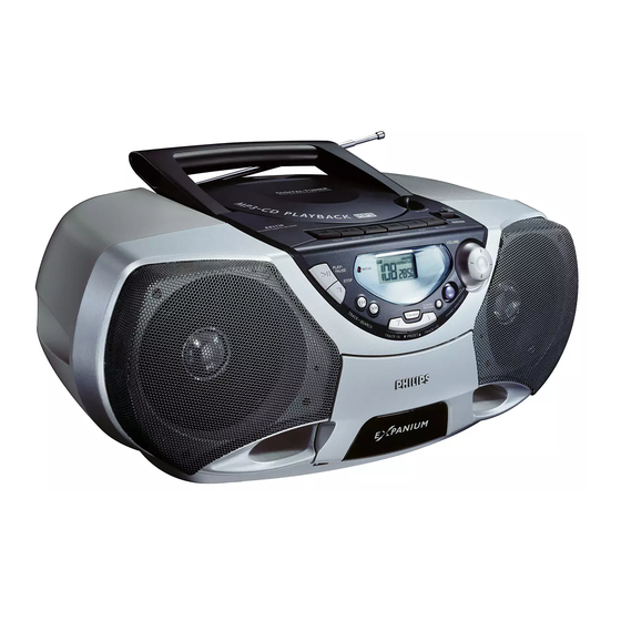
Philips AZ1138 Service Manual
Mp3-cd soundmachine
Hide thumbs
Also See for AZ1138:
- User manual (16 pages) ,
- User manual (46 pages) ,
- Specifications (2 pages)
Table of Contents
Advertisement
Quick Links
Download this manual
See also:
User Manual
MP3-CD Soundmachine
TABLE OF CONTENTS
Handling Chip Components and Safety ..........................1 - 1
Technical Specification & Measurement Setup ...............2 - 1
Service Measurement......................................................2 - 2
Connections and controls ................................................3 - 1
Instructions for Use .............................................3 - 2 .. 3 - 6
Disassembly Diagram......................................................4 - 1
CD Service Test program .....................................4 - 2 .. 4 - 3
Block Diagram .................................................................5 - 1
Wiring Diagram ................................................................5 - 2
circuit diagram .........................................................6 - 1
layout diagram.........................................................6 - 2
circuit diagram .........................................................7 - 1
layout diagram.........................................................7 - 2
©
Copyright 2001 Philips Consumer Electronics B.V. Eindhoven, The Netherlands
All rights reserved. No part of this publication may be reproduced, stored in a retrieval
system or transmitted, in any form or by any means, electronic, mechanical, photocopying,
or otherwise without the prior permission of Philips.
Published by YT 0137 Service Audio
Printed in The Netherlands
Subject to modification
circuit diagram .........................................................8 - 1
layout diagram.........................................................8 - 2
circuit diagram (CD part) .........................................9 - 1
layout diagram (copper side)...................................9 - 2
circuit diagram (power & rectifier part) ....................9 - 3
layout diagram (component side) ............................9 - 4
circuit diagram .......................................................10 - 1
layout diagram.......................................................10 - 2
Exploded view - tape deck ............................................11 - 1
Exploded view - cabinet ................................................11 - 2
Mechanical partslist...............................................11 - 1
Electrical partslist ...........................................12 - 1 .. 12 - 11
AZ1138
all versions
CLASS 1
LASER PRODUCT
© 3140 785 22800
Advertisement
Table of Contents

Related Manuals for Philips AZ1138


Summary of Contents for Philips AZ1138
-
Page 1: Table Of Contents
LASER PRODUCT © Copyright 2001 Philips Consumer Electronics B.V. Eindhoven, The Netherlands All rights reserved. No part of this publication may be reproduced, stored in a retrieval system or transmitted, in any form or by any means, electronic, mechanical, photocopying, or otherwise without the prior permission of Philips. - Page 2 1 - 1 HANDLING CHIP COMPONENTS © ñ WARNING WAARSCHUWING All ICs and many other semiconductors are susceptible to Alle IC´s en vele andere halfgeleiders zijn gevoelig voor electrostatic discharges (ESD). Careless handling during electrostatische ontladingen (ESD). repair can reduce life drastically. Onzorgvuldig behandelen tijdens reparatie kan de levensduur When repairing, make sure that you are connected with the drastisch doen vermindern.
-
Page 3: Specifications
2 - 1 SPECIFICATIONS SPECIFICATIONS GENERAL TUNER - FM SECTION Mains voltage -/00 : 230 V -/01 : 120 / 230 V Tuning range : 87.5 - 108 MHz -/17 : 120 V IF frequency : 10.7 MHz ± 0.03 MHz Mains frequency -/00 : 50 Hz Sensitivity... -
Page 4: Service Measurement
2 - 2 SERVICE MEASUREMENT Bandpass Tuner SW LF Voltmeter 250Hz-15kHz Aerial replacement e.g. PM2534 e.g. 7122 707 48001 RF Generator Capacitor e.g. PM5326 S/N and distortion meter e.g. Sound Technology ST1700B To avoid atmospheric interference all AM-measurements have to be carried out in a Faraday´s cage. Use a bandpass filter (or at least a high pass filter with 250Hz) to eliminate hum (50Hz, 100Hz). - Page 5 3 - 1...
- Page 6 3 - 2...
- Page 7 3 - 3 English...
- Page 8 3 - 4...
- Page 9 3 - 5...
- Page 10 3 - 6...
-
Page 11: Disassembly Diagram
4 - 1 4 - 1 DISASSEMBLY DIAGRAM A. To remove Front Cabinet Grill Assy B. To remove Rear Cabinet Assy C. To remove CD Tray D. To remove Bracket Front E. To remove Tape Deck F. To separate Frame CD and Frame Cassette... -
Page 12: Cd Service Test Program
4 - 2 4 - 2 SERVICE TEST PROGRAM To enter Service CD TEST TUNER TEST To enter Service Testprogramm hold Testprogramm hold PLAY & MODE buttons PLAY & STOP buttons STOP button pressed in any step returns depressed while switching depressed while switching to begin of Service Testprogram. - Page 13 4 - 3 4 - 3 Abbreviations and Pin-description of CD Ics Abbreviations and Pin-description of CD Ics Abbreviations and Pin-description of CD ICs Abbreviations and Pin-description of CD ICs SERVO PROCESSOR SAA7325H SERVO PROCESSOR SAA7325H SYMBOL DESCRIPTION SYMBOL DESCRIPTION HFREF comparator common mode input microcontroller interface R/W and load control line input (4-wire bus mode)
-
Page 14: Block Diagram
5 - 1 5 - 1 BLOCK DIAGRAM... -
Page 15: Wiring Diagram
5 - 2 5 - 2 WIRING DIAGRAM... -
Page 16: Front Board Circuit Diagram
6 - 1 6 - 1 FRONT BOARD - CIRCUIT DIAGRAM... -
Page 17: Layout Diagram
6 - 2 6 - 2 FRONT BOARD - LAYOUT DIAGRAM TOP VIEW BOTOM VIEW... -
Page 18: Tuner Board Circuit Diagram
7 - 1 7 - 1 TUNER BOARD - CIRCUIT DIAGRAM 1105 A2 4104 L7 1121 H20 4105 B12 1122 G20 4109 D5 2101 B5 4110 D5 TUNER BOARD ECO6 /PORTABLE AUDIO 2103 D9 5102 G4 2104 A4 5103 H3 AM-IF1 VERSION PROGRAMMING COMPONETS 5111... -
Page 19: Layout Diagram
7 - 2 7 - 2 TUNER BOARD - LAYOUT DIAGRAM TUNER ADJUSTMENT TABLE ( ECO6 FM/MW- and FM/MW/LW - versions with ferrite antenna) Waverange Input frequency Input Tuned to Adjust Output Scope/Voltmeter 1105 B5 2133 D2 2191 A1 5109 A3 5119 C2 5131 D4 9103 B1... -
Page 20: Recorder Board Circuit Diagram
8 - 1 8 - 1 RECORDER BOARD - CIRCUIT DIAGRAM (ECO-MTF) 1707 C 3 1709 A14 2706 B 4 2711 F 6 2719 C 8 2727 F 7 2733 H13 2750 D 6 3703 D 3 3712 E 7 3720 F 7 3730 F12 3743 C 9... -
Page 21: Layout Diagram
8 - 2 8 - 2 RECORDER BOARD - LAYOUT DIAGRAM (ECO-MTF) 71 A 1 2729 C 5 3733 B 2 9756 C 3 72 D 5 2730 D 1 3734 D 5 9757 D 3 73 A 5 2731 C 1 3735 D 3 9759 D 4 74 A 1... -
Page 22: Combi Board Circuit Diagram (Cd Part)
9 - 1 9 - 1 COMBI BOARD - CIRCUIT DIAGRAM (CD PART) -
Page 23: Layout Diagram (Copper Side)
9 - 2 9 - 2 COMBI BOARD - LAYOUT DIAGRAM (COPPER SIDE) -
Page 24: Circuit Diagram (Power & Rectifier Part)
9 - 3 9 - 3 COMBI BOARD - CIRCUIT DIAGRAM (POWER & RECTIFIER PART) - Page 25 9 - 4 9 - 4 COMBI BOARD - LAYOUT DIAGRAM (COMPONENT SIDE)
-
Page 26: Mp3 Board Circuit Diagram
10 - 1 10 - 1 MP3 BOARD - CIRCUIT DIAGRAM... -
Page 27: Layout Diagram
10 - 2 10 - 2 MP3 BOARD - LAYOUT DIAGRAM... -
Page 28: Mechanical Partslist
11 - 1 11 - 1 EXPLODED VIEW DIAGRAM - TAPE DECK EXPLODED VIEW DIAGRAM - CABINET MECHANICAL PARTSLIST - CABINET 401 9965 000 10656 Cassette Door Lens 423 3140 117 59810 Clamper Ring Assy 402 9965 000 10651 Cassette Door 424 3140 111 00800 Spring - CD Door 403 3140 111 21730 Spring - Leaf 426 9965 000 10650 Door - CD... - Page 29 11 - 2 11 - 2 EXPLODED VIEW DIAGRAM - CABINET SCREW LIST 1. T2 x 8 2. T2.5 x 8 3. T2.5 x 10 4. T3 x 10 5. T3 x 12 6. T3 x 20 7. P/W T3 x 10 8.
- Page 30 12 - 1 12 - 1 ELECTRICAL PARTSLIST - CONTROL BOARD ELECTRICAL PARTSLIST - TUNER CAPACTORS DIODES CAPACTORS CAPACTORS 2425 4822 124 81286 47µF 10V 20% 6404 4822 130 82978 LTL-16KPE-P 2101 4822 126 13692 47pF 1% 63V 2193 5322 122 31647 1nF 10% 63V 2531 5322 126 11583...
-
Page 31: Electrical Partslist
12 - 2 ELECTRICAL PARTSLIST - TUNER RESISTORS MISCELLANEOUS 9965 000 10684 4105 4822 051 20008 0R Jumper 0805 1106 Ferrite Bar 5x13x55mm 4101 4822 051 20008 0R Jumper 0805 4107 4822 051 20008 0R Jumper 0805 4108 4822 051 20008 0R Jumper 0805 Note: Only these parts mentioned in the list are 4110... - Page 32 12 - 3 ELECTRICAL PARTSLIST - ECO MTF BOARD CAPACTORS RESISTORS 2703 4822 124 81151 22µF 16V 20% 3727 4822 116 52256 2,2K 0,16W 5% 2704 4822 124 81151 22µF 16V 20% 3730 4822 116 83868 150R 0,16W 5% 2706 4822 124 40443 47µF 16V 20% 3731...
- Page 33 12 - 4 ELECTRICAL PARTSLIST - CD99/MP3 CAPACTORS CAPACTORS 2813 4822 126 14238 2,2nF 50V 20% 2865 4822 126 14508 180pF 50V 10% 2814 5322 126 11583 10nF 50V 20% 2869 3198 024 44730 47nF 50V 20% 2815 4822 126 14225 56pF 50V 5% 2870 4822 126 13883...
- Page 34 12 - 5 ELECTRICAL PARTSLIST - CD99/MP3 RESISTORS RESISTORS 3846 4822 051 30223 22K 0,062W 5% 3904 4822 051 30471 470R 0,062W 5% 3847 4822 051 30473 47K 0,062W 5% 3905 4822 052 10478 4,7R 0,25W 5% (RF25S) 3848 4822 051 30243 24K 0,062W 5% 3906 4822 051 30101...
- Page 35 12 - 6 ELECTRICAL PARTSLIST - CD99/MP3 RESISTORS MISCELLANEOUS 4822 051 30008 0R Jumper 0603 1800 9965 000 10683 FFC Connector 15P Ver. 4822 051 30008 0R Jumper 0603 9965 000 10679 FFC Cable 15P 80mm 4822 051 30008 0R Jumper 0603 4822 051 30008 0R Jumper 0603 4822 051 30008...
- Page 36 12 - 7 ELECTRICAL PARTSLIST - MP3 BOARD CAPACTORS CAPACTORS 3198 017 31520 1,5nF 50V 20% 3198 016 32790 27pF 50V 20% 3198 017 31520 1,5nF 50V 20% 3198 016 31010 100pF 50V 20% 3198 029 54780 4,7µF 50V 20% 3198 017 32229 2,2nF 50V 20% 3198 029 22290...
- Page 37 12 - 8 ELECTRICAL PARTSLIST - MP3 BOARD RESISTORS RESISTORS 4822 051 30101 100R 0,062W 5% 4822 051 30223 22K 0,062W 5% 4822 051 30101 100R 0,062W 5% 4822 051 30223 22K 0,062W 5% 4822 051 30472 4,7K 0,062W 5% 4822 051 30101 100R 0,062W 5% 4822 051 30472...
- Page 38 12 - 9 ELECTRICAL PARTSLIST - MP3 BOARD COILS & FILTERS 4822 157 11828 Inductor 22uH 4822 157 11828 Inductor 22uH 2422 549 44393 Inductor 2,2uH 2422 549 44393 Inductor 2,2uH 9965 000 10691 Inductor 100uH 4822 157 11074 Choke 600R 100MHz 4822 157 11074 Choke 600R 100MHz 4822 157 11074...
- Page 39 12 - 10 ELECTRICAL PARTSLIST - POWER AND RECTIFIER CAPACTORS RESISTORS 2301 4822 126 11585 22nF 50V +80/-20% 3306 4822 051 30221 220R 0,062W 5% 2302 4822 126 11585 22nF 50V +80/-20% 3307 4822 051 30123 12K 0,062W 5% 2303 4822 126 11585 22nF 50V +80/-20% 3310...
- Page 40 12 - 11 ELECTRICAL PARTSLIST - POWER AND RECTIFIER COILS & FILTERS TRANSISTORS & IC 5301 9965 000 10671 2,2µH 5% 7301 4822 209 31544 TA8227P 5302 9965 000 10671 2,2µH 5% 7303 4822 130 41246 BC327-25 L203 4822 157 11074 SMD BEAD 100MHz 600R 7304 4822 130 41246...