Hitachi P 13F Instruction Manual And Safety Instructions
Hide thumbs
Also See for P 13F:
- Instruction manual and safety instructions (52 pages) ,
- Instruction manual and safety instructions (60 pages)
Advertisement
Table of Contents
- 1 Table of Contents
- 2 Product Specifications
- 3 Power Tool Safety
- 4 Planer Safety
- 5 Electrical Requirements and Safety
- 6 Accessories and Attachments
- 7 Carton Contents
- 8 Know Your Planer
- 9 Assembly and Adjustments
- 10 Operation
- 11 Maintenance
- 12 Troubleshooting Guide
- 13 Parts List
- Download this manual
See also:
Operation Manual & Safety Instructions
Model
INSTRUCTION MANUAL AND SAFETY INSTRUCTIONS
Improper and unsafe use of this power tool can result in death or serious bodily injury!
This manual contains important information about product safety. Please read and understand this manual
before operating the power tool. Please keep this manual available for others before they use the power
tool.
N136
P 13F
WARNING
– 1 –
Planer
English
Hitachi Koki
Advertisement
Table of Contents

Related Manuals for Hitachi P 13F


Summary of Contents for Hitachi P 13F
- Page 1 English P 13F Model Planer INSTRUCTION MANUAL AND SAFETY INSTRUCTIONS WARNING Improper and unsafe use of this power tool can result in death or serious bodily injury! This manual contains important information about product safety. Please read and understand this manual before operating the power tool.
-
Page 2: Table Of Contents
English CONTENTS English SECTION PAGE Product Specifications ..........................Power Tool Safety ............................Planer Safety ............................. Electrical Requirements and Safety ......................Accessories and Attachments ........................Carton Contents ............................Know Your Planer ............................Assembly and Adjustments ........................Operation ..............................Maintenance .............................. Troubleshooting Guide ..........................Parts List .............................. -
Page 3: Product Specifications
English WARNING Some dust created by power sanding, sawing, grinding, drilling and other construction activities contains chemicals known to the state of California to cause cancer, birth defects or other reproductive harm. Some examples of these chemicals are: ● Lead based paints ●... -
Page 4: Power Tool Safety
English POWER TOOL SAFETY Safety is a combination of common sense, staying alert and knowing how your planer works. WARNING TO AVOID MISTAKES THAT COULD CAUSE SERIOUS INJURY, DO NOT PLUG IN THE PLANER UNTIL THE FOLLOWING STEPS HAVE BEEN READ AND UNDERSTOOD. 1. -
Page 5: Planer Safety
English PLANER SAFETY ● DO NOT STAND ON THE PLANER. Do not store BEFORE USING THE PLANER materials above or near it. Standing on the tool to WARNING reach materials could result in serious injury if it tips or is accidentally contacted. TO AVOID MISTAKES THAT COULD CAUSE BEFORE EACH USE SERIOUS, PERMANENT INJURY, DO NOT PLUG IN... - Page 6 English WHEN THE PLANER IS RUNNING 5. DRESS FOR SAFETY: ● Plan ahead to protect your eyes, hands, face WARNING and ears. ● Do not wear loose clothing, gloves, neckties DO NOT ALLOW FAMILIARITY (GAINED FROM or jewellery (rings, wrist watches). They can FREQUENT USE OF YOUR PLANER) TO CAUSE A get caught and draw you into moving parts.
-
Page 7: Electrical Requirements And Safety
English ELECTRICAL REQUIREMENTS AND SAFETY CONNECTING TO THE POWER SUPPLY Check that the power supply and plug used is in accordance with your planer. Have a look at the rating plate of the motor or the rating on the planer. Any changes should always be carried out by a qualified electrician. WARNING This machine must be earthed. -
Page 8: Accessories And Attachments
English ACCESSORIES AND ATTACHMENTS RECOMMENDED ACCESSORIES WARNING Visit your Hardware Department or see the Power and Hand Tools Catalog to purchase recommended accessories for this power tool. TOOLS NEEDED FOR ASSEMBLY Supplied Not Supplied Wrench Medium Screwdriver Adjustable Wrench #2 Phillips Screwdriver Hex Wrench CARTON CONTENTS UNPACKING AND CHECKING CONTENTS... - Page 9 English UNPACKING – 9 –...
-
Page 10: Know Your Planer
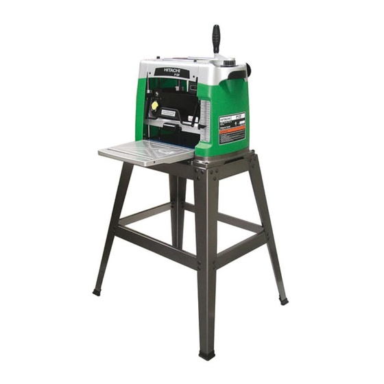
English KNOW YOUR PLANER Tool storage Depth adjustment handle ON/OFF switch Depth scale pointer Depth scale Depth lock lever Front extension table Cord brackets Carrying handle Anti-kickback pawls Main table Power cord – 10 –... -
Page 11: Assembly And Adjustments
English ASSEMBLY AND ADJUSTMENTS WARNING Never connect the plug to the power source outlet until all installations and adjustments are completed and you have read and understood the safety and operational instructions. ESTIMATED ASSEMSLY TIME 20~35 MINUTES 5. Join the front and back of stand, using short upper ASSEMBLY INSTRUCTIONS (11) and lower (10) crossbars, carriage bolts and Lift the tool from the packaging and place it on your... - Page 12 English INSTALLING THE DEPTH ADJUSTMENT HANDLE WARNING (FIG. B) 1. Place the depth adjustment handle (1) on the right To avoid injury from an accidental start-up, make sure hand side, on top of the machine. the switch is in the OFF position and the plug is not 2.
- Page 13 English ADJUSTING THE DEPTH SCALE (FIG. F) Fig. G 1. Try to plane a board. 2. Compare the measured thickness of the board to the reading on the depth scale (2). 3. If the reading on the depth scale is incorrect, loosen the screws (1) and adjust the pointer (3) until the proper measurement is displayed.
-
Page 14: Operation
English OPERATION 5. The planer works best with at least one flat WARNING surface. Place the flat surface downward on the table. Never connect the plug to the power source outlet until 6. Do not plane more than 3 mm in one pass. all installations and adjustments are completed and you 7. - Page 15 English Fig. L holes in the blade over the locating pins on the cutterhead (Fig. O). Fig. M NOTE: 1. Planing for a smooth finish as well as thickness is best accomplished by taking light cuts on the board. 2. For the best result, plane both sides of your workpiece to reach the desired thickness.
- Page 16 English 8. Slightly adjust the blade position so that it is positioned uniformly in the centre of cutterhead. 9. Replace the hold-down plate (5), screw the eight hex bolts (4) in, but do not tighten. (Fig. O) 10. Place the blade setting gauges (7) on the cutterhead with both gauges resting firmly against the blade.
-
Page 17: Maintenance
English MAINTENANCE REPLACING V-BELT WARNING Inadequate tension in the V-belt will cause the belt to slip from the motor pulley or drive pulley. A loose belt Never put lubricants on the blade while it is spinning. must be replaced. To replace V-belt: To avoid fire or toxic reaction, never use gasoline, ●... -
Page 18: Troubleshooting Guide
To avoid injury from an accidental start, turn the switch OFF and always remove the plug from the power source before making any adjustments. ● Consult Hitachi Authorized Service Center if for any reason the motor will not run. SYMPTOM... -
Page 19: Parts List
English PARTS LIST 13” (330mm) PLANER MODEL NO. P13F PARTS LIST FOR SCHEMATIC Always order by I.D. Number Parts No. I.D. Description Size Parts No. I.D. Description Size 726324 0870 EXTENTION WING ASS’Y 726529 0JQ1 HEX. HD. BOLT M10*1.5-45 726325 0874 ROLLING WHEEL 726530... - Page 20 English 13” (330mm) PLANER MODEL NO. P13F – 20 –...
- Page 21 English 13” (330mm) PLANER MODEL NO. P13F PARTS LIST FOR STAND Parts No. I.D. Description Size 726435 093B FOOT PAD 726489 0J72 FLAT WASHER 1/4*5/8-1/16 726526 0JPG HEX. HD. BOLT M6*1.0-30 726591 0KJ7 CAP HD. SQ.NECK BOLT M8*1.25-16 726620 0KRQ SERRATED TOOTHED HEXAGON FLANGE NUT M6*1.0 T=6 726621...
- Page 22 English – 22 –...
- Page 23 English – 23 –...
- Page 24 English Issued by Hitachi Koki Co., Ltd. Shinagawa Intercity Tower A, 15-1, Konan 2-chome, Minato-ku, Tokyo 108-6020, Japan Code No. C99134911 Printed in Taiwan – 24 –...