Table of Contents
Advertisement
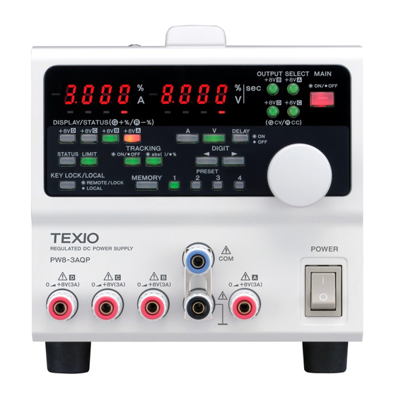
REGULATED DC POWER SUPPLY
PW-A SERIES
SERVICE MANUAL
FILTER
(B11-0597-23)
SHORTING BAR
(E29-0506-04)
KNOB, RED
(K29-7257-02)
KNOB, WHITE
(K29-7259-02)
COVER, TOP
(F07-1538-03)
RUBBER FOOT
(J02-0363-04)
KENWOOD TMI CORPORATION
© 2002-8 PRINTED IN KOREA
B51-1161-00 (K/K) PDF
FRONT PANEL
(A63-0423-12)
KNOB, ENCORDER
(K21-0907-14)
KNOB, BLUE
(K29-7260-02)
KNOB, RED
(K29-7257-02)
KNOB, BLACK
(K29-7258-02)
REAR PANEL
(A83-0231-03)
It changes by model.
Advertisement
Table of Contents

Related Manuals for Kenwood PW-A series


Summary of Contents for Kenwood PW-A series
- Page 1 REGULATED DC POWER SUPPLY PW-A SERIES KENWOOD TMI CORPORATION SERVICE MANUAL © 2002-8 PRINTED IN KOREA B51-1161-00 (K/K) PDF FILTER (B11-0597-23) FRONT PANEL (A63-0423-12) KNOB, ENCORDER (K21-0907-14) KNOB, BLUE (K29-7260-02) SHORTING BAR (E29-0506-04) KNOB, RED (K29-7257-02) KNOB, RED (K29-7257-02) KNOB, WHITE...
- Page 2 PW-A WARNING The following instructions are for use by qualified personnel only. To avoid electric shock, do not perform any servicing other than contained in the operating instructions unless you are qualified to do so. CONTENTS SPECIFICATIONS ......................3 CIRCUIT DESCRIPTION ....................15 BLOCK DIAGRAM ......................20 ADJUSTMENT ......................
-
Page 3: Channel
PW-A SPECIFICATIONS Specificat ions of PW18-1.8 AQ IT E M S A Channe l B Channe l C Ch anne l D Ch anne l 0 to + 8 V Ou tput v o ltage 0 t o 0 t o 18 0 t o 6 V Voltage setting resolution 10 mV... - Page 4 PW-A SPECIFICATIONS Specifications of PW18-1.3AT(S) ATS is with a remote sensing terminal to C channel ITE MS A Ch anne l Ch anne Ch annel Ou tput v o ltage 0 to +1 8 V 0 to 18 V 0 to +6 V Voltage setting resolution 10 m V 1 mV...
-
Page 5: Specifications
PW-A SPECIFICATIONS Specifications of PW18-3AD ITEMS Channel Channel Ou tput v o ltage 0 to +18 V 0 to 18 V Voltage setting resolution ± ( 0.5% SET +2 0 mV ) Voltage setting accuracy At 23 ± 5 af ter 30 minute ag in g ı... - Page 6 PW-A SPECIFICATIONS Specifications of PW36-1.5AD ITEMS Channel Channel Ou tput v o ltage 0 to +36 V 0 to 36 V Voltage setting resolution ± ( 0.5% SET +2 0 mV ) Voltage setting accuracy At 23 ± 5 af ter 30 minute ag in g ı...
- Page 7 PW-A SPECIFICATIONS Specifications of PW18-3ADP Channel Channel ITEMS Output voltage 0 to + 18 V 0 to + 18 V Voltage setting resolution 10 mV ± (0.5% SET +20mV) Voltage setting accuracy At 23 ± 5 ı after 30 - minute aging Output current 0 to +3A 0 to +3A...
- Page 8 PW-A SPECIFICATIONS Speci f i cat i ons of PW 18- 2 ATP ITEMS Channel Channel Channel Output voltage 0 to +36 V 0 to +18 V 0 to +8 V Voltage setting resolution 10 m V 1 m V ±...
- Page 9 PW-A SPECIFICATIONS Specifications of PW16-5ADP Channel Channel ITEMS Output voltage 0 t o +6 V 0 t o +16 V Voltage setting resolution 1 mV 10 m V ± ( 0. 5% S ET +5 mV ) ± ( 0. 5% S ET +2 0 m V ) Voltage setting accuracy At 23 ±...
- Page 10 PW-A SPECIFICATIONS Specifications of PW8-3ATP ITEMS A Channel B Ch annel C Ch annel Output voltage 0 to +8 V 0 to +8 V 0 to +18 V Voltage setting resolution 1 mV 10 mV ±( 0.5% SET +5 mV ) ±( 0.5% SET +20 mV ) Voltage setting accuracy At 23 ±5°C after 30-m inute aging...
- Page 11 PW-A SPECIFICATIONS Specifications of PW26-1AT(S) ATS is with a remote sensing terminal to C channel ITEMS A Channel B Channel C Channel Output voltage 0 to +26 V 0 to -26 V 0 to +6 V Voltage setting resolution 10 mV 1 mV ±( 0.5% SET +20 mV ) ±( 0.5% SET +5 mV )
- Page 12 PW-A SPECIFICATIONS Specifications of PW36-1.5ADP ITEMS A Ch annel B Channel Output voltage 0 to +36 V 0 to +36 V Voltage setting resolution 10 m V ±( 0.5% SET +20 mV ) Voltage setting accuracy At 23 ±5°C after 30-m inute aging Output current 0 to +1.5 A Current setting resolution...
- Page 13 PW-A SPECIFICATIONS Common Specifications of PW-A Series ITEMS Ra tin g Set delay time 0.0 to 10.0 seconds Functions Described in panels and functions and operation procedures. Grounding Positive, COM or negative grounding is possible. Protection MAIN OUTPUT key is turned off if exhaust air temperature becomes too high.
- Page 14 PW-A SPECIFICATIONS Communication Specifications of IF-40RS Local bus ( PW bus ) IN/OUT pin 3 of connector J1 Date transmission rate 9600 bps, error : 5% or less Start bit 1 [ bit] Date bit [ bit] Data code structure Parity bit [ bit] [ bit]...
- Page 15 PW-A CIRCUIT DESCRIPTION each setup. The matrix is constituted with LED with OVERVIEW OF PW-A switch, and scan is carried out from CPU. AC power input to the AC inlet of the CPU unit passes 9. Light Emitting Diode (D3-11) -- LED for each display. through the units shown below and reaches the output LED which displays the beam of output and setting terminals.
- Page 16 PW-A CIRCUIT DESCRIPTION 19, 21. Pos itive/negative change -- The polarity of a the voltage for a FAN drive is exceeded, the signal capacitor is replaced by spec code with a jumper. which turns off MAINOUTPUT will be outputted with the comparator of IC 106 1/2.
-
Page 17: Circuit Description
PW-A CIRCUIT DESCRIPTION Channels 2 and 4 use the COM commonly. In a three- outputs a "/BACK" signal. channel power supply unit, channels 1 and 2 use a 3. ROM and RAM These ROM and RAM are connected different common line from channel 3. Thus, the power with the CPU. -
Page 18: Block Diagram
PW-A CIRCUIT DESCRIPTION transistors and CV/CC REF into positive or negative CPU, ROM, RAM and so forth, AC inlet, fuse, input voltage according to the CPU and stops the output. selector switch, and AC power supply unit with Parts and voltage differ with the polarity of the output. capacitors. - Page 19 PW-A CIRCUIT DESCRIPTION External control (CN..) These are directly connected D1 to D6 are used for protection. with the CPU ports. Pin 7 has Q1 and Q2 for both input and output. PH30 is used for isolation. CN5-1 -- The MAIN OUTPUT is turned on when this terminal goes Low.
- Page 20 PW-A AC IN Y87-xxxx -xx CPU UNIT (X77-2380-xx) IF -40GU/RS/USB • CPU CIRCUIT X72-1540-xx • ExtCont TERMINAL OPTION FOR INTERFACE UNIT • AC INPUT TRANSFER POWER • IN PUT PROTECTION TRANSFORMER PANEL UNIT FUSE (X66-1820-xx) • DISPL AY LED • OPERATION SYSTEM POWER SUPP LY POWER SUPP LY SWITCH...
- Page 21 X66-1820-xx 1. ROTARY ENCODER R/E A, R/E B 2. LED ED1** 3. LED DRIVER VOLT AGE DISPLAY ED1 ~ 4, D1 4. LED ED2** 5. LED DRIVER CURRENT DISPLAY ED5 ~ 6, D2 CLK, DATA LED** 9. LED D3 ~ 11 6.
- Page 22 X68 -2210-xx X68-2210-xx X73-2320-xx AMP UNIT 1. RECTIFICATION 2. REGUL ATOR SMOOTING CIRCUIT CIRCUIT D101, C102 IC101 4. REGUL ATOR 3. RECTIFICATION CIRCUIT SMOOTING CIRCUIT IC102, 103 D102, C104, C105 6. REGUL ATOR 5. RECTIFICATION CIRCUIT SMOOTING CIRCUIT IC104, 105 D103, C107, C108 7.
- Page 23 X68 -2210-xx 17. SMOOTHING 13. RECTIFICATION ∗ CIRCUIT CIRCUIT C301 19. POSITIVE NEGATIVE 18. SMOOTHING 14. RECTIFIATION ∗ CHANGE CIRCUIT CIRCUIT W301 ~ 308 C302 15. RECTIFICATION 20. SMOOTHING 21. POSITIVE NEGATIVE CIRCUIT CIRCUIT CHANGE D401 C303 W309 ~ 316 22.
- Page 24 CHANNEL 1 CONSTANT CURRENT CIRCUIT Q1,D1 ~ 3,19 X72-1620-xx R1,2 CHANNEL 2 CONSTANT CURRENT CIRCUIT Q2,D4 ~ 9,20,21 R3,4 CHANNEL 3 CONSTANT CURRENT CIRCUIT Q3,D10 ~ 15,22,23 R5,6 CHANNEL 4 CONSTANT CURRENT CIRCUIT Q4,D16 ~ 18,24 R7,8...
- Page 25 CVCC0_A X73-2320-xx OUT0_A 8. OUT ON/OFF POWER SUPPLY UNIT 3. CC ERROR 2. REF AMPLIFICATION 1. D / A (X68-2210-**D/6) AMPLIFIER 5. POWER INVERSION CIRCUIT IC8 -1/2 TRANSISTOR IC3,4 1/2CV2/2CC INVER Q1 ~ 6 TION 6. CURREN T 4. CV ERROR POWER 10.
- Page 26 X77-2380-xx 7. OUTSIDE CONTRO L 5. ISOL ATION 2. RESET CN5, Q1, Q2 CIRCUIT PH1 ~ 29 IC 11 3. DATE 1. CPU LATCH IC7, 8, 9 4. EEPROM IC4, 5 3. LINE DECODER 6. ENCODER SIGNAL IC12, 13-3/4 IC14 -1/6, 2/6, 3/6 8.
- Page 27 X72-1540-xx CONTROL TERMINAL IC4,X1 1.CPU PH1,IC14 GP-IB GP-I B CONTROL TERMINAL IC10, 11,12 IC5,6,7,8 3.ROM LOCAL BUS LOCAL BUS CONTROL TERMINAL IC13,S1 8.ROM 3.RAM RS-232C TERMINAL RS-232C LOCAL BUS CONTROL IC18,Q1,2,3 MODULAR C17 ~ 21 TERMINAL...
- Page 28 PW-A ADJUSTMENT To ob tain the best performance, periodically calibrate TEST EQUIPMENT REQUIRED the unit. Sometimes, only one mode need be The following instrument or their equivalent should calibrated, while at other times, all modes shou ld be be used for making adjustment. calibrated.
- Page 29 PW-A ADJUSTMENT 2-2. Voltage adjustment channel setup 1. Press the V key. 2. Turn a rotary encoder and set the adjusting channel. 3. Press the MEMORY key. 4. Select the OUTPUT SELECT of the channel to adjust. 2-3. Connection of constant apparatus Connect the output CH to adjust PWA, and COM terminal to DMM.
-
Page 30: Adjustment
PW-A ADJUSTMENT MODEL NAME SETTING VOLTAGE ADJUSTMENT RANGE ± 1 mV 18.00 V ± 1 mV PW18-1.3ATS -18.00 V ± 1 mV 6.000 V ± 1 mV 26.00 V ± 1 mV PW26-1ATS -26.00 V ± 1 mV 6.000 V 2-5. - Page 31 PW-A ADJUSTMENT MODEL NAME SETTING VOLTAGE ADJUSTMENT RANGE ± 1 mV 1.800 V ± 1 mV PW18-1.3ATS -1.800 V ± 1 mV 0.600 V ± 1 mV 2.600 V ± 1 mV PW26-1ATS -2.600 V ± 1 mV 0.600 V After voltage adjustment end, when adjust other channels, adjust in the same procedure from 5-3-2.
- Page 32 PW-A ADJUSTMENT ADJUSTMENT ADJUSTMENT SHUNT MODEL NAME SETTING VOLTAGE VOLTAGE RANGE REGISTER ± 0.1 mV 100 m Ω 3.000 A 0.300 V PW18-3ADP ± 0.1 mV 100 m Ω 3.000 A 0.300 V ± 1 mV 1 Ω 1.000 A 1.000 V PW18-2ATP 1 Ω...
- Page 33 PW-A ADJUSTMENT ADJUSTMENT ADJUSTMENT SHUNT MODEL NAME SETTING VOLTAGE VOLTAGE RANGE REGISTER ± 1 mV 1 Ω 0.300 A 0.300 V PW18-3ADP 1 Ω ± 1 mV 0.300 A 0.300 V ± 1 mV 1 Ω 0.100 A 1.000 V PW18-2ATP 1 Ω...
- Page 34 POWER SUPPLY POWER SUPPLY PANEL U NIT AMP UNIT CPU UNIT MODEL NAME MODEL No. UNIT UNIT X66-1820-xx X73-2320-xx X77-2380-xx X68-2210-xx X68-2300-xx PW18-1.8AQ Y86-3090-00 PW18-1.3AT Y86-3100-00 PW18-1.3ATS Y86-3100-02 PW18-3AD Y86-3110-00 PW36-1.5AD Y86-3120-00 PW18-3ADP Y86-3130-00 PW18-2ATP Y86-3140-00 PW16-5ADP Y86-3430-00 PW8-3ATP Y86-3440-00 PW26-1AT Y86-3450-00 PW26-1ATS...
- Page 35 ✽ New Parts ✽ New Parts Parts without Parts No. are not supplied. Parts without Parts No. are not supplied. Les articles non mentionnes dans le Parts No. ne sont pas fournis. Les articles non mentionnes dans le Parts No. ne sont pas fournis. Teile ohne Parts No.
- Page 36 ✽ New Parts ✽ New Parts Parts without Parts No. are not supplied. Parts without Parts No. are not supplied. Les articles non mentionnes dans le Parts No. ne sont pas fournis. Les articles non mentionnes dans le Parts No. ne sont pas fournis. Teile ohne Parts No.
- Page 37 ✽ New Parts ✽ New Parts Parts without Parts No. are not supplied. Parts without Parts No. are not supplied. Les articles non mentionnes dans le Parts No. ne sont pas fournis. Les articles non mentionnes dans le Parts No. ne sont pas fournis. Teile ohne Parts No.
- Page 38 Les articles non mentionnes dans le Parts No. ne sont pas fournis. Teile ohne Parts No. werden nicht geliefert. Teile ohne Parts No. werden nicht geliefert. Parts No. Name & Description Parts No. Name & Description PW-A SERIES J21-9047-04 BRACKET; FET J21-9048-02 BRACKET; POWER TRANSFORMER A01-4125-01 CASE; TOP...
- Page 39 ✽ New Parts ✽ New Parts Parts without Parts No. are not supplied. Parts without Parts No. are not supplied. Les articles non mentionnes dans le Parts No. ne sont pas fournis. Les articles non mentionnes dans le Parts No. ne sont pas fournis. Teile ohne Parts No.
- Page 40 ✽ New Parts ✽ New Parts Parts without Parts No. are not supplied. Parts without Parts No. are not supplied. Les articles non mentionnes dans le Parts No. ne sont pas fournis. Les articles non mentionnes dans le Parts No. ne sont pas fournis. Teile ohne Parts No.
- Page 41 ✽ New Parts Parts without Parts No. are not supplied. Les articles non mentionnes dans le Parts No. ne sont pas fournis. Teile ohne Parts No. werden nicht geliefert. Name & Description Ref. No –00 –01 –04 –06 –08 –09 Parts No.
- Page 42 ✽ New Parts ✽ New Parts Parts without Parts No. are not supplied. Parts without Parts No. are not supplied. Les articles non mentionnes dans le Parts No. ne sont pas fournis. Les articles non mentionnes dans le Parts No. ne sont pas fournis. Teile ohne Parts No.
- Page 43 ✽ New Parts ✽ New Parts Parts without Parts No. are not supplied. Parts without Parts No. are not supplied. Les articles non mentionnes dans le Parts No. ne sont pas fournis. Les articles non mentionnes dans le Parts No. ne sont pas fournis. Teile ohne Parts No.
- Page 44 ✽ New Parts Parts without Parts No. are not supplied. Les articles non mentionnes dans le Parts No. ne sont pas fournis. Teile ohne Parts No. werden nicht geliefert. Ref. No Parts No. Name & Description RS14DB2H151J RES.METAL OXIDE FILM 1/2W R92-0670-05 RES.
- Page 45 ✽ New Parts ✽ New Parts Parts without Parts No. are not supplied. Parts without Parts No. are not supplied. Les articles non mentionnes dans le Parts No. ne sont pas fournis. Les articles non mentionnes dans le Parts No. ne sont pas fournis. Teile ohne Parts No.
- Page 46 ✽ New Parts ✽ New Parts Parts without Parts No. are not supplied. Parts without Parts No. are not supplied. Les articles non mentionnes dans le Parts No. ne sont pas fournis. Les articles non mentionnes dans le Parts No. ne sont pas fournis. Teile ohne Parts No.
- Page 47 ✽ New Parts ✽ New Parts Parts without Parts No. are not supplied. Parts without Parts No. are not supplied. Les articles non mentionnes dans le Parts No. ne sont pas fournis. Les articles non mentionnes dans le Parts No. ne sont pas fournis. Teile ohne Parts No.
- Page 48 ✽ New Parts ✽ New Parts Parts without Parts No. are not supplied. Parts without Parts No. are not supplied. Les articles non mentionnes dans le Parts No. ne sont pas fournis. Les articles non mentionnes dans le Parts No. ne sont pas fournis. Teile ohne Parts No.
- Page 49 ✽ New Parts ✽ New Parts Parts without Parts No. are not supplied. Parts without Parts No. are not supplied. Les articles non mentionnes dans le Parts No. ne sont pas fournis. Les articles non mentionnes dans le Parts No. ne sont pas fournis. Teile ohne Parts No.
- Page 50 ✽ New Parts ✽ New Parts Parts without Parts No. are not supplied. Parts without Parts No. are not supplied. Les articles non mentionnes dans le Parts No. ne sont pas fournis. Les articles non mentionnes dans le Parts No. ne sont pas fournis. Teile ohne Parts No.
- Page 51 ✽ New Parts ✽ New Parts Parts without Parts No. are not supplied. Parts without Parts No. are not supplied. Les articles non mentionnes dans le Parts No. ne sont pas fournis. Les articles non mentionnes dans le Parts No. ne sont pas fournis. Teile ohne Parts No.
- Page 52 ✽ New Parts ✽ New Parts Parts without Parts No. are not supplied. Parts without Parts No. are not supplied. Les articles non mentionnes dans le Parts No. ne sont pas fournis. Les articles non mentionnes dans le Parts No. ne sont pas fournis. Teile ohne Parts No.
- Page 53 ✽ New Parts Parts without Parts No. are not supplied. Les articles non mentionnes dans le Parts No. ne sont pas fournis. Teile ohne Parts No. werden nicht geliefert. Name & Description Ref. No –00 –01 –02 –03 –04 –05 –06 –07 –08...
- Page 54 ✽ New Parts ✽ New Parts Parts without Parts No. are not supplied. Parts without Parts No. are not supplied. Les articles non mentionnes dans le Parts No. ne sont pas fournis. Les articles non mentionnes dans le Parts No. ne sont pas fournis. Teile ohne Parts No.
- Page 55 ✽ New Parts ✽ New Parts Parts without Parts No. are not supplied. Parts without Parts No. are not supplied. Les articles non mentionnes dans le Parts No. ne sont pas fournis. Les articles non mentionnes dans le Parts No. ne sont pas fournis. Teile ohne Parts No.
- Page 56 ✽ New Parts Parts without Parts No. are not supplied. Les articles non mentionnes dans le Parts No. ne sont pas fournis. Teile ohne Parts No. werden nicht geliefert. Ref. No Parts No. Name & Description R267 RK73FB2A103J RES. CHIP (2✽1.25) 5% 1/10W R268 RK73FB2A103J...
- Page 57 SCHEMATIC DIAGRAM PW-A...
- Page 58 SCHEMATIC DIAGRAM PW-A...
-
Page 59: Schematic Diagram
SCHEMATIC DIAGRAM PW-A... - Page 60 SCHEMATIC DIAGRAM PW-A...
- Page 61 SCHEMATIC DIAGRAM PW-A...
- Page 62 PW-A Y39-4160-00...
- Page 63 SCHEMATIC DIAGRAM PW-A...
- Page 64 SCHEMATIC DIAGRAM PW-A...
- Page 65 PC BOARD (Component side view) POWER SUPPLY UNIT (X68-2210-xx) Parts side view (D/6) INPUT UNIT (X72-1620-xx) Parts side view PANEL UNIT (X66-1820-xx) Parts side view Pattern side view Refer to the schematic diagram for the value of resistors and capacitors.
- Page 66 PC BOARD (Component side view) POWER SUPPLY UNIT (X68-2210-xx) Parts side view (E/6) Parts side view (B/6) Parts side(Pattern side view) (F/6) Parts side view (C/6) Parts side(Pattern side view) (A/6) Refer to the schematic diagram for the value of resistors and capacitors.
- Page 67 PC BOARD (Component side view) POWER SUPPLY UNIT (X68-2300-xx) Parts side view (D/6) Parts side view (C/6) Parts side view (Pattern side view) (F/6) Parts side view (E/6) Parts side view (B/6) Parts side(Pattern side view) (A/6) Refer to the schematic diagram for the value of resistors and capacitors.
- Page 68 PC BOARD (Component side view) INTERFACE UNIT (X72-1540-xx) Parts side(Pattern side view) Pattern side(Parts side view) Refer to the schematic diagram for the value of resistors and capacitors.
- Page 69 PC BOARD (Component side view) CPU UNIT (X77-2380-xx) Parts side view Refer to the schematic diagram for the value of resistors and capacitors.
- Page 70 PC BOARD (Component side view) CPU UNIT (X77-2380-xx) Pattern side (Parts side view) Refer to the schematic diagram for the value of resistors and capacitors.
- Page 71 PC BOARD(Component side view) AMP UNIT (X73-2320-xx) Parts side view Parts side Pattern side Refer to the schematic diagram for the value of resistors and capacitors.
- Page 72 PW-A A product of KENWOOD TMI CORPORATION 1-16-2, HAKUSAN, MIDORI-KU, YOKOHAMA CITY 226-8525, JAPAN...