Advertisement
Quick Links
Advertisement

Related Manuals for Kenwood PR-657


Summary of Contents for Kenwood PR-657
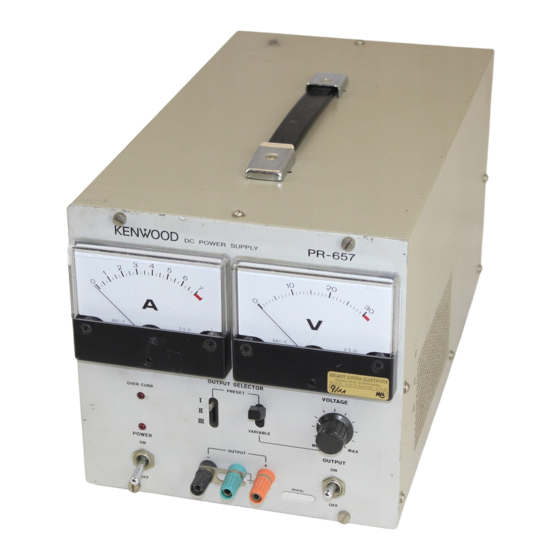
- Page 1 P R - 6 5 7 DC POWER SUPPLY INSTRUCTION MANUAL...
-
Page 2: Table Of Contents
1. GENERAL a . Your PR-657 provides advanced performance and Your PR-657 is an all solid state voltage-regulated DC high reliability as its differential amplifier is made up power supply, supplying 0 to 30 V . 7 A power. It of SC. -
Page 3: General
3. SPECIFICATIONS Power Supply Voltage regulating characteristics, Frequency and power Output voltage: 0 t o 30V. consumption: 50 to 60Hz, below 430W. Insulation resistance: Over 5 0 b e t w e e n line and Output current: 0 t o 7A. Line regulation (with cabinet (with 500VDC). -
Page 4: Circuit Description
4. CIRCUIT DESCRIPTION In studying the operation of each circuit in your PR-657, please refer to Figure 1, the "Block Diagram", and the Schematic Diagram on the back cover. C U R R E N T A M P A U X... - Page 5 Overcurrent Detector Main Power Source This detector is a protective circuit that prevents an The input A C voltage is fullwave-rectified by D1 (KBPC- overcurrent, being comprised of Q106, IC102 and Q107. 2502 bridge), is smoothed by C1 (15,000 F ) , and is fed The voltage induced across the output current detecting to the Current Amplifier.
-
Page 6: Controls And What They Do
5. CONTROLS AND WHAT THEY DO... - Page 7 LED power-on indicator, which lights when POWER ON-OFF switch is turned on. Power on-off switch, which turns on PR-657 at ON position. POWER O N / O F F Output on-off switch, which turns on output voltage is fed t o load.
-
Page 8: How To Operate
2. Set the POWER ON-OFF switch 5 t o " O N " . The power-on indicator 4 will light t o show that your PR-657 is ready for operation. 3. Adjust the V O L T A G E control 7 clockwise for a desired output voltage. - Page 9 . 5. This completes the preset voltage adjustment. Turning 2 0 V the PRESET switch 8 to " l " "JT- and " I D " - will produce the preset voltages in sequence. NOTE: The preset position out of use should be set for 0 V output voltage for safety operaiton.
- Page 10 I M P O R T A N T (3) Using Remote Control Switch Box (option) Turn the POWER ON-OFF switch t o " O F F " before To remote-control your PR-657,set up it and the remote starting set-up procedures. control switch b o x ;...
-
Page 11: Cautions For Use 1
(4)Connecting T w o or More Onits of PR-657 in Series this will cause the internal temperature t o rise, result- To use t w o units of PR-657, connect a load as illustrated ing in unstable operation and damaging of the internal below. - Page 12 8. PARTS UST OF PR-657 S C H E M A T I C D E S C R I P T I O N R E M A R K S P A R T S N O .
- Page 13 S C H E M A T I C R E M A R K S D E S C R I P T I O N P A R T S N O . • S Y M B O L CK45D2H103M Ceramic 0.01.MF'...
- Page 14 - S C H E M A T I C R E M A R K S D E S C R I P T I O N P A R T S N O . ' S Y M B O L Terminal (grey) E21-0150-03 Terminal (orange)
- Page 15 S C H E M A T I C R E M A R K S P A R T S NO. P A R T S NO. D E S C R I P T I O N SYMBOL Knob, for lever switch K 29-0208-24 Knob, for variable resistor...
- Page 16 PARIS LIST OF X65-1190-00 SCHEMATIC DESCRIPTION R E M A R K S PARTS NO. SYMBOL RESISTOR k « 1/4 W ± 5 % Carbon RD14BB2E102J R 1 0 1 , ± 5 % 1/4 W RD14BB2E331J Carbon R103 1/4 W ±...
- Page 17 SCHEMATIC R E M A R K S D E S C R I P T I O N P A R T S S Y M B O L 25 WV Electrolytic 0,47 a F CE04W1ER47 C103, 104 25 WV Electrolytic 100,uF CE04W1E101...
- Page 18 i . P. 0. BOARD...
- Page 19 10. SCHMATIC DIAGRAM The circuit elements may be changed without notice owing to a technical innovation. P R - 6 5 7...
- Page 20 KENWOOD CORPORATION 17-5, 2-chome, Shibuya, Shibuya-ku, Tokyo 150, Japan © 96002 P R ' ' ^ . D I N J A P A N B 5 0 - 2 8 3 8 - 1 0...