Table of Contents
Advertisement
Quick Links
Before operating this product, please read the instructions carefully and save this manual for
future use.
Printed in Japan
POWER
ALARM
F1
F2
F3
AMB:FILL / GRN:SOURCE
KEY
DSK
PinP
AUX
CLN
PVW
AUX BUS DELEGATION
AUX SOURCE
AUX
PGM/A
1
2
3
4
5
6
PST/B
Operating Instructions
Multi-format Live Switcher
AV-HS400AN
Model No.
1
2
TIME
WIPE
4
5
KEY
CHR KEY
7
8
F4
F5
DSK
PinP
10
11
PGM
1
2
MEMORY
XPT
USER
WIPE PATTERN / FUNCTION
MIX
WIPE
BKGD
KEY
7
8
9
10
MIX
WIPE
CUT
AUTO
Multi-format Live Switcher AV-HS400A
PAGE
3
WIPE
SQ
SL
3D
COLOR
Z
6
ON
FREEZE
BKGD PATT
POSITIONER
9
IN/OUT
KEY PATT
12
SYSTEM
FUNC
N/R
R
WIPE DIRECTION
FTB
ON
PinP
DSK
VQTB0342
Advertisement
Table of Contents

Related Manuals for Panasonic AV-HS400AN


Summary of Contents for Panasonic AV-HS400AN
-
Page 1: Operating Instructions
Before operating this product, please read the instructions carefully and save this manual for future use. Printed in Japan Operating Instructions Multi-format Live Switcher Model No. PinP AUX BUS DELEGATION AUX SOURCE USER AV-HS400AN Multi-format Live Switcher AV-HS400A PAGE WIPE TIME WIPE COLOR CHR KEY FREEZE BKGD PATT... -
Page 2: Safety Precautions
For CANADA The socket outlet shall be installed near the equipment and easily accessible or the mains plug or a power switch shall remain readily operable. A warning that an apparatus with CLASS I construction shall be connected to a MAINS... -
Page 3: Important Safety Instructions
Safety precautions IMPORTANT SAFETY INSTRUCTIONS Read these operating instructions carefully before using the unit. Follow the safety instructions on the unit and the applicable safety instructions listed below. Keep these operating instructions handy for future reference. 1) Read these instructions. 2) Keep these instructions. -
Page 4: Table Of Contents
Contents Description ... 6 Features ... 6 Precautions for use ... 7 1. Functions in each area ... 8 1-1. Control panel ...8 1-2. Crosspoint area ...9 1-3. Wipe area ...10 1-4. User button area ...11 1-5. Transition area ...12 1-6. - Page 5 Contents 4. Input/output signal settings... 61 4-1. Setting the SDI input signals and analog input signals ...61 4-1-1. Setting the frame synchronizer ...61 4-1-2. Setting the input mode ...62 4-1-3. Setting the analog input gain ...63 4-1-4. Setting the analog composite input signals ...63 4-2.
-
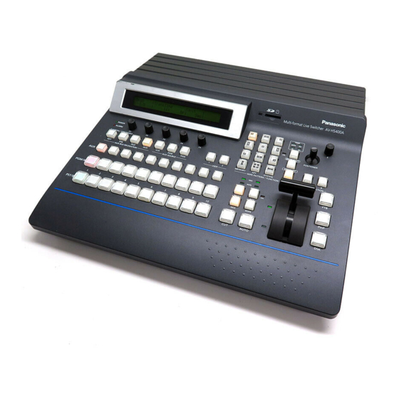
Page 6: Description
Description This is a 1 ME digital video switcher which supports a multiple number of HD and SD formats. Despite its compact dimensions, the video switcher comes standard with 4 input connectors and can support 8 input connectors when an option board is used. It also has a multi view display function that allows split-screen display with up to 10 screens. -
Page 7: Precautions For Use
Power off before connecting or disconnecting cables. Before plugging or unplugging the cables, be sure to switch power off. Avoid humidity and dust. Avoid using the product at a humid, dusty place because much humidity and dust will cause damage to the parts inside. -
Page 8: Functions In Each Area
PST/B Power indicator [POWER] This indicator lights when the power switch (_) on the rear panel is set to ON while power is supplied to the AC power input socket. It goes off when the power switch (_) is set to OFF. -
Page 9: Crosspoint Area
AUX bus crosspoint buttons (7). The indicator of the button that was pressed lights. [KEY]: Press this button to switch the AUX bus crosspoint buttons to the key fill bus or key source bus. (Each time the button is pressed, the key fill bus or key source bus is selected alternately. When the key fill bus is selected, the indicator of the button lights in amber, and when the key source bus is selected, it lights in green.) -
Page 10: Wipe Area
The indicator of the selected button lights in amber. 9 BKGD, KEY pattern selector buttons These buttons are used to switch the wipe pattern selection. The wipe pattern of a background transition is selected when the indicator of the [BKGD PATT] button is lighted after it was pressed. -
Page 11: User Button Area
1. Functions in each area 1-4. User button area = User buttons [USER 1, USER 2] These are used to allocate some functions of the menu settings to the USER 1 button and USER 2 button. See 5-3-1. USER... -
Page 12: Transition Area
B [MIX] button This is used to switch the A and B bus images while making them overlap. During the transition, the A and B bus output total is kept at 100 %. When the [MIX] button is pressed and it is selected, its indicator lights in amber. - Page 13 1. Functions in each area D [AUTO] button This is used to automatically execute transitions (auto transition) using the transition time which has been set. During auto transition its indicator lights in amber. When the button is pressed again during auto transition, the auto transition operation is suspended, and the indicator lights in green.
-
Page 14: Lcd Menu Area
For details on the operations, refer to the sections in “3. Basic operations”. [F1]: Rotate this rotary encoder to switch the sub menu. [F2] to [F5]: Rotate these rotary encoders to set the parameters. When the down arrow (↓) is shown at a menu item, its parameter is set by pressing the corresponding rotary encoder. -
Page 15: Positioner Area
Camera control X: Pan control or focus control Y: Tilt control or zoom control Rotary encoder Size adjustments Hold switch down to (size increased by rotating restore initial values (X/Y, the encoder clockwise and reduced by rotating it counterclockwise) —... -
Page 16: Sd Memory Card Area
Do not turn off the unit’s power or eject the SD memory card while the access LED is lighted. Doing so can damage the data on the SD memory card. Concerning the recommended SD memory cards Use of the following SD memory cards made by Panasonic Corporation is recommended. RP-SD128B, RP-SD256B, RP-SDR512, RP-SDR01G, RP-SDM02G ... -
Page 17: Rear Panel Connections Area
1. Functions in each area 1-9. Rear panel connections area OUTPUTS SLOT2 SLOT1 DVI/ANALOG OUTPUTS SLOT ANALOG OUTPUTS SLOT SDI OUTPUTS R SDI signal input connectors [SDI INPUTS 1 to 4] SDI signal input OUT: active through output (Use this as a monitor output application.) S Optional input connector SLOT1 [INPUTS 5, 6] (optional) T Optional input connector SLOT2 [INPUTS 7, 8] (optional) A board (with built-in up-converter), whether an SDI input board, analog input board, DVI input board or analog... - Page 18 If a 3-point power outlet is not available for this connection, be absolutely sure to consult your dealer. _ Power switch This is used to turn the power on and off.
-
Page 19: System
Analog composite input 2 lines AV-HS04M6 Analog component output 2 lines AV-HS04M4 DVI-I output 1 line AV-HS04M5 Analog component output 1 line SDI output 2 lines AV-HS04M7 AV-HS400AN VIDEO OUTPUT Output Matrix PGM1, 2(SDI) OUTPUT1(SDI) OUTPUT2(SDI) OUTPUT SLOT1(Option) OUTPUT3 OUTPUT4... -
Page 20: Connections
SLOT1 SLOT SLOT SDI OUTPUTS SDI INPUTS HD SDI HD SDI monitor HD SDI HD SDI monitor HD SDI HD SDI monitor Multi-Format Live Switcher AV-HS400AN POWER INPUTS SLOT2 SLOT1 SLOT ~IN SLOT RS-422 TALLY SIGNAL Power cord (AC 100 V to 120 V, 50/60 Hz) - Page 21 HD component monitor HD SDI HD SDI monitor DVI or VGA PC monitor Multi-Format POWER SLOT2 Live Switcher SLOT1 AV-HS400AN DVI-I SLOT ~IN SLOT RS-422 TALLY SIGNAL Power cord (AC 100 V to 120 V, 50/60 Hz) HD Component HD component...
-
Page 22: Basic Operations
3. Basic operations 3-1. Background transition 3-1-1. Selecting the bus Press the crosspoint buttons to select the material which will be targeted for the background transition. By pressing these buttons, the signals are selected, and the indicators of the selected buttons light. The color in which the button indicators light differs depending on the operation status. -
Page 23: Selecting The Transition Mode
3. Basic operations 3-1-3. Selecting the transition mode Press the [BKGD] button in the transition area so that its indicator lights in amber. When the [BKGD] button and [KEY] button are pressed at the same time, both buttons are selected. Use the [MIX] and [WIPE] buttons in the transition area to select the background transition mode. -
Page 24: Wipe
3. Basic operations 3-2. Wipe 3-2-1. Selecting the wipe pattern The wipe patterns which are allocated to the 12 wipe pattern buttons are used as the basis for wiping, and each button has four pages — wipe, squeeze, slide and 3D — of patterns. (Refer to the table of wipe patterns.) Displayed for each wipe pattern selector button are an image of the basic wipe pattern and a number. -
Page 25: Selecting The Wipe Direction
To call the preset color Turn [F5] to select the preset color using the Load item, and press the [F5] switch. The Hue, Sat and Lum values are changed to the preset color values. To save the values that were set before calling the preset color, refer to “3-10. -
Page 26: Setting The Wipe Start Position
3. Basic operations 3-2-4. Setting the wipe start position Any start position can be set for wipe pattern WIPE and SQ #5. The start position has one set of values for a background pattern and another set for a key pattern. 1 Press the [FUNC] button to light its indicator, and press the [WIPE] button to display the WIPE menu. -
Page 27: Modifying Wipe
3. Basic operations 3-2-5. Modifying wipe Setting the lighting effect Lighting effects can be added when the following wipe patterns have been selected: 3D page: #1, #3, #7, #9 1 Press the [FUNC] button to light its indicator, and press the [WIPE] button to display the WIPE menu. 2 Turn [F1] to display the Modify sub menu. -
Page 28: Key
3. Basic operations 3-3. Key This operation combines the background image with another image. The key definition can be adjusted, and an edge can be added to the combined image. Also available as materials besides KEY for combining with the background image are PinP (picture in picture) and DSK (downstream key). -
Page 29: Selecting The Key Type
3. Basic operations 3-3-1. Selecting the key type 1 Press the [FUNC] button to light its indicator, and press the [KEY] button to display the KEY menu. 2 Turn [F1] to display the KEY sub menu. 3 Turn [F2] to select the Type item. <Menu display>... -
Page 30: Selecting The Key Material
Selecting the key fill and key source signals Press the KEY button in the AUX bus selection area, and switch the selection of the key fill signal (indicator lights in amber) and key source signal (indicator lights in green). -
Page 31: Key Transitions
3. Basic operations 3-3-3. Key transitions 1 Select key in the transition mode. Press the [KEY] button in the transition area to light its indicator. To execute a background transition and key transition at the same time, press the [BKGD] button and [KEY] button together to turn on both indicators. -
Page 32: Key Preview
3. Basic operations 5 Execute the transition. Press the [AUTO] button to execute the transition automatically for the transition time which has been set. Alternatively, execute the transition manually by operating the fader lever. When the KEYAuto function has been assigned to the [FTB] button, the transition will be executed automatically for the transition time which has been set when the [FTB] key is pressed no matter which transition mode has been selected. -
Page 33: Adjusting The Chroma Key
Aspect: Change the aspect ratio of the sample marker. 4 When the [F5] switch or the rotary encoder [Z] is pressed, the hue component of the area selected by the marker is sampled. 5 On completion of the sampling, the sampled values are reflected on the Adjust1 and Adjust2 sub menus, and a chroma key combined image is output to preview. - Page 34 3. Basic operations Adjusting the chroma key 1 Press the [FUNC] button to light its indicator, and press the [CHR KEY] button to display the CHR KEY menu. 2 Turn [F1] to display the Adjust1 sub menu, and turn [F2] to [F5] to set the items. <Menu display>...
- Page 35 3. Basic operations Making other adjustments Perform the key density and key invert settings. 1 Press the [FUNC] button to light its indicator, and press the [KEY] button to display the KEY menu. 2 Turn [F1] to display the Adjust sub menu. <Menu display>...
-
Page 36: Key Decorations
To call the preset color Turn [F5] to select the preset color using the Load item, and press the [F5] switch. The Hue, Sat and Lum values are changed to the preset color values. To save the values that were set before calling the preset color, refer to “3-10. -
Page 37: Masking The Key Signals
3. Basic operations 3-3-8. Masking the key signals These steps are taken to mask the key signals using the mask signal of the box pattern. 1 Press the [FUNC] button to light its indicator, and press the [KEY] button to display the KEY menu. 2 Turn [F1] to display the Mask sub menu. -
Page 38: Flying Key
3. Basic operations 3-3-9. Flying key Using DVE effects, this key enables the key signals that have been input to be moved, expanded or contracted. In order for the flying key to take effect, select SL #5 as the key transition. When the key transition is executed, the keys are combined by the key signals set using the flying key menu. -
Page 39: Pinp (Picture In Picture)
3. Basic operations 3-4. PinP (picture in picture) Another image can be combined with the background image. 3-4-1. Selecting the PinP material Press the [PinP] button among the AUX bus selector buttons to light its indicator, and press one of the AUX bus crosspoint buttons 1 to 10 to select the PinP signal. -
Page 40: Pinp Adjustments
3. Basic operations 3-4-4. PinP adjustments Adjusting the PinP position and size While the PinP menu is selected, adjust the X and Y coordinates using the positioner in the positioner area, and adjust the size using the rotary encoder [Z]. Alternatively, the settings can be performed on the menus. 1 Press the [FUNC] button to light its indicator, and press the [PinP] button to display the PinP menu. -
Page 41: Pinp Decorations
To call the preset color Turn [F5] to select the preset color using the Load item, and press the [F5] switch. The Hue, Sat and Lum values are changed to the preset color values. To save the values that were set before calling the preset color, refer to “3-10. -
Page 42: Trimming Settings
3. Basic operations 3-4-6. Trimming settings 1 Press the [FUNC] button to light its indicator, and press the [PinP] button to display the PinP menu. 2 Turn [F1] to display the Trim sub menu. <Menu display> Trim Trim Manual Free Pair Manual 3 Turn [F2] to select the trimming type using the Trim item. -
Page 43: Dsk (Downstream Key)
3. Basic operations 3-5. DSK (downstream key) Characters or other images can be combined with the background image. 3-5-1. Selecting the DSK type 1 Press the [FUNC] button to light its indicator, and press the [DSK] button to display the DSK menu. 2 Turn [F1] to display the DSK sub menu. -
Page 44: Selecting The Dsk Material
Selecting the DSK fill signal and DSK source signal Press the [DSK] button in the AUX bus selection area to switch the selection of the DSK fill signal (indicator lights in amber) and DSK source signal (indicator lights in green). -
Page 45: Dsk Transitions
3. Basic operations 3-5-3. DSK transitions 1 Set the duration of the transition. On the TIME menu, turn [F1] to display the DSK sub menu. As with a background transition, set the transition time. 2 When the [DSK] button in the transition area is pressed, the DSK image is combined (fade-in) for the transition time which was set. -
Page 46: Dsk Decorations
To call the preset color Turn [F5] to select the preset color using the Load item, and press the [F5] switch. The Hue, Sat and Lum values are changed to the preset color values. To save the values that were set before calling the preset color, refer to “3-10. -
Page 47: Masking The Dsk Signals
3. Basic operations 3-5-7. Masking the DSK signals These steps are taken to mask the DSK signals using the mask signal of the box pattern. 1 Press the [FUNC] button to light its indicator, and press the [DSK] button to display the DSK menu. 2 Turn [F1] to display the Mask sub menu. -
Page 48: Ftb (Fade To Black)
3. Basic operations 3-6. FTB (fade to black) The user can fade out from a program image to the black screen or fade in to a program image from a black screen. 1 Set the duration of the transition. On the TIME menu, turn [F1] to display the FTB sub menu. As with a background transition, set the transition time. -
Page 49: Internal Color Signals
2 Turn [F2], [F3] and [F4] to perform the color adjustments (Hue, Sat and Lum). Calling the preset colors Turn [F5] to select the preset color using the Load item, and press the [F5] switch. The Hue, Sat and Lum values are changed to the preset color values. -
Page 50: Freezing The Input Signals
Frame or Field can also be selected while an image is frozen. 4 Press the [F5] switch to freeze the input image or cancel the freeze. If the [F5] switch is pressed while the display is “Off”, the video signal is frozen, and the display is set to “On”. -
Page 51: Switching The Aux Output
3. Basic operations 3-9. Switching the AUX output The user can switch the AUX output signals. The signals of any of the AUX bus crosspoint button 1 to 10, PGM (program) signals, PVW (preview) signals or CLN (clean) signals can be selected for output to the AUX bus. -
Page 52: Preset Memory
3. Basic operations 3-10. Preset memory Up to 10 panel settings can be stored in this memory. The table below lists the settings which are stored. <Table of stored preset memory> Item A bus Crosspoint B bus KEY FILL bus KEY SOURCE bus PinP bus DSK FILL bus... - Page 53 3. Basic operations Item Key type (Type) Luminance key setting Key adjustment (Adjust) Invert Fill type Fill matte Edge color Edge type Edge width Edge direction Key out pattern (OutPatt) Mask Mask invert Mask setting Flying key position, size Chroma key reference color Chroma key Extent of Y component effect (Y-Infl) Chroma key range...
- Page 54 2 Turn [F1] to display the PSMEM sub menu. 3 Turn [F2], select “Store” using the Mode item, turn [F3], and set the preset memory number using the NO.Sel item. 4 Press the [F5] switch (Exec) to store the settings. <Menu display> PSMEM Mode NO.Sel...
-
Page 55: Frame Memories
Even during review display, the next image can be imported. Off: No review display. 5 Press the [F5] switch (Exec) to import the still images to the frame memory. The still images can also be imported using the user buttons. -
Page 56: Sd Memory Cards
3. Basic operations 3-12. SD memory cards The unit’s frame memory data and system data can be stored on SD memory cards. Conversely, this data can be loaded from the SD memory cards to the unit. Frame memory data (still image data): The unit supports 24-bit (uncompressed) BMP (bitmap) and JPEG (baseline) is the only file formats. -
Page 57: Initializing The Sd Memory Cards
Select Init If “Load”, “Save” or “Delete” is selected and then the [F2] switch is pressed after a SD memory card not formatted in compliance with the SD standard has been inserted, a message indicating that “This card is not usable Please initialize it”... -
Page 58: Saving Data On Sd Memory Cards
FMEM1, 2: Still image data of frame memory 1, frame memory 2 System: System data 5 If the [F5] switch is now pressed, the file is stored on the SD memory card. (Filenames are allocated automatically.) System data: “HS400/SYSTEM” folder Still image data: “HS400/IMAGE”... -
Page 59: Loading Data From Sd Memory Cards
5 Using the LoadFile item, turn [F4] to select the name of the file to be loaded. 6 If the [F5] switch is now pressed, the file is loaded from the SD memory card and stored in the unit’s internal memory. -
Page 60: Deleting Files On Sd Memory Cards
“Over100” is displayed when an attempt is made to store 101 or more files. FreeSpace: The SD memory card’s total memory and remaining free space are displayed. (Free space/card’s total memory) 3 Press the [F5] switch, and the display of information of Images item and FreeSpace item is updated. DelFile? HS070531100000 Yes↓... -
Page 61: Input/Output Signal Settings
4. Input/output signal settings 4-1. Setting the SDI input signals and analog input signals The user can set the SDI input signals and analog input signals. IN5 to IN8 can be set only when one of the following optional boards has been connected: SDI input board Analog input board Analog composite input board... -
Page 62: Setting The Input Mode
1 On the Input sub menu, turn [F2] to select the input signals using the Signal item. 2 Turn [F4] to set the input mode using the Mode item, and press the [F4] switch to enter the selection. An asterisk () appears at the left of the input mode currently selected. -
Page 63: Setting The Analog Input Gain
4. Input/output signal settings 4-1-3. Setting the analog input gain When the analog input board (option) has been connected, the gain of the input signals can be set. Alternatively, when the analog composite input board (option) has been connected, the gain of the Y signals can be set. -
Page 64: Setting The Up-Converter (Option)
IN5-8 3 Turn [F2] to select the input signal using the Signal item. 4 Turn [F3] to select the scaling system using the Scale item, and press the [F3] switch to enter the selection. SQ (squeeze): The image is enlarged both horizontally and vertically to fill the entire screen. -
Page 65: Setting The Dvi Input Signals (Option)
4. Input/output signal settings 4-3. Setting the DVI input signals (option) 4-3-1. Setting the DVI input signals The user can set the DVI input signals when the DVI input board (option) has been connected. Signals with the following resolutions can be input. If signals with any other resolution or frequency are input, the picture will turn black. - Page 66 4. Input/output signal settings <DVI input scaling size table> DVI format Mode Fit-V 1024768 Fit-H Full SXGA Fit-V 12801024 Fit-H Full WXGA Fit-V 1280768 Fit-H Full HD/1080i HD/720P 1920 1080 1280 720 : Black images are inserted here. : The parts of the images protruding in these areas are cropped.
-
Page 67: Adjusting The Dvi Input Signals
4. Input/output signal settings 4-3-2. Adjusting the DVI input signals Adjust the clock/phase and position of the DVI input signals. 1 Press the [FUNC] button to light its indicator, and press the [IN/OUT] button to display the IN/OUT menu. 2 Turn [F1] to display the DVIPhs sub menu. <Menu display>... -
Page 68: Setting The Output Signals
4. Input/output signal settings 4-4. Setting the output signals 4-4-1. Types of output signals There are five output signal types: PGM, PVW, AUX, MULTI and KEYOUT. Five lines of output signals can be assigned to OUTPUT1 to 6. PGM: This is the main-line output of the switcher; images with wipe, mix, key and other effects added to them are output. -
Page 69: Assigning The Output Signals
4 When the SDI output board (option) has been connected, turn [F4] to set the output mode using the Mode item, and press the [F4] switch to enter the setting. An asterisk () appears on the left of the currently selected output mode. -
Page 70: Setting The Sync Signals
BBAD 0IRE 3 Turn [F2], select the sync signal using the Sync item, and press the [F2] switch to enter the selection. An asterisk () appears at the left of the reference signal currently selected. 4 Turn [F3] to select the setup level of the black burst signal in the internal synchronization mode using the BBSetup item. -
Page 71: Adjusting The Output Signal Phase
4. Input/output signal settings 4-6. Adjusting the output signal phase The phase of the output video signals can be adjusted. 1 Press the [FUNC] button to light its indicator, and press the [IN/OUT] button to display the IN/OUT menu. 2 Turn [F1] to display the OutPhs sub menu. <Menu display>... - Page 72 4. Input/output signal settings <Phase adjustment setup> (System standard) • 1H Output (+1H) Shortest Output (+0.5H) • 0H Output (1F delay for REF and in-phase output) FS Range MAX less than approximately 1 frame H Phase (–0.5H to +0.5H) + V Phase vertical (100 lines) AVDL Range: Range for automatic phase adjustment.
- Page 73 4. Input/output signal settings <Phases and delay amounts of input/output signals during HD format use> Frame synchronizer On, Off Mode: Input Normal, UC or signals D by D (cannot be selected when the system format is 720p) See 4-1-1. When the 1080/59.94i format is used: ...
- Page 74 4. Input/output signal settings <Phase relationship between input signals and output signals> (for 1080/59.94i format) (Example 1) Input signals (non-synchronized) Sync signal (Ref) Output signal 1 Max. 1F Output signal 2 (90H) Max. 1F+90H Output signal 2 (1F) (Example 2) Input signals (non-synchronized) Sync signal (Ref)
-
Page 75: Setting The Multi View Display
4. Input/output signal settings 4-7. Setting the multi view display The input images, program images and preview images can be output side by side on one screen on the external monitor. 4-7-1. Setting the screen layout The multi view display has three display modes: 10-division mode, 4-division mode and 8-division mode. Inputs 1 to 8, frame memory and color background can be assigned to sub screens 1 to 8. -
Page 76: Input/Output Signal Settings
4. Input/output signal settings 1 Press the [FUNC] button to light its indicator, and press the [IN/OUT] button to display the IN/OUT menu. 2 Turn [F1] to display the Multi1 sub menu. <Menu display> Multi1 Split 6/15 10Split 4Split 8Split 3 Turn [F2] to select the display mode using the Split item. -
Page 77: Setting The Split Frame And Characters
4. Input/output signal settings 4-7-2. Setting the split frame and characters Set the frame, character brightness and background of the split screens to be displayed on the multi view display. 1 Press the [FUNC] button to light its indicator, and press the [IN/OUT] button to display the IN/OUT menu. 2 Turn [F1] to display the Multi2 sub menu. -
Page 78: Changing The Material Names
3 Turn [F2] to select the input signals using the Signal item. 4 Turn [F3] to select the type of material name using the Type item, and press the [F3] switch to enter the type. An asterisk () appears at the left of the type of material name currently selected. -
Page 79: Setting The On-Screen Display (Osd)
4. Input/output signal settings 4-8. Setting the on-screen display (OSD) The menu screen is superimposed on the preview output or multi view display output for display. 1 Press the [FUNC] button to light its indicator, and press the [IN/OUT] button to display the IN/OUT menu. 2 Turn [F1] to display the OSD sub menu. -
Page 80: Setting The Dvi Output Signals (Option)
If it is off, adjust the position at the monitor. For details on the adjustment method, refer to the operating instructions of the monitor. 5 Turn [F4] to select the resolution of the images to be output, and press the [F4] switch to enter the selection. Auto: The equipment information of the output destination is captured by the DVI signals, and the images are output at the optimum resolution. -
Page 81: Setting The Ancillary Data
4. Input/output signal settings 4-10. Setting the ancillary data In this section, the function for allowing the ancillary data of the SDI input signals to pass through is set. If SD format signals are input while the HD format has been set as the system format, it will not be possible for their ancillary data to be passed through. -
Page 82: Setting The Down-Converter
The aspect ratio is maintained, the image is reduced in size in line with the horizontal resolution, and a black image is added at the top and bottom. System image (HD) 5 Turn [F4] to set the delay time of the output using the Delay item, and press the [F4] switch to enter the setting. 90H (75H): When the system format is 1080/59.94i, the image is delayed from the system image (HD) by 90H, and... -
Page 83: System Settings
2 Turn [F1] to display the Format sub menu. 3 Turn [F2], select the format using the Mode item, and press the [F2] switch to enter the selection. An asterisk () appears at the left of the format currently selected. -
Page 84: Setting The Crosspoints
5. System settings 5-2. Setting the crosspoints 5-2-1. Assigning signals to the crosspoints External video input signals and internally generated signals can be assigned to crosspoint buttons 1 to 10. Displaying the assignment statuses 1 Press the [FUNC] button to light its indicator, and press the [XPT] button to display the XPT menu. 2 Turn [F1] to display the XPTStats sub menu. -
Page 85: Setting The Crosspoint Switching
5. System settings The table below lists the default settings. Button Signal BLACK INPUT1 INPUT2 INPUT3 INPUT4 INPUT5 INPUT6 INPUT7 INPUT8 XP10 CBGD If the optional board has not been connected, black images are input for INPUT5 to 8. 5-2-2. Setting the crosspoint switching The timing at which the crosspoints are to be switched can be set. -
Page 86: Button Assignments
5. System settings 5-3. Button assignments 5-3-1. Setting the user buttons The user can assign several functions which can be set using the menu items into two user buttons (USER 1 and USER 2). The user buttons light in amber when the assigned function is ON and are off when the assigned function is OFF. Each time the user button is pressed, the function setting alternates between ON and OFF. -
Page 87: Setting The Date And Time
3 Turn [F2] to set the year using the Year item. 4 Turn [F3] to set the month using the Month item. 5 Turn [F4] to set the day using the Date item. 6 Press the [F5] switch to enter the year/month/day. <Menu display> Date... -
Page 88: Network Settings
1 Press the [FUNC] button to light its indicator, and press the [SYSTEM] button to display the SYSTEM menu. 2 Turn [F1] to display the Network1 sub menu. 3 Turn [F2] to [F5] to set the IP address, and press the [F5] switch (Save) to enter the address. <Menu display>... -
Page 89: Other Settings
5. System settings 5-6. Other settings 5-6-1. Setting the LCD backlight The LCD backlight can be set to ON or OFF. 1 Press the [FUNC] button to light its indicator, and press the [SYSTEM] button to display the SYSTEM menu. 2 Turn [F1] to display the System sub menu. -
Page 90: Setting The Gpi
5. System settings 5-6-4. Setting the GPI The user can set the functions that are to be controlled from the GPI ports and set whether to enable the control. 1 Press the [FUNC] button to light its indicator, and press the [SYSTEM] button to display the SYSTEM menu. 2 Turn [F1] to display the GPI sub menu, and turn [F2] to set the function to be controlled by the GPI port 1 using the GPI1 item. -
Page 91: Camera Control
5. System settings 5-7. Camera control A camera and pan-tilt head can be controlled from this unit. Up to five cameras can be controlled via a controller (AW-RP655N or AW-RP555N) connected to the unit’s RS- 422 interface connector. The unit can also be connected directly to a pan-tilt head, and the camera and pan-tilt head can be controlled. To control a camera in this way, select “P/TCont”... - Page 92 SLOT SLOT ANALOG OUTPUTS ANALOG INPUTS SDI INPUTS SLOT SLOT SDI OUTPUTS SDI INPUTS RS-422 AV-HS400AN Cable length: Max. 656 ft. (200 m) Twisted pair cable (AWG24) <Connection specifications> AV-HS400AN Pin No. Signal FRAME GND TXD – RXD + TXD + RXD –...
- Page 93 DVI/ANALOG OUTPUTS DVI INPUTS DVI-I DVI-I DVI-I SLOT ANALOG OUTPUTS ANALOG INPUTS SLOT SDI OUTPUTS SDI INPUTS RS-422 AV-HS400AN <Connection specifications> AV-HS400AN Pin No. Signal FRAME GND TXD – RXD + TXD + RXD – FRAME GND RS-422 When the AW-HE100N is to be connected to the unit, select a setting which will enable operations to be controlled by the controller in the “Controller”...
- Page 94 DVI-I SLOT SLOT ANALOG OUTPUTS ANALOG INPUTS SLOT SLOT SDI OUTPUTS SDI INPUTS RS-422 AV-HS400AN Cable length: Max. 656 ft. (200 m) Twisted pair cable (AWG24) <Connection specifications> AV-HS400AN Pin No. Signal FRAME GND TXD – RXD + TXD + RXD –...
- Page 95 5. System settings Camera control settings 1 Press the [FUNC] button to light its indicator, and press the [SYSTEM] button to display the SYSTEM menu. 2 Turn [F1] to display the CamCTL1 sub menu. <Menu display> CamCTL1 Signal 3/16 IN1-8 None 3 Turn [F2] to select the input signal using the Signal item.
- Page 96 Control is exercised at the slowest speed. : When controlling the pan-tilt head’s power to On, turn [F5] to select On, and press the [F5] switch. When controlling it to Off, turn [F5] to select Off, and press the [F5] switch.
-
Page 97: Status Displays
5. System settings 5-8. Status displays 5-8-1. Alarm status displays These displays indicate a trouble status (alarm) in the power supply or fan. 1 Press the [FUNC] button to light its indicator, and press the [SYSTEM] button to display the SYSTEM menu. 2 Turn [F1] to display the Alarm sub menu. -
Page 98: Displaying The Version Information And Option Information
5. System settings 5-8-2. Displaying the version information and option information Information on the unit’s software and hardware versions and the statuses of the options are displayed. 1 Press the [FUNC] button to light its indicator, and press the [SYSTEM] button to display the SYSTEM menu. 2 Turn [F1] to display the MainVer sub menu. -
Page 99: Initialization
3 Press [F2] to initialize the settings. The “Init?” message appears. 4 To initialize the settings, turn [F2] to select YES, and then press the [F2] switch. To cancel the initialization, turn [F2] to select No, and then press the [F2] switch. -
Page 100: External Interfaces
• Wipe pattern selection (BKGD) • Transition mode (MIX/WIPE) selection • Auto transition time setting • Auto transition execution <Table of wipe patterns supported> GVG protocol GVG protocol AV-HS400AN WIPE #1 WIPE #2 WIPE #3 WIPE #4 WIPE #5... -
Page 101: Gpi Connector
6. External interfaces 6-2. GPI connector These connectors enable the unit to be controlled from an external source. Signals are input using contacts. The following types of control are exercised using the contacts as triggers. Use stereo mini plugs with a 3.5 mm diameter for connection to the unit. -
Page 102: Tally Connector
GROUND Pins 1 to 9 must satisfy the following conditions: Dielectric strength: Max. DC 24 V Current: Max. 50 mA Example of tally connections AV-HS400AN Tally, Alarm output (IN1 to 8, ALARM) (Max. current: 50 mA) GROUND Input/output Open collector output... -
Page 103: Image Transmission Functions
7. Image transmission functions This unit comes with a function for transmitting still images from the host computer to the unit via LAN and a function for importing still images from the unit into the host computer. The image transmission software must be installed in the host computer from the CD-ROM supplied in order to use these functions. -
Page 104: How To Install The Software
7. Image transmission functions How to install the software This section describes how to install the image transmission software (HS400 Tool). Windows XP is used as the host computer’s operating system in the example given here. 1. Insert the CD-ROM supplied with the unit into the CD-ROM drive of the host computer in which the program will be installed. - Page 105 7. Image transmission functions Operation This section describes how to operate the image transmission software (HS400 Tool). <Startup> On the Start menu of Windows, select [Programs] [Panasonic] [AV-HS400Tool] [HS400Tool]. The main screen now appears. <Exit> Click the [CLOSE] button.
- Page 106 7. Image transmission functions <Transmitting images to the unit> 1. Select the mode. Check that “To HS400” appears in the [Mode] field. If “From HS400” appears instead, click the [From HS400] button so that “To HS400” appears. 2. Select the transmission destination of the images in the [Target] field. FMEM1: Unit’s frame memory 1 FMEM2: Unit’s frame memory 2 3.
- Page 107 7. Image transmission functions <Transmitting images from the unit> 1. Select the mode. Check that “From HS400” appears in the [Mode] field. If “To HS400” appears instead, click the [To HS400] button so that “From HS400” appears. 2. Select the images to be imported to the host computer in the [Target] field. FMEM1: Images in unit’s frame memory 1 FMEM2: Images in unit’s frame memory 2 3.
-
Page 108: Setting Menu Table
8. Setting menu table A setting is entered when an item displayed (↓) is selected and then the [F1], [F2], [F3], [F4] or [F5] switch is pressed. (It will not be entered unless the switch is pressed.) Sub menu Menu Turn F1 to select. - Page 109 8. Setting menu table Sub menu Menu Turn F1 to select. Parameter Setting range Default value Adjust Parameter Setting range Default value FillMatt Parameter Setting range Default value Edge Parameter Setting range Default value EdgeCol Parameter Setting range Default value Mask Parameter Setting range...
- Page 110 8. Setting menu table Sub menu Menu Turn F1 to select. Parameter Setting range Default value Adjust Parameter Setting range Default value FillMatt Parameter Setting range Default value Edge Parameter Setting range Default value EdgeCol Parameter Setting range Default value Mask Parameter Setting range...
- Page 111 8. Setting menu table Sub menu Menu Turn F1 to select. IN/OUT Input Parameter 1/15 Setting range Default value Output Parameter 2/15 Setting range Default value Parameter 3/15 Setting range Default value OutPhs Parameter 4/15 Setting range Default value Parameter 5/15 Setting range Default value...
- Page 112 8. Setting menu table Sub menu Menu Turn F1 to select. IN/OUT DVIOut Parameter 12/15 Setting range Default value UpConvt Parameter 13/15 Setting range Default value CmpsitIn Parameter 14/15 Setting range Default value DownConv Parameter 15/15 Setting range Default value MEMORY PSMEM Parameter...
- Page 113 8. Setting menu table Sub menu Menu Turn F1 to select. SYSTEM Format Parameter 1/16 Setting range Default value System Parameter 2/16 Setting range Default value CamCTL1 Parameter 3/16 Setting range Default value CamCTL2 Parameter 4/16 Setting range Default value Button Parameter 5/16...
- Page 114 8. Setting menu table Sub menu Menu Turn F1 to select. SYSTEM Date Parameter 13/16 Setting range Default value Time Parameter 14/16 Setting range Default value MainVer Parameter 15/16 Setting range OptVer Parameter 16/16 Setting range Parameter 1 Parameter 2 Turn F2 to select.
-
Page 115: Appearance
9. Appearance SIGNAL ~IN POWER POWER ALARM AMB:FILL / GRN:SOURCE PGM/A PST/B TALLY RS-422 INPUTS SLOT INPUTS ANALOG SLOT DVI-I DVI-I INPUTS SLOT1 SLOT2 INPUTS TIME WIPE CHR KEY PinP PinP MEMORY AUX BUS DELEGATION AUX SOURCE USER WIPE PATTERN / FUNCTION WIPE BKGD WIPE... -
Page 116: Specifications And Standard Accessories
10. Specifications and standard accessories Specifications Inputs 8 video input lines (maximum) 4 standard video input lines: SDI inputs 4 Maximum of an additional 4 video input lines as options: SDI inputs 2, analog component (HD/SD) inputs 2, DVI inputs 2, analog composite inputs 2 Up to two optional boards from among the various optional input boards (incorporating two up-converter lines) can be additionally connected. - Page 117 10. Specifications and standard accessories SDI outputs HD: Serial digital (SMPTE 292M) SD: Component digital (SMPTE 259M) BNC connector, PGM 1 (2 outputs), OUTPUT 1 to 6, up to 6 lines OUTPUT 3 to 6 are optional outputs. HD [SMPTE 292M (BTA S-004B) standard complied with] •...
-
Page 118: Standard Accessories
10. Specifications and standard accessories Control I/O LAN (10BASE-T) Serial communication interface Tally output External media SD memory cards Ambient operating 32 °F to 104 °F (0 °C to 40 °C) temperature Humidity 10 % to 90 % (no condensation) Power supply AC 100 V - 120 V, 50/60 Hz Power consumption... -
Page 119: Appendix (Glossary)
Appendix (glossary) Defined below are the terms used in this manual. Word AB Bus system Ancillary Data Aspect ratio [Auxiliary Bus] AVDL [Automatic Video Delayline] [Black burst] Border Chroma key Clip Color Background Density Dot by Dot Down Converter DSK [Downstream Key] DVE [Digital Video Effect] [Digital Visual Interface] Embedded Audio... - Page 120 Appendix (glossary) Word Frame Memory Frame Synchronizer Freeze FTB [Fade to Black] Genlock [General Purpose Interface] Key Edge Key Fill Key Gain Key Invert Key Mask Key Source Linear Key [Luminance] Luminance Key [Mix Effect] Multi View Display OSD [On Screen Display] PinP [Picture in Picture] A memory which can hold the video signals equivalent to one frame.
- Page 121 Appendix (glossary) Word [Preview] [Program Bus] [Preset Bus] Preset Memory RS-422 [Saturation] [Serial Digital Interface] Self Key Tally Transition Tri-level Sync Trimming Up Converter Wipe The function for checking ahead of time the image which will be output after the next transition. The image is output from the PVW system. The bus which always carries the program output signals.
- Page 122 PANASONIC BROADCAST & TELEVISION SYSTEMS COMPANY UNIT COMPANY OF PANASONIC CORPORATION OF NORTH AMERICA Headquarters: 3 Panasonic Way 4E-7, Secaucus, NJ 07094 (201) 348-5300 EASTERN ZONE: 3 Panasonic Way 4E-7, Secaucus, NJ 07094 (201) 348-7196 WESTERN ZONE: 3330 Cahuenga Blvd. West, Los Angeles, CA 90068 (323) 438-3608...