Table of Contents
Advertisement
Quick Links
Mainframe
[AV-HS450U1E]
POWER
ALARM
Control panel [AV-HS450C1E]
Before operating this product, please read the instructions carefully and save this manual for
future use.
Printed in Japan
POW ER1
OFF
ON
POW ER1
ALA RM1
POW ER2
OFF
ON
Operating Instructions
Multi-format Live Switcher
AV-HS450E
Model No.
POW ER2
ALA RM2
Mu lti-f orm at
Liv e Sw itch er
AV -HS 45 0
Multi-format Live Switcher AV-HS450
3TR006328BAB
Advertisement
Table of Contents

Related Manuals for Panasonic AV-HS450E


Summary of Contents for Panasonic AV-HS450E
-
Page 1: Operating Instructions
Operating Instructions Multi-format Live Switcher AV-HS450E Model No. POW ER1 POW ER1 Mainframe ALA RM1 POW ER2 POW ER2 ALA RM2 [AV-HS450U1E] Mu lti-f orm at Liv e Sw itch er AV -HS 45 0 Multi-format Live Switcher AV-HS450 POWER... -
Page 2: Safety Precautions
Safety precautions FOR YOUR SAFETY PLEASE READ THE FOLLOWING TEXT CAREFULLY WARNING: CAUTION • TO REDUCE THE RISK OF FIRE OR RISK OF ELECTRIC SHOCK ELECTRIC SHOCK, DO NOT EXPOSE THIS DO NOT OPEN APPARATUS TO RAIN OR MOISTURE. CAUTION: TO REDUCE THE RISK OF ELECTRIC SHOCK, •... - Page 3 A replacement fuse cover can be purchased from How to replace the fuse your local Panasonic Dealer. 1. Open the fuse compartment with a screwdriver. IF THE FITTED MOULDED PLUG IS UNSUITABLE FOR THE SOCKET OUTLET IN YOUR HOME THEN THE FUSE SHOULD BE REMOVED AND THE PLUG CUT OFF AND DISPOSED OF SAFELY.
- Page 4 Safety precautions Information for Users on Collection and Disposal of Old Equipment and used Batteries These symbols on the products, packaging, and/or accompanying documents mean that used electrical and electronic products and batteries should not be mixed with general household waste. For proper treatment, recovery and recycling of old products and used batteries, please take them to applicable collection points, in accordance with your national legislation and the Directives 2002/96/EC and 2006/66/EC.
-
Page 5: Table Of Contents
Contents Description ..........8 3. Basic operations ......... 34 3-1. Background transition ........34 Features ............. 8 3-1-1. Selecting the bus ........34 Configuration .......... 10 3-1-2. Se lecting the bus using the Accessories ..........10 SHIFT function ........34 3-1-3. Selecting the bus mode ......37 Precautions for use ........ - Page 6 Contents 3-6. DSK (downstream key)........72 4. Input/output signal settings....97 3-6-1. Selecting the DSK type ......72 4-1. Input signal settings.........97 3-6-2. Se lecting the DSK channel and 4-1-1. Setting the frame synchronizer ....98 DSK fill material ........74 4-1-2. Setting the input mode ......99 3-6-3.
- Page 7 Contents 5. System settings ........ 132 6. External interfaces ......155 5-1. Setting the video format ........132 6-1. Co nnecting the control panel and mainframe ..........155 5-2. Setting the crosspoints ........133 6-2. Mainframe .............155 5-2-1. Assigning signals to the crosspoints ..133 6-2-1.
-
Page 8: Description
Description This is a 1 ME digital video switcher which supports a multiple number of HD and SD formats. It consists of a mainframe and control panel. Despite its compact dimensions of 2RU, the mainframe comes with 16 inputs and four outputs for SDI under the standard specifications. - Page 9 SDHC Logo is a trademark. Pan-tilt head system (pan-tilt head and convertible camera) control supported Using the COM connector, a Panasonic pan-tilt head system (with pan, tilt, zoom, focus and preset functions) can be controlled. When a controller is used, up to five pan-tilt head systems can be controlled.
-
Page 10: Configuration
Configuration Mainframe [AV-HS450U1E] ................1 Control panel [AV-HS450C1E] ................1 Accessories Operating instructions ..................1 CD-ROM (Operating instructions/Image transmission software) ...... 1 AC adapters (for control panel) ................. 2 Power cords (for mainframe and AC adapter) ..........8 CAT5E cable (STP, straight cable, 10 m long) ..........1 Option boards (sold separately) Board Model number... -
Page 11: Precautions For Use
Precautions for use Handle carefully. Do not drop the product, or subject it to strong shock or vibration. Do not carry or move the product by the fader lever. This is important to prevent trouble. Use the product in an ambient temperature of 0 °C to 40 °C. Avoid using the product at a cold place below 0 °C or at a hot place above 40 °C because extremely low or high temperature will adversely affect the parts inside. -
Page 12: Trademarks And Registered Trademarks
Disclaimer of Warranty IN NO EVENT SHALL Panasonic Corporation BE LIABLE TO ANY PARTY OR ANY PERSON, EXCEPT FOR REPLACEMENT OR REASONABLE MAINTENANCE OF THE PRODUCT, FOR THE CASES, INCLUDING BUT NOT LIMITED TO BELOW: ... -
Page 13: Installation
1. Installation 1-1. Installing the control panel Follow the instructions set forth in “Safety precautions” and also observe the cautionary items below. Be absolutely sure to ask your dealer to do the jobs of installing and connecting the panel. Connecting the power supply ... -
Page 14: Installing The Mainframe
1. Installation 1-2. Installing the mainframe Comply with the instructions set forth in “Safety precautions” and also observe the cautionary items below. Be absolutely sure to ask your dealer to do the jobs of installing and connecting the mainframe. Connecting the power supply ... -
Page 15: How To Install The Option Boards
<Changes in the wording given for option slots and signal lines> When the option boards are to be Option boards and wording used in operating instructions installed in the AV-HS450E AV-HS04M1, AV-HS04M2, SLOT 1 INPUT 5, INPUT 6... - Page 16 1. Installation Turn off the power of the mainframe, and disconnect the power cord. Loosen the two screws of SLOT A or SLOT B at the back of the mainframe, and remove the blank panel. SLOT A SLOT B Blank panel Screw Screw...
-
Page 17: Connections
1. Installation 1-4. Connections 1-4-1. Block diagram Mainframe Black BKGD ColorBGD CUT, MIX, WIPE, DVE2 INPUT 1 to 8 ColorBar OUTPUT OUTPUT (SDI) FMEM1 CUT, MIX, WIPE, DVE 1 to 4 1 to 4 (3) PinP1, 2 INPUT INPUT (SDI) Output 9 to 12 1 to 16... -
Page 18: Connections When Implementing Gen-Lock
IN/OUT B2 SDI INPUTS SIGNAL EDITOR SDI OUTPUTS DVI-D OUTPUTS PANEL TALLY/GPI Multi-format Live HD SDI Switcher AV-HS450E HD SDI monitor Power cord HD SDI HD SDI monitor LCD CONTRAST SERVICE NORMAL 12V IN 1 12V IN 2 TALLY / GPI... -
Page 19: Co Nnections When Not Implementing Gen-Lock (Frame Synchronizer On)
HD camera SDI INPUTS SIGNAL EDITOR SDI OUTPUTS DVI-D OUTPUTS PANEL TALLY/GPI Multi-format Live HD SDI Switcher AV-HS450E HD SDI monitor Power cord HD SDI LCD CONTRAST HD SDI monitor SERVICE NORMAL 12V IN 1 12V IN 2 TALLY / GPI... -
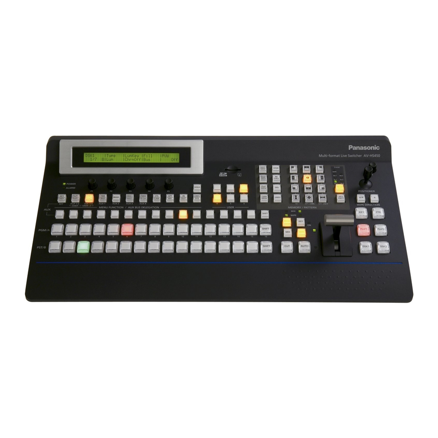
Page 20: Functions In Each Area
2. Functions in each area 2-1. Control panel User button area Wipe pattern/memory area LCD menu area SD memory card area Positioner area Multi-format Live Switcher AV-HS450 PAGE SHOT STOR WIPE BKGD WIPE CALL POWER ALARM PinP BKGD HOLD PATT POSITIONER ... -
Page 21: Crosspoint Area
2. Functions in each area Crosspoint area 2-1-1. PinP1 DSK1 TIME IMAGE A FMEM CONFIG BKGD CKEY PinP2 DSK2 CBGD IMAGE B SDCard PinP 1/2 DSK 1/2 AUX1 AUX2 AUX3 AUX4 AMBER:1 / GREEN :2 MENU FUNCTION / AUX BUS DELEGATION USER ... -
Page 22: Wipe Pattern/Memory Area
2. Functions in each area AUX bus crosspoint buttons These buttons are used to select the source of the bus which was selected by the AUX bus selector button (). Buttons 1 to 32 can be selected using the [SHIFT] button. ... -
Page 23: User Button Area
2. Functions in each area 2-1-3. User button area User buttons [USER1 to USER6] These are used to assign some functions of the menu settings to the [USER1] to [USER6] buttons on the CONFIG menu. See “5-3-1. Setting the user buttons”. USER 2-1-4. - Page 24 2. Functions in each area [MIX] button This is used to switch the A and B bus images while making them overlap. During the transition, the A and B bus output total is kept at 100 %. When the [MIX] button is pressed and it is selected, its indicator lights in amber. If the [WIPE] button () is now pressed, it goes off, and the de-selected status is established.
- Page 25 2. Functions in each area Wipe direction selection buttons [WIPE DIRECTION N/R, R] These buttons are used to select the direction in which to wipe for executing background transitions. When the [R] indicator is off: Wiping proceeds in the normal direction. When the [R] indicator is lit: Wiping proceeds in the reverse direction.
-
Page 26: Lcd Menu Area
2. Functions in each area 2-1-5. LCD menu area POWER ALARM HOLD PinP1 DSK1 TIME IMAGE A FMEM CONFIG BKGD CKEY PinP2 DSK2 CBGD IMAGE B SDCard PinP 1/2 DSK 1/2 AUX1 AUX2 AUX3 AUX4 AMBER:1 / GREEN :2 MENU FUNCTION / AUX BUS DELEGATION ... - Page 27 2. Functions in each area Menu function buttons [MENU FUNCTION/AUX BUS DELEGATION] These are used to select the menus organized by function. Each time one of these buttons is pressed, the menu for its function is switched between the one displayed above and the one displayed below.
-
Page 28: Positioner Area
2. Functions in each area Positioner area 2-1-6. Positioner [X/Y] These are used when performing the settings below. PinP1, PinP2 position settings Wipe start position setting (WIPE No.5, WIPE No.11, SQ No.5) Camera control ... -
Page 29: Sd Memory Card Area
Doing so can damage the data on the SD memory card. Concerning the recommended SD memory cards and SDHC memory cards Use of the following SD memory cards and SDHC memory cards made by Panasonic is recommended: SDHC memory cards RP-SDM04G, RP-SDM06G, RP-SDM08G,... -
Page 30: Rear Panel Connections Area
2. Functions in each area 2-1-8. Rear panel connections area LCD CONTRAST SERVICE NORMAL TALLY / GPI MAINFRAME 12V IN 1 12V IN 2 POWER SIGNAL TALLY/GPI input/output connector [TALLY/GPI] (D-sub 25-pin, female, inch screw) ... -
Page 31: Mainframe
2. Functions in each area 2-2. Mainframe 2-2-1. Front panel Power supply 1 Power supply 2 POWER1 POWER2 POWER1 POWER2 ALARM1 ALARM2 Multi-format Live Switcher AV-HS450 Power switch [POWER1, POWER2] These are used to turn the power on and off. As a standard feature, this mainframe has a redundant power supply system. -
Page 32: Rear Panel Connections Area
2. Functions in each area 2-2-2. Rear panel connections area SLOT A SLOT B IN/OUT A1 IN/OUT A2 IN/OUT B1 IN/OUT B2 SDI INPUTS SIGNAL EDITOR SDI OUTPUTS DVI-D OUTPUTS TALLY/GPI PANEL ... - Page 33 2. Functions in each area LAN connector [LAN] (RJ-45) (10/100 Base-TX) For details on how to connect this connector, refer to “6. External interfaces”. EDITOR connector [EDITOR] (RS-422, D-sub 9-pin, female, inch screw) COM connector [COM] (RS-422, D-sub 9-pin, female, inch screw) ...
-
Page 34: Basic Operations
3. Basic operations 3-1. Background transition 3-1-1. Selecting the bus Press one of the crosspoint buttons to select the material to be used for the background transition. Depending on the operating status, the button pressed will light in one of two colours. Lighting in red: When the selected input signals are output to PGM. - Page 35 3. Basic operations All SHIFT All SHIFT is used to switch all the materials of the PGM/A bus crosspoint buttons, PST/B bus crosspoint buttons or AUX bus crosspoint buttons from front materials to rear materials or vice versa. The USER button to which the SHIFT function has been allocated is used to switch between the front materials and rear materials.
- Page 36 3. Basic operations Turn [F4] to select the button to which the SHIFT function is to be allocated using the Shift item. Right: Button No.16 Left: Button No.1 Off: Function is not allocated. Turn [F5] to select the operation to be performed when the [SHIFT] button is pressed using the Sf-Lock item. Off: The rear material is selected only while the [SHIFT] button is pressed.
-
Page 37: Selecting The Bus Mode
3. Basic operations 3-1-3. Selecting the bus mode Select the A/B bus system or flip-flop system (PGM/PST system) from the setting menu. Press the [CONFIG] button to light its indicator, and display the CONFIG menu. Refer to “2-1-5. LCD menu area”. ... -
Page 38: Selecting The Transition Mode
3. Basic operations 3-1-4. Selecting the transition mode Press the [BKGD] button in the transition area so that its indicator lights in amber. When the [BKGD] button and [KEY] button are pressed at the same time, both buttons are selected. Use the [MIX] and [WIPE] buttons in the transition area to select the background transition mode. -
Page 39: Image
3. Basic operations 3-2. IMAGE 3-2-1. Setting the IMAGE effects Four effects — paint, mono-colour, mosaic and defocus — can be set for the PGM/A bus materials and PST/B bus materials. Press the [IMAGE A] button (or the [IMAGE B] button) to light its indicator, and display the IMAG A (or IMAG B) menu. -
Page 40: Executing The Image Effect
3. Basic operations 3-2-2. Executing the IMAGE effect While the IMAGE effect is set to On, the crosspoint button with the bus material to which the IMAGE effect has been added now blinks. The IMAGE effects are created as DVEs (digital video effects) so their output is delayed by one frame from the normal output. -
Page 41: Wipe
3. Basic operations 3-3. Wipe PAGE WIPE 3-3-1. Selecting the wipe pattern Based on the wipe patterns allocated to 12 buttons, this unit has 7 pages of background transition patterns and 4 pages of key transition patterns. (Refer to “Table of wipe patterns”.) BKGD PATT The images and number of the basic wipe patterns are displayed on the... - Page 42 3. Basic operations Background transition pattern pages WIPE SQ1 (squeeze 1) SL1 (slide 1) 3D1 (3 dimensions 1) pattern pattern pattern pattern pattern SQ2 (squeeze 2) SL2 (slide 2) 3D2 (3 dimensions 2) pattern pattern pattern pattern pattern pattern pattern pattern pattern...
-
Page 43: Selecting The Background For The 3D2 Pattern Page
3. Basic operations 3-3-2. Selecting the background for the 3D2 pattern page On the 3D2 (3 dimensions 2) pattern page, a still image in one of the frame memories (FMEM1 to 4), colour background (CBGD) or Black can be selected for the background. ... -
Page 44: Wipe Decorations (Border, Soft Effect)
3. Basic operations 3-3-4. Wipe decorations (border, soft effect) A border effect or soft effect can be added to the wiping of background transitions. Setting the border and soft effect Press the [BKGD] button to light its indicator, and display the BKGD menu. ... -
Page 45: Setting The Wipe Start Position
3. Basic operations 3-3-5. Setting the wipe start position Any start position can be set for WIPE patterns No.5 and No.11 and for SQ pattern No.5 among the wipe patterns. For WIPE patterns No.5 and No.11, the position is set using the WIPEPos sub menu of the BKGD menu. For SQ pattern No.5, it is set using the SQPos sub menu of the BKGD menu. -
Page 46: Modifying Wipe
3. Basic operations 3-3-6. Modifying wipe Setting the lighting effect Lighting effects can be added when the following wipe patterns have been selected: 3D1 page: No.1, No.3, No.7, No.9 These effects can be set for background transitions and key transitions. ... - Page 47 3. Basic operations Setting the trimming When SQ1, SQ2, SL1, SL2, 3D1 or 3D2 has been selected as the wipe pattern, the trimming at the time a background transition is executed can be set. The “4:3” and “4:3Smth” settings for the Trim item take effect when the HD format has been selected as the system format setting.
-
Page 48: Key
3. Basic operations 3-4. Key This operation combines the background image with another image. The key definition can be adjusted, and an edge can be added to the combined image. Also available as materials besides KEY for combining with the background image are PinP (picture in picture) and DSK (downstream key). -
Page 49: Selecting The Key Type
3. Basic operations 3-4-1. Selecting the key type Press the [KEY] button to light its indicator, and display the KEY menu. Refer to “2-1-5. LCD menu area”. Turn [F1] to display the KEY sub menu. Turn [F2] to select the Type item. <Menu display>... -
Page 50: Selecting The Key Material
3. Basic operations 3-4-2. Selecting the key material Selecting the key fill signal Press the [KEY] button among the AUX bus selector buttons to light its indicator, and press one of the AUX bus crosspoint buttons (1 to 32) to select the key fill signal. Selecting the key source signal Set the key source for key fill. -
Page 51: Key Transitions
3. Basic operations 3-4-3. Key transitions Select the transition mode. WIPE Press the [KEY] button in the transition area to light its indicator. To execute a background transition and key transition at the same BKGD time, press the [BKGD] button and [KEY] button together to turn on both indicators. -
Page 52: Key Preview
3. Basic operations Execute the transition. Press the [AUTO] button in the transition area to automatically execute the transition at the transition time that has been set. Alternatively, execute the transition manually by operating the fader lever. Key auto transition When the [KEY ON] button in the transition area is pressed, the transition is automatically executed at the transition time that has been set. -
Page 53: Adjusting The Luminance Key And Linear Key
3. Basic operations 3-4-5. Adjusting the luminance key and linear key These steps are taken to adjust the luminance key and linear key definition. Press the [KEY/CKEY] button to light its indicator, and display the KEY menu. Refer to “2-1-5. LCD menu area”. ... -
Page 54: Adjusting The Chroma Key
3. Basic operations 3-4-6. Adjusting the chroma key Sampling is executed for the selected key materials to adjust those aspects of the key that are to be compensated. Step 1 <Menu display> To execute the sampling automatically CHRKEY 1 | AutCmp↓ | | RESET↓... - Page 55 3. Basic operations Step 2 The objective of this step is to remove the noise in the background image. The noise is removed by carrying out this step several times. On the CHR KEY menu, turn [F1] to display the Sample1 sub menu. <Menu display>...
- Page 56 3. Basic operations Step 3 The objective of this step is to remove the noise in the foreground image. The noise is removed by carrying out this step several times. Turn [F2] to select “Matte” using the View item. <Menu display>...
- Page 57 3. Basic operations Step 4 After steps 1 to 3 have been carried out, noise will still remain in the detail areas such as the subject’s hair as shown in the image on the right. If there are many areas with noise, the noise is removed by carrying out this step several times.
- Page 58 3. Basic operations Step 5 The objective of this step is to finely adjust the image by adjusting the noise and transparency, for example. On the CHR KEY menu, turn [F1] to display the Sample2 sub menu. <Menu display> CHRKEY 3 | View | Mode | UNDO↓...
- Page 59 3. Basic operations [Spill–] [Spill+] In these modes, the noise in the foreground image can be removed or restored step by step through repeated sampling. Spill [–] [Matte–] [Matte+] In these modes, the matte information is adjusted. If, for instance, the area of shadow in the foreground image is to be made lighter, use [Matte−] to adjust. Conversely, to make it darker, use [Matte+].
- Page 60 3. Basic operations [Detail–] [Detail+] In these modes, the noise in the background image can be removed step by step. This is a useful way of adjusting images lost by other sampling operations to adjust the texture or transparency of images. [–] Detail [MatSpng]...
- Page 61 3. Basic operations [FineTun] In this mode, detailed images can be adjusted. On the CHR KEY menu, turn [F1] to display the FineTun sub menu. <Menu display> CHRKEY 4 | View | Spill | Trans | Detail FineTun | Cmpsit| ...
-
Page 62: Key Decorations
3. Basic operations 3-4-7. Key decorations A border, shadow or other edge can be added to the key. Setting the key edge Press the [KEY] button to light its indicator and <Menu display> 4 | Type | Width | Direc display the KEY menu. -
Page 63: Masking The Key Signals
3. Basic operations 3-4-8. Masking the key signals These steps are taken to mask the key signals using the mask signal of the box pattern. Press the [KEY] button to light its indicator and display the KEY menu. Refer to “2-1-5. LCD menu area”. ... -
Page 64: Flying Key
3. Basic operations 3-4-9. Flying key Using DVE effects, this key enables the key signals that have been input to be moved, expanded or contracted. In order for the flying key to take effect, select SL No.5 as the key transition. When the key transition is executed, the keys are combined by the key signals set using the flying key menu. -
Page 65: Pinp (Picture In Picture)
3. Basic operations 3-5. PinP (picture in picture) Another image can be combined with the background image. This unit supports two PinP channels. 3-5-1. Selecting the PinP channel and material Press the [PinP 1/2] button among the AUX bus selector buttons. When the button is lit in amber, the PinP1 sub menu is displayed on the LCD, and the state in which the PinP1 materials are selected is now established for the AUX bus crosspoint buttons. -
Page 66: Selecting Shape
3. Basic operations 3-5-2. Selecting Shape Square or Circle can be selected as the shape used for combining PinP1 images. PinP2 images are fixed as Square. Press the [PinP1/PinP2] button to light its indicator and display the PinP1 menu. ... -
Page 67: Pinp Transitions
3. Basic operations 3-5-4. PinP transitions Set the transition time. On the TIME menu, turn [F1] to display the PinP1 sub menu (or PinP2 sub menu). As with background transitions, set the transition time. Refer to “3-1-6. Auto transition”. ... - Page 68 3. Basic operations Adjusting the rotation angle On the PinP1 menu (or PinP2 menu), turn [F1] to display the Rotation sub menu. Either operate the positioner and rotary encoder [Z] or turn [F2], [F3] and [F4] to set the X rotation, Y rotation and Z rotation.
-
Page 69: Linking Pinp1 And Pinp2
3. Basic operations 3-5-6. Linking PinP1 and PinP2 The PinP1 and PinP2 images perform a symmetrical operation for the axis whose coordinates and rotation angle have been set. The image serving as the reference is the PinP image of the menu being operated. ... -
Page 70: Pinp Decorations
3. Basic operations 3-5-7. PinP decorations A border or soft effect can be added to PinP. Press the [PinP1] button (or [PinP2] button) to light its indicator and display the PinP1 menu (or PinP2 menu). Refer to “2-1-5. LCD menu area”. ... -
Page 71: Trimming Settings
3. Basic operations 3-5-8. Trimming settings Press the [PinP1] button (or [PinP2] button) to light its indicator and display the PinP1 menu (or PinP2 menu). Refer to “2-1-5. LCD menu area”. Turn [F1] to display the Trim sub menu. <Menu display>... -
Page 72: Dsk (Downstream Key)
3. Basic operations 3-6. DSK (downstream key) Characters or other images can be combined with the background image. This unit supports two DSK channels. 3-6-1. Selecting the DSK type Press the [DSK1] button (or [DSK2] button) to light its indicator and display the DSK1 menu (or DSK2 menu). - Page 73 3. Basic operations Setting the fill matte colour On the DSK1 menu (or DSK2 menu), turn [F1] to display the FillMatt sub menu. <Menu display> 3 | Hue | Sat | Lum | Load↓ DSK1 FillMatt| 0.0| 0.0| 100.0| White Yellow Cyan...
-
Page 74: Selecting The Dsk Channel And Dsk Fill Material
3. Basic operations 3-6-2. Selecting the DSK channel and DSK fill material When the [DSK 1/2] button among the AUX bus selector buttons is pressed and it has lit in amber, DSK1 is displayed as the menu. The state in which the DSK1 fill material is selected is now established for the AUX bus crosspoint buttons. If the button has lit in green, DSK2 is displayed as the menu, and the state in which the DSK2 fill material is selected is now established for the AUX bus crosspoint buttons. -
Page 75: Dsk Transitions
3. Basic operations 3-6-3. DSK transitions Set the transition time. On the TIME menu, turn [F1] to display the DSK1 sub menu (or DSK2 sub menu). As with background transitions, set the transition time. Refer to “3-1-6. Auto transition”. ... -
Page 76: Dsk Adjustments
3. Basic operations 3-6-5. DSK adjustments The DSK definition can be adjusted. Press the [DSK1] button (or [DSK2] button) to light its indicator and display the DSK1 menu (or DSK2 menu). Refer to “2-1-5. LCD menu area”. Turn [F1] to display the Adjust sub menu. <Menu display>... -
Page 77: Dsk Decorations
3. Basic operations 3-6-6. DSK decorations A border, shadow or other type of edge can be added to DSK. Setting the edge <Menu display> Press the [DSK1] button (or [DSK2] button) to light 4 | Type | Width | Direc DSK1 its indicator and display the DSK1 menu (or DSK2 Edge... -
Page 78: Masking The Dsk Signals
3. Basic operations 3-6-7. Masking the DSK signals These steps are taken to mask the DSK signals using the mask signal of the box pattern. Press the [DSK1] button (or [DSK2] button) to light its indicator and display the DSK1 menu (or DSK2 menu). -
Page 79: Ftb (Fade To Black)
3. Basic operations 3-7. FTB (fade to black) The user can fade out from a programme image to the black screen or fade in to a programme image from a black screen. Set the duration of the transition. On the TIME menu, turn [F1] to display the FTB sub menu. As with a background transition, set the transition time. -
Page 80: Internal Colour Signals
3. Basic operations 3-8. Internal colour signals 3-8-1. Setting the colour background The colour background to be used by the bus can be set. Two methods are available: under one method the Hue (hue), Sat (colour saturation) and Lum (luminance) are set, and under the other the 8 preset colours (white, yellow, cyan, green, magenta, red, blue and black) are called. -
Page 81: Switching The Aux Output
3. Basic operations 3-9. Switching the AUX output 3-9-1. Selecting the AUX output materials The AUX1 to AUX4 output signals can be selected. Press one of the [AUX1] to [AUX4] buttons among the AUX bus selector buttons. The selected button lights in amber. ... -
Page 82: Aux1 Transitions
3. Basic operations 3-9-2. AUX1 transitions The MIX transition is executed when the output signal set for AUX1 is switched. Press the [AUX1] button of the AUX bus selector buttons. The selected button and its corresponding AUX bus crosspoint button light in amber. ... -
Page 83: Setting Enable/Disable For The Aux1 Transition
3. Basic operations 3-9-3. Setting enable/disable for the AUX1 transition The AUX1 transition time and transition enable/disable can be set. Press the [TIME] button to light its indicator and display the TIME menu. Refer to “2-1-5. LCD menu area”. ... -
Page 84: Memory
3. Basic operations 3-10. Memory Background transition patterns, PinP sizes, border widths and other video statuses can be stored in and recalled from the memory. Depending on what statuses are to be stored in the memory, the SHOT memory, BKGD/WIPE memory, PinP memory and CAM memory are available. -
Page 85: Memory Registration And Recall Items
3. Basic operations 3-10-1. Memory registration and recall items Material selected Transition Pattern Menu PGM/A bus Fader amount BKGD patterns KEY SHOT memory PST/B bus CHR KEY [SHOT MEM] (BKGD, KEY) (MIX, WIPE) PinP1 bus ... -
Page 86: Storing The Settings In The Memory (Store)
3. Basic operations 3-10-2. Storing the settings in the memory (Store) The settings for the images and operations to be kept in the memory can be stored in the number keys (1 to 10). PAGE SHOT STOR WIPE BKGD WIPE CALL PinP BKGD... -
Page 87: Recalling The Operations Stored In The Memory (Recall)
3. Basic operations 3-10-3. Recalling the operations stored in the memory (Recall) Recall PAGE SHOT STOR WIPE BKGD WIPE CALL PinP BKGD PATT UNDO PATT XPT DSBL EFF DSLV MEMORY / PATTERN Press one of the buttons — [SHOT MEM], [BKGD WIPE MEM], [PinP MEM] or [CAM MEM] — to select the corresponding memory whose operations are to be recalled. -
Page 88: Deleting The Operations Stored In The Memory (Delete)
3. Basic operations 3-10-4. Deleting the operations stored in the memory (Delete) PAGE SHOT STOR WIPE BKGD WIPE CALL PinP BKGD PATT UNDO PATT XPT DSBL EFF DSLV MEMORY / PATTERN Press one of the buttons — [SHOT MEM], [BKGD WIPE MEM], [PinP MEM] or [CAM MEM] — to select the corresponding memory whose operations are to be deleted. -
Page 89: Effect Dissolve
3. Basic operations 3-10-5. Effect dissolve Switching from the current image to the image or operation stored in the SHOT memory can be performed smoothly. For the items targeted by effect dissolve, refer to the SHOT memory items in “3-10-1. Memory registration and recall items”. -
Page 90: Frame Memories
3. Basic operations 3-11. Frame memories Still images can be stored in the unit’s four internal frame memories for use. The still images are transferred to the frame memories through the AUX bus and an SD memory card. Conversely, the images in the frame memories can be transferred to an SD memory card. Images in the frame memories can be used as bus images by assigning FMEM1 to FMEM4 using the crosspoint assignment function. -
Page 91: Saving Images In Flash Memory
3. Basic operations 3-11-2. Saving Images in Flash Memory Data for images stored in the frame memory can be retained even when the power is turned off, by saving them in the flash memory area built into the mainframe. Whether to automatically save the image data stored in the frame memory when the data is transferred from the AUX bus or to manually save them must be set. -
Page 92: Sd Memory Cards
3. Basic operations 3-12. SD memory cards The unit’s frame memory data and setup data can be stored on SD memory cards. Conversely, this data can be loaded from the SD memory cards to the unit. Frame memory data (still image data): The unit supports 24-bit (uncompressed) BMP (bitmap) and JPEG (baseline) is the only file formats. -
Page 93: Initializing The Sd Memory Cards
3. Basic operations 3-12-1. Initializing the SD memory cards In order for an SD memory card to be used in the unit, it must first be initialized by the unit. Initializing the SD memory card formats it (in compliance with the SD standard) and creates the dedicated directory. (All files saved on the SD memory card will be erased.) ... -
Page 94: Saving Data On Sd Memory Cards
3. Basic operations 3-12-2. Saving data on SD memory cards Insert the SD memory card which has been initialized by the unit, into the SD memory card slot. Press the [SDCard] button to light its indicator and display the SDCard menu. ... -
Page 95: Loading Data From Sd Memory Cards
3. Basic operations 3-12-3. Loading data from SD memory cards Insert the SD memory card on which the data is stored into the SD memory card slot. Load the file after its data has been stored in the each folder. Data stored in other folders will not be recognized by the unit. -
Page 96: Deleting Files On Sd Memory Cards
3. Basic operations 3-12-4. Deleting files on SD memory cards Insert the SD memory card on which the data is stored into the SD memory card slot. On the SDCard menu, turn [F1] to display the File sub menu. ... -
Page 97: Input/Output Signal Settings
4. Input/output signal settings 4-1. Input signal settings IN1 to IN16 are SDI signal inputs. IN A1, IN A2, IN B1 and IN B2 can be set only when one of the following option boards has been connected. AV-HS04M1 (SDI Input Board) ... -
Page 98: Setting The Frame Synchronizer
4. Input/output signal settings 4-1-1. Setting the frame synchronizer The frame synchronizer can be set to On or Off for each input. The DVI input (option) frame synchronizer is permanently On. It cannot be set from On to Off or vice versa. ... -
Page 99: Setting The Input Mode
4. Input/output signal settings 4-1-2. Setting the input mode The mode can be set for each input only when HD has been selected as the system format. When SD is selected as the system format, the input mode is always the same as Normal. Normal: Input signals in conformity with the system format take effect. -
Page 100: Freezing The Input Signals
4. Input/output signal settings Freezing the input signals 4-1-3. The input signals can be frozen and used. While signals are frozen, the tally signals of the corresponding input will not be output. Setting freeze Press the [INPUT] button to light its indicator and display the INPUT menu. ... -
Page 101: Colour Corrector
4. Input/output signal settings 4-1-4. Colour corrector When the colour corrector is enabled, the colours of the input video signals can be corrected. This function can be set for the signals that are input to IN9 to IN16. Enabling the colour corrector ... - Page 102 4. Input/output signal settings Process control Adjusting the Y signal gain and setting its pedestal level (black level) On the INPUT XX sub menu, turn [F2] to display the third menu of CC Prc1. <Menu display> INPUT XX | CC Prc1 | Y-Gain | Ped 7/15 | 100.0| 0.0|...
- Page 103 4. Input/output signal settings Tone curve The gray scale of the input images can be compensated. Set the tone curve, and adjust the image brightness, contrast GPos and other characteristics. By adjusting each of the R, G and B colours separately, the white balance and colour tone can be adjusted.
- Page 104 4. Input/output signal settings Adjusting the colour matrix item gain On the INPUT XX sub menu, turn [F2] to display the third menu of CC MTX1. <Menu display> INPUT XX | CC MTX1 | R-G | R-B | 13/15 | 0.000| 0.000| −0.600...
-
Page 105: Setting The Up-Converter
4. Input/output signal settings Setting the up-converter 4-1-5. Select the settings for INPUT13 to 16, as well as for the up-converter that is built into the option boards listed below: AV-HS04M1 (SDI Input Board) AV-HS04M2 (Analogue Input Board) ... -
Page 106: Setting The Analogue Input Gain (Option)
4. Input/output signal settings Fine-tuning of image positions Fine-tuning of image positions is performed when EC (edge crop) is selected for the scaling method. On the INPUT XX sub menu, turn [F2] to display the third menu of UpConv2. <Menu display>... -
Page 107: Setting The Analogue Composite Input Signals (Option)
4. Input/output signal settings 4-1-7. Setting the analogue composite input signals (option) When the analogue composite input board (option) has been connected, the analogue composite input signals can be set. Press the [INPUT] button to light its indicator and display the INPUT menu. ... -
Page 108: Setting The Dvi Input Signals (Option)
4. Input/output signal settings 4-2. Setting the DVI input signals (option) 4-2-1. Setting the DVI input signals Set the DVI input signals when the DVI input board (option) or full HD DVI input board (option) has been connected. Signals with the following resolutions can be input. If signals with any other resolution or frequency are input, the picture will turn black. - Page 109 4. Input/output signal settings Turn [F4] to select the scaling method. Fit-V: The aspect ratio of the input images is maintained, and the size of the images is increased or reduced in accordance with the vertical resolution. Fit-H: The aspect ratio of the input images is maintained, and the size of the images is increased or reduced in accordance with the horizontal resolution.
- Page 110 4. Input/output signal settings DVI input scaling size table HD/1080i HD/720P SD/NTSC SD/PAL DVI format Mode 1920 1080 1280 720 720 480 720 576 Fit-V 1024768 Fit-H FULL SXGA Fit-V 12801024 Fit-H FULL WXGA Fit-V 1280768 Fit-H FULL...
- Page 111 4. Input/output signal settings HD/1080i HD/720P SD/NTSC SD/PAL DVI format Mode 1920 1080 1280 720 720 480 720 576 1728 WSXGA+ Fit-V 1152 16801050 1080 Fit-H 1920 FULL 1280 1080 UXGA Fit-V 1440 16001200 1080 Fit-H 1920 FULL 1280...
-
Page 112: Adjusting The Dvi Input Signals
4. Input/output signal settings 4-2-2. Adjusting the DVI input signals Adjust the clock/phase and position of the DVI-I input signals. Press the [INPUT] button to light its indicator and display the INPUT menu. Refer to “2-1-5. LCD menu area”. ... -
Page 113: Setting The Output Signals
4. Input/output signal settings 4-3. Setting the output signals OUT1 to OUT4 are SDI signal outputs. OUT5 and OUT6 are DVI-D signal outputs. OUT A1, OUT A2, OUT B1 and OUT B2 can be set only when one of the following option boards has been connected. -
Page 114: Assigning The Output Signals
4. Input/output signal settings 4-3-1. Assigning the output signals Assign the output signals to OUTPUT1 to OUTPUT10. Press the [OUTPUT] button to light its indicator and display the OUTPUT menu. Refer to “2-1-5. LCD menu area”. Turn [F1] to display the OUTPUTYY sub menu. (Y: OUT1 to OUT6, A1, A2, B1 or B2) The output used to assign the output signal is selected for Y. - Page 115 4. Input/output signal settings When the SDI output board (option) has been connected, turn [F4] to set the output mode using the Mode item, and press the [F4] switch to enter the setting. An asterisk () appears on the left of the currently selected output mode. Normal: The same signals as the system format signals are output.
-
Page 116: Setting The Dvi Output Signals (Out5 And Out6 Standard Outputs And Options)
4. Input/output signal settings 4-4. Setting the DVI output signals (OUT5 and OUT6 standard outputs and options) Set the DVI output signals of the OUT5 and OUT6 standard outputs and the DVI output signals if the DVI/analogue output board (option) has been connected. ... - Page 117 4. Input/output signal settings Turn [F5] to select the scaling method, and press the [F5] switch to enter the selection. Fit-V: The aspect ratio of the output images is maintained, and the size of the images is increased or reduced in accordance with the vertical resolution.
-
Page 118: Setting The Down-Converter (Option)
4. Input/output signal settings 4-5. Setting the down-converter (option) Select the settings for the down-converter that is built into the SDI output board (option). <Menu display> Press the [OUTPUT] button to light its indicator OUTPUTYY | DownCnv | Scale↓ | Delay↓ | Sharp↓ and display the OUTPUT menu. -
Page 119: Setting The Sync Signals
4. Input/output signal settings 4-6. Setting the sync signals The sync signals to be used by the system can be selected. External sync: For synchronization with an external sync signal (gen-lock). The reference input signal is looped through and output. BBST: Black burst signal (vertical phase of 0H) BBAD: Black burst signal Vertical phase of 90H when the 59.94i or 59.94p format is selected;... -
Page 120: Adjusting The Output Signal Phase
4. Input/output signal settings 4-7. Adjusting the output signal phase The phase of the output video signals can be adjusted. Press the [SYSTEM] button to light its indicator and display the SYSTEM menu. Refer to “2-1-5. LCD menu area”. ... - Page 121 4. Input/output signal settings <Phase adjustment setup> (System standard) Approx. 0.2H AVDL Range Approx. –0.2H to +0.8H Internal Approx. Fixed DL 0.2H • 1H Output (+1H) Output Phase Variable Range H Phase (–0.5H to +0.5H) + V Phase (±100 lines) AVDL Range Internal Approx.
- Page 122 4. Input/output signal settings <Phases and delay amounts of input/output signals during HD format use> Frame synchronizer Output On, Off signals Mode: Input Normal, UC or Video effects signals DbyD (cannot be selected when the system format is 720p) (Down-converter) ...
- Page 123 4. Input/output signal settings <Phase relationship between input signals and output signals> (for 1080/59.94i format) (Example 1) Input signals (non-synchronized) Sync signal (Ref) 1F (frame) Output signal Max. 1F Output signal (90H) Max. 1F+90H Output signal (1F) Max.
-
Page 124: Setting The Multi View Display
4. Input/output signal settings 4-8. Setting the multi view display The input images, programme images, preview images, etc. can be arranged on the screen of an external monitor and output to two lines (MV1 and MV2). 4-8-1. Setting the screen layout There are four multi view split-screen display modes: 16 split (the main screen is split into 16 subscreens), 10 split, 9 split and 4 split. - Page 125 4. Input/output signal settings Press the [MV] button to light its indicator and display the MV menu. Refer to “2-1-5. LCD menu area”. Turn [F1] to select the MV1 PATT or MV2 PATT sub menu depending on the multi view output signals to be set.
-
Page 126: Setting The Split Frame And Characters
4. Input/output signal settings 4-8-2. Setting the split frame and characters Set the frame, character brightness and background of the split screens to be displayed on the multi view display. Press the [MV] button to light its indicator and display the MV menu. ... -
Page 127: Setting The Tally Displays
4. Input/output signal settings 4-8-3. Setting the tally displays Set the tally displays to be superimposed onto the split frame of the multi view display. The red tally indicates material consisting of programme outputs. The green tally indicates material selected by the preset bus. On the MV1Frame or MV2Frame sub menu, turn [F5] to set the tally displays using the Tally item. -
Page 128: Changing The Material Names
4. Input/output signal settings 4-8-4. Changing the material names Change the names of the INPUT 1 to INPUT 16, INPUT A1, INPUT A2, INPUT B1 and INPUT B2 materials that are to be set on the multi view display. The default settings, preset settings or user settings can be selected for these names. When the preset settings and user settings are established, the material name (CAM1, etc.) display format is used. -
Page 129: High-Resolution Multi View Mode
4. Input/output signal settings 4-8-5. High-resolution multi view mode When the system mode is set to SD, the DVI-D output can be output in high resolution. If this is the case, MV1 is set for OUT5, and MV2 for OUT6. MV1 and MV2 cannot be set for any other outputs. -
Page 130: Setting The On-Screen Display (Osd)
4. Input/output signal settings 4-9. Setting the on-screen display (OSD) The menu screen can be superimposed onto the preview output or multi view display 1 or 2 output for display. <Menu display> Press the [CONFIG] button to light its indicator and CONFIG10 | OSD | Select | display the CONFIG menu. -
Page 131: Setting The Ancillary Data
4. Input/output signal settings 4-10. Setting the ancillary data In this section, the function for allowing the ancillary data of the SDI input signals to pass through is set. If SD format signals are input while the HD format has been set as the system format, it will not be possible for their ancillary data to be passed through. -
Page 132: System Settings
5. System settings 5-1. Setting the video format One system (input/output signal) video format can be selected. Press the [SYSTEM] button to light its indicator and display the SYSTEM menu. Refer to “2-1-5. LCD menu area”. Turn [F1] to display the Format sub menu. <Menu display>... -
Page 133: Setting The Crosspoints
5. System settings 5-2. Setting the crosspoints 5-2-1. Assigning signals to the crosspoints External video input signals and internally generated signals can be assigned to crosspoint buttons 1 to 32. Displaying the assignment statuses Press the [XPT] button to light its indicator and display the XPT menu. ... - Page 134 5. System settings The table below lists the materials which can be assigned. Button Signal Description XPT1 to 32 IN1 to IN16 SDI input 1 to 16 IN-A1, IN-A2, Option slot IN-B1, IN-B2 (SDI, analogue component, analogue composite and DVI) Black Internally generated signal, black CBGD...
-
Page 135: Setting The Crosspoint Switching
5. System settings 5-2-2. Setting the crosspoint switching The timing at which the crosspoints are to be switched can be set. Press the [XPT] button to light its indicator and display the XPT menu. Refer to “2-1-5. LCD menu area”. ... -
Page 136: Button Assignments
5. System settings 5-3. Button assignments 5-3-1. Setting the user buttons The user can assign several functions which can be set using the menu items into six user buttons (USER 1 to USER 6). The user buttons light in amber when the assigned function is ON and are off when the assigned function is OFF. Each time the user button is pressed, the function setting alternates between ON and OFF. - Page 137 5. System settings <Setting method> Press the [CONFIG] button to light its indicator and display the CONFIG menu. Refer to “2-1-5. LCD menu area”. Turn [F1] to display the Button1 sub menu and Button2 sub menu. <Menu display> CONFIG 8 | USER1 | USER2 | USER3...
-
Page 138: Setting The Date And Time
5. System settings 5-4. Setting the date and time The user can set the date and time to be used as the SD memory card’s time stamp. Be absolutely sure to set them when an SD memory card is to be used. Setting the date ... -
Page 139: Network Settings
5. System settings 5-5. Network settings Proceed with the network settings to perform such tasks as updating the software version via LAN. The network initial setup is: IP address: 192.168.0.10, subnet mask: 255.255.255.0. When using the host computer with settings matching the network setup, it is not necessary to setup via the menu. -
Page 140: Other Settings
5. System settings 5-6. Other settings Setting the LCD backlight The LCD backlight can be set to ON or OFF. It is also possible to automatically turn off the LCD backlight when no control panel operation is performed within a set time interval. -
Page 141: External Device Control
5. System settings 5-7. External device control 5-7-1. Enable/disable setting for control of external devices Set up the control of the external devices (editor, pan-tilt head and/or controller) that have been connected to the RS-422 (EDITOR, COM) connector. Press the [CTL] button to light its indicator and display the CTL menu. ... -
Page 142: Editor Control
(Compliant with the GVG protocol) • Read command • Crosspoint switch • Wipe pattern selection (BKGD) • Transition mode (MIX/WIPE) selection • Auto transition time setting • Auto transition execution <Table of wipe patterns supported> AV-HS450E AV-HS450E AV-HS450E AV-HS450E protocol protocol protocol protocol WIPE No.1... -
Page 143: Setting The Gpi
5. System settings 5-7-3. Setting the GPI The user can set the functions that are to be controlled from the GPI ports and set whether to enable the control. Refer to “6-2-4. TALLY/GPI” and “6-3-1. TALLY/GPI”. Press the [CONFIG] button to light its indicator and display the CONFIG menu. ... - Page 144 5. System settings Control using the GPI input port Assign Item Description of function assigned Control method AUTO AUTO button in transition area CUT button in transition area DSK1 DSK1 button in transition area DSK2 DSK2 button in transition area PinP1 PinP1 button in transition area Operations are performed using...
-
Page 145: Camera Control
5. System settings 5-7-4. Camera control A camera and pan-tilt head can be controlled from this unit. Up to five cameras can be controlled via a controller (AW-RP655L or AW-RP555L) connected to the unit’s COM connector. The unit can also be connected directly to a pan-tilt head, and the camera and pan-tilt head can be controlled. To control a camera in this way, select “P/TCont”... - Page 146 IN/OUT A2 IN/OUT B1 IN/OUT B2 SDI INPUTS SIGNAL EDITOR SDI OUTPUTS DVI-D OUTPUTS PANEL TALLY/GPI AV-HS450E AW-RP655L COM connector RS-422RS-232C converter Cable length: Max. 200 m Cable length: Max. 10 m Twisted pair cable (AWG24) <Connection specifications> AV-HS450E AW-RP655L RS-422RS-232C...
- Page 147 IN/OUT B2 ANALOG INPUTS SDI INPUTS SIGNAL EDITOR AW-HE100E SDI OUTPUTS DVI-D OUTPUTS PANEL TALLY/GPI AV-HS450E COM connector CONTROLLER connector Cable length: Max. 200 m Twisted pair cable (AWG24) <Connection specifications> AV-HS450E AW-HE100E, AW-PH405E, AW-PH360L Pin No. Signal Pin No.
- Page 148 IN/OUT B1 IN/OUT B2 SDI INPUTS SIGNAL EDITOR SDI OUTPUTS DVI-D OUTPUTS PANEL TALLY/GPI AV-HS450E AW-PH400E COM connector Cable length: Max. 200 m Cable length: Max. 500 m Twisted pair cable (AWG24) 10Base-T straight cable (UTP category 5) AW-IF400G Switch settings...
- Page 149 5. System settings Camera control settings Five cameras can be controlled either through the controller that is used for the camera (AW-RP555L or AW-RP655L) connected to the COM connector, or through the controller that is used for the pan-tilt head. ...
- Page 150 5. System settings Turn [F1] to display the CamCTL2 sub menu. <Menu display> 2 | CTL | PosCont | PTSpeed | Power↓ CamCTL2 | 1|PanTilt| Fast| 1-5 Zm/Focs Middle Slow Turn [F2] to set the camera to be controlled using the CTL item. ...
- Page 151 5. System settings Camera’s menu operations The camera’s menu displays, the movements of the cursor displayed on the menus and the entry of the changes made can be performed from the unit. Press the [CAM] button to light its indicator and display the CAM menu. ...
-
Page 152: Status Displays
5. System settings 5-8. Status displays 5-8-1. Alarm status displays The alert status (alarms) for this unit’s power supply and cooling fan are displayed on the LCD. Press the [SYSTEM] button to light it, and display the SYSTEM menu. ... -
Page 153: Displaying The Version Information And Option Information
5. System settings 5-8-3. Displaying the version information and option information Information on the unit’s software and hardware versions <Menu display> and the statuses of the options are displayed. 12 | Select | Version | | SysVer MainVer | MFSoft| 1.00| |1.00.00 ... -
Page 154: Initialization
5. System settings 5-9. Initialization 5-9-1. Initializing setting data Initialization returns the set data to the factory shipment status. (The network settings and the date and time settings are not initialized.) Press the [SYSTEM] button to light its indicator and display the SYSTEM menu. ... -
Page 155: External Interfaces
6. External interfaces 6-1. Connecting the control panel and mainframe Connect the MAINFRAME connector on the control panel and PANEL connector on the mainframe using the CAT5E cable supplied. CAT5E, straight cable, STP (shielded twisted pair), 10 m Provide the cable below if the control panel and mainframe are installed in a location where the CAT5E cable provided is not long enough to connect them (where the distance between the control panel and mainframe is more than 10 meters). -
Page 156: Editor
FRAME GROUND Frame ground 6-2-3. COM One or more Panasonic pan-tilt head systems can be controlled by the unit by connecting the system to the COM connector. For details on the connections, refer to “5-7-4. Camera control”. RS-422, D-sub 9-pin, female, inch screw Pin No. -
Page 157: Tally/Gpi
Dielectric strength: Max. DC 24 V 36 GPI In 6 Current: Max. 50 mA GPI In 7 GPI In 8 37 GPI Out Com AV-HS450E (Max. voltage: 24 V) GPI Out 1 GPI Out 2 38 GPI Out 3 GPI Out GPI Out 4... -
Page 158: Control Panel
Dielectric strength: Max. DC 24 V GPI In 6 Current: Max. 50 mA GPI In 7 GPI In 8 GPI Out Com AV-HS450E (Max. voltage: 24 V) GPI Out 1 GPI Out 2 GPI Out 3 GPI Out GPI Out 4... -
Page 159: Image Transmission Functions
7. Image transmission functions This unit comes with a function for transmitting still images from the host computer to the unit via LAN and a function for importing still images from the unit into the host computer. The image transmission software must be installed in the host computer from the CD-ROM supplied in order to use these functions. -
Page 160: How To Install The Software
7. Image transmission functions How to install the software This section describes how to install the image transmission software (HS450 Tool). Windows XP is used as the host computer’s operating system in the example given here. 1. Insert the CD-ROM supplied with the unit into the CD-ROM drive of the host computer in which the programme will be installed. - Page 161 7. Image transmission functions Operation This section describes how to operate the image transmission software (HS450 Tool). <Startup> On the Start menu of Windows, select [Programs] [Panasonic] [AV-HS450Tool] [HS450Tool]. The main screen now appears. <Exit> Click the [CLOSE] button.
- Page 162 7. Image transmission functions <Transmitting images to the unit> 1. Select the mode. Check that [To HS450]appears in the [Mode] field. If [From HS450] appears instead, click the [From HS450] button so that [To HS450] appears. 2. Select the transmission destination of the images in the [Target] field. FMEM1: Unit’s frame memory 1 FMEM2: Unit’s frame memory 2 FMEM3: Unit’s frame memory 3...
- Page 163 7. Image transmission functions <Transmitting images from the unit> 1. Select the mode. Check that [From HS450] appears in the [Mode] field. If [To HS450] appears instead, click the [To HS450] button so that [From HS450] appears. 2. Select the images to be imported to the host computer in the [Target] field. FMEM1: Images in unit’s frame memory 1 FMEM2: Images in unit’s frame memory 2 FMEM3: Images in unit’s frame memory 3...
-
Page 164: Setting Menu Table
8. Setting menu table A setting is entered when an item displayed (↓) is selected and then the [F1], [F2], [F3], [F4] or [F5] switch is pressed. (It will not be entered unless the switch is pressed.) Sub menu Parameter 1 Parameter 2 Parameter 3 Parameter 4... - Page 165 8. Setting menu table Sub menu Parameter 1 Parameter 2 Parameter 3 Parameter 4 Menu Turn F1 to select. Turn F2 to select. Turn F3 to select. Turn F4 to select. Turn F5 to select. KEY 11 Parameter Left Bottom Right MaskAdj Setting range...
- Page 166 8. Setting menu table Sub menu Parameter 1 Parameter 2 Parameter 3 Parameter 4 Menu Turn F1 to select. Turn F2 to select. Turn F3 to select. Turn F4 to select. Turn F5 to select. PinP1 PinP1 6 Parameter Trim Manual Trim Setting range...
- Page 167 8. Setting menu table Sub menu Parameter 1 Parameter 2 Parameter 3 Parameter 4 Menu Turn F1 to select. Turn F2 to select. Turn F3 to select. Turn F4 to select. Turn F5 to select. DSK1 DSK1 1 Parameter Type LumKey Fill DSK1...
- Page 168 8. Setting menu table Sub menu Parameter 1 Parameter 2 Parameter 3 Parameter 4 Menu Turn F1 to select. Turn F2 to select. Turn F3 to select. Turn F4 to select. Turn F5 to select. DSK2 DSK2 4 Parameter Type Width Direc Edge...
- Page 169 8. Setting menu table Sub menu Parameter 1 Parameter 2 Parameter 3 Parameter 4 Menu Turn F1 to select. Turn F2 to select. Turn F3 to select. Turn F4 to select. Turn F5 to select. TIME TIME 8 Parameter TransTime Unit EFF DSLV Setting range...
- Page 170 8. Setting menu table Sub menu Parameter 1 Parameter 2 Parameter 3 Parameter 4 Menu Turn F1 to select. Turn F2 to select. Turn F3 to select. Turn F4 to select. Turn F5 to select. IMAG A IMG A 1 Parameter On/Off IMAG A...
- Page 171 8. Setting menu table Parameter 1 Parameter 2 Parameter 3 Parameter 4 Sub menu Menu Turn F1 to select. Turn F2 to select. Turn F3 to select. Turn F4 to select. Turn F5 to select. Parameter Signal Tally Protcol CamCTL1 Setting range 1 to 5 IN1 to 16,...
- Page 172 8. Setting menu table Parameter 1 Parameter 2 Parameter 3 Parameter 4 Sub menu Menu Turn F1 to select. Turn F2 to select. Turn F3 to select. Turn F4 to select. Turn F5 to select. Parameter Split Signal MV1 PATT Setting range 16Split, 10Split, 1 to 16,...
- Page 173 8. Setting menu table Sub menu Third menu Parameter 1 Parameter 2 Parameter 3 Menu Turn F1 to select. Turn F2 to select. Turn F3 to select. Turn F4 to select. Turn F5 to select. Mode ↓ INPUT INPUT XX* Parameter (SDI) Normal, DbyD,...
- Page 174 8. Setting menu table Sub menu Third menu Parameter 1 Parameter 2 Parameter 3 Menu Turn F1 to select. Turn F2 to select. Turn F3 to select. Turn F4 to select. Turn F5 to select. Mode ↓ INPUT INPUT XX* Parameter AnaGain Normal, DbyD,...
- Page 175 8. Setting menu table Sub menu Third menu Parameter 1 Parameter 2 Parameter 3 Menu Turn F1 to select. Turn F2 to select. Turn F3 to select. Turn F4 to select. Turn F5 to select. Mode ↓ INPUT INPUT XX* Parameter AnaGain Normal, DbyD,...
- Page 176 8. Setting menu table Sub menu Third menu Parameter 1 Parameter 2 Parameter 3 Menu Turn F1 to select. Turn F2 to select. Turn F3 to select. Turn F4 to select. Turn F5 to select. Mode ↓ OUTPUT OUTPUTYY* Asign Parameter Source Normal, DC...
- Page 177 8. Setting menu table Parameter 1 Parameter 2 Parameter 3 Parameter 4 Sub menu Menu Turn F1 to select. Turn F2 to select. Turn F3 to select. Turn F4 to select. Turn F5 to select. CONFIG CONFIG 1 Parameter BusMode LCD-BL MENUDLG Operate...
- Page 178 8. Setting menu table Sub menu Parameter 1 Parameter 2 Parameter 3 Parameter 4 Menu Turn F1 to select. Turn F2 to select. Turn F3 to select. Turn F4 to select. Turn F5 to select. CONFIG CONFIG 6 Parameter Port Assign GPIEN GPIP-In...
- Page 179 8. Setting menu table Sub menu Parameter 1 Parameter 2 Parameter 3 Parameter 4 Menu Turn F1 to select. Turn F2 to select. Turn F3 to select. Turn F4 to select. Turn F5 to select. CONFIG CONFIG 8 Parameter USER1 USER2 USER3 Button1...
- Page 180 8. Setting menu table Sub menu Parameter 1 Parameter 2 Parameter 3 Parameter 4 Menu Turn F1 to select. Turn F2 to select. Turn F3 to select. Turn F4 to select. Turn F5 to select. SYSTEM (Message) Parameter The SYSTEM menu is locked. (When locked) Display only...
- Page 181 8. Setting menu table Sub menu Parameter 1 Parameter 2 Parameter 3 Parameter 4 Menu Turn F1 to select. Turn F2 to select. Turn F3 to select. Turn F4 to select. Turn F5 to select. SYSTEM SYS 12 Parameter Select Version SysVer (When...
-
Page 182: Appearance
9. Appearance Mainframe Unit: mm 76.2 Control panel Unit: mm Multi-format Live Switcher AV-HS450 PAGE SHOT STOR WIPE BKGD WIPE CALL POWER ALARM PinP BKGD HOLD PATT POSITIONER PinP1 DSK1 TIME IMAGE A FMEM CONFIG BKGD UNDO PATT CKEY PinP2 DSK2 CBGD IMAGE B... -
Page 183: Specifications
10. Specifications Mainframe [AV-HS450U1E] BNC 16 Video inputs Standard SDI: 16 signal lines (IN1 to IN16) (20 signal lines, Optional: Up to 4 additional signal lines (IN A1, IN A2, IN B1, IN B2) maximum) (Up to two option boards can be installed in the two input/output slots.) Standard SDI: 4 signal lines (OUT1 to OUT4 1 line each, BNC 5 Video outputs... - Page 184 10. Specifications SDI outputs HD: Serial digital component (SMPTE 292M) SD: Serial digital component (SMPTE 259M) 4 signal lines, standard: OUT1 2; OUT2, OUT3, OUT4 1 each 8 signal lines, maximum: OUT A1, OUT A2, OUT B1, OUT B2 (When two AV-HS04M7 boards are used) HD [SMPTE 292M (BTA S-004B) standard complied with] •...
- Page 185 10. Specifications DVI-D input Digital RGB: (option) XGA (1024768), WXGA (1280768), SXGA (12801024), WSXGA+ (16801050), UXGA (16001200), WUXGA (19201200) Vertical frequency: 60 Hz Digital RGB: 1080/50P, 1080/59.94P Analogue input signals are not supported. 4 signal lines, maximum: IN A1, IN A2, IN B1, IN B2 (When two AV-HS04M8 boards are used) ...
- Page 186 Used for maintenance purposes EDITOR RS-422 control connector D-sub, 9-pin, GVG standard protocol subset supported female RS-422 control connector D-sub, 9-pin, For Panasonic pan-tilt head system female control, etc. TALLY/GPI INPUT: D-sub, 50-pin, 8 inputs, general-purpose, photocoupler female...
- Page 187 10. Specifications Control panel [AV-HS450C1E] 100 Mbps 1 Control I/O MAINFRAME RJ45 For connecting the mainframe TALLY/GPI INPUT: 8 inputs D-sub, 25-pin, OUTPUT: 8 outputs female ALARM: 1 output External media SD memory cards Memory size supported: Max. 32 GB (SDHC memory cards supported) Still image files: Load, save Setup data: Backup...
-
Page 188: Appendix (Glossary)
Appendix (glossary) Defined below are the terms used in this manual. Word Explanation AB Bus system A bus control mode. By executing a transition, the A bus and B bus signals are output to the programme images alternately. Ancillary Data The auxiliary data other than the video signals which is transmitted inside the data stream of the video serial interface. - Page 189 Appendix (glossary) Word Explanation Frame Memory A memory which can hold the video signals equivalent to one frame. Frame Synchronizer A function which matches the synchronization of non-synchronized video input signals. Freeze A function which continues the display of the same image, creating the impression that the image has been “frozen”.
- Page 190 Appendix (glossary) Word Explanation The function for checking ahead of time the image which will be output after [Preview] the next transition. The image is output from the PVW system. The bus which always carries the programme output signals. [Programme Bus] The bus which carries the programme output signals after the next [Preset Bus] background transition.
- Page 191 Panasonic Corporation Web Site: ht t p:// pa na soni c. ne t Importer’s name & address to follow EU rules: Panasonic Testing Centre Panasonic Marketing Europe GmbH Winsbergring 15, 22525 Hamburg, F.R. Germany © Panasonic Corporation 2009 Printed in Japan...