Table of Contents
Advertisement
Available languages
Available languages
Quick Links
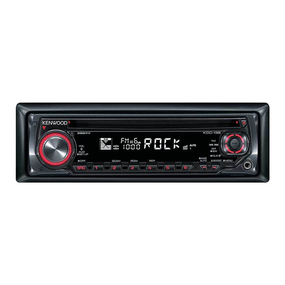
CD RECEIVER
KDC-138/138CR
KDC-139/139S
SERVICE MANUAL
Panel assy
KDC-138 (A64-4276-02)
Panel assy
KDC-139 (A64-4286-02)
KDC-139S (A64-4287-02)
Mounting hardware assy
(J21-9716-03)
DC cord
(E30-6415-15)
* Depends on the model. Refer to the parts list.
KDC-138
TDF SPARE-PANEL
MAIN UNIT NAME
KDC-138
KDC-139
KDC-138CR
KDC-139
KDC-139S
* Plastic cabinet assy
(A02-2736-03)
* Escutcheon
Lever
(B07-xxxx-xx)
(D10-4589-04) x2
This product complies with the
© 2007-9 PRINTED IN JA PAN
B53-0577-00 ( N ) 373
Panel assy
KDC-138CR (A64-4277-02)
TDF PARTS No.
Y33-2830-63
Y33-2830-64
Y33-2820-65
Y33-2820-66
* Carrying case
(W01-1692-05)
Screw set
(N99-1757-05)
This product uses Lead Free solder.
RoHS
directive for the European market.
KDC-138CR
TDF NAME
TDF-81D
TDF-81DCR
TDF-139
TDF-139S
Screw (4x16)
(N84-4016-48)
Advertisement
Table of Contents

Related Manuals for Kenwood KDC-138/138CR


Summary of Contents for Kenwood KDC-138/138CR
- Page 1 CD RECEIVER KDC-138/138CR KDC-139/139S SERVICE MANUAL © 2007-9 PRINTED IN JA PAN B53-0577-00 ( N ) 373 Panel assy Panel assy KDC-138 (A64-4276-02) KDC-138CR (A64-4277-02) KDC-138CR KDC-138 Panel assy KDC-139 (A64-4286-02) KDC-139S (A64-4287-02) TDF SPARE-PANEL MAIN UNIT NAME TDF PARTS No.
-
Page 2: Block Diagram
KDC-138/138CR/139/139S BLOCK DIAGRAM ELECTRIC UNIT (X34- ) Q901-903 ANT. DME1 DC-DET AM+B R103 TUNER FRONT-END MECHA PHONE PHONE SERVO+B POWER Q101 ACC-DET ACC DET Q103 BU DET BU-DET IC2 or IC3 Q102 DC-CN Q701,702 MUTE SURGE- E-VOL PHONE PRE-OUT PRE-OUT... - Page 3 KDC-138/138CR/139/139S COMPONENTS DESCRIPTION ● ELECTRIC UNIT (X34-564x-xx) Ref. No. Application / Function Operation / Condition / Compatibility System µ-COM Controls FM/AM tuner, the changer, CD mechanism, panel, volume and tone. IC2,3 E-VOL Controls the source, volume and tone. Power Supply IC Outputs 5Vx2, 8.1Vx2, 10.2V, P-CON and P-ANT.
- Page 4 KDC-138/138CR/139/139S COMPONENTS DESCRIPTION Ref. No. Application / Function Operation / Condition / Compatibility 5V-3.3V Level Shift Shifts 5V to 3.3V, or 3.3V to 5V. 5V-3.3V Level Shift Shifts 3.3V to 5V. BU3.3V SW Q6 is ON when Q8 or Q9 is ON.
- Page 5 KDC-138/138CR/139/139S MICROCOMPUTER’S TERMINAL DESCRIPTION ● SYSTEM µ-COM: IC1 on X34- (ELECTRIC UNIT) Truth Value Pin No. Pin Name Application Processing Operation Description Table LX DATA M I/O Data to slave unit Pull-down (GND) LX CLK I/O LX-BUS clock 125k~65kHz Not used Output L fi...
- Page 6 KDC-138/138CR/139/139S MICROCOMPUTER’S TERMINAL DESCRIPTION Truth Value Pin No. Pin Name Application Processing Operation Description Table CD LOEJ I/O CD motor control Refer to the truth value table CD MOTOR I/O CD motor control Refer to the truth value table VFD CE...
- Page 7 KDC-138/138CR/139/139S MICROCOMPUTER’S TERMINAL DESCRIPTION Truth Value Pin No. Pin Name Application Processing Operation Description Table TYPE2 Destination switching Refer to the truth value table If DC offset is found 20 times in 100ms with condition PWIC DC DET DC offset detection of over 1.0V, it will be judged as DC offset detected.
-
Page 8: Test Mode
KDC-138/138CR/139/139S TEST MODE ■ Example Description of display Description Disc EJECT times display. MAX 65535 (times) Disc EJECT times display While disc EJECT times is displayed, press and hold for ■5 2 seconds or longer to clear disc EJECT times. - Page 9 KDC-138/138CR/139/139S TEST MODE ■ Special displays when all lights are on in STANDBY source Description of display Description Common All lights ON. All lights ON. Destination terminal “TYPE” indicates system µ-com (IC1) destination, and shows condition indication real-time condition of the destination terminal.
- Page 10 KDC-138/138CR/139/139S TEST MODE • CD information display mode Description of display Description I2C com- I2C communication OK munication I2C communication NG status Mechanism error log 1 (Latest) 1 : X – XX: Error number. “– –” is displayed in case there is no error.
- Page 11 KDC-138/138CR/139/139S TEST MODE • TUNER preset operation Description of display Description Preset function Change to 98.3MHz with the preset key [4]. 8 . 3 • K3I forced switching Every time when [6] key is pressed in tuner FM source, switched in the following order: AUTO → Forced WIDE → Forced MIDDLE → Forced NARROW →...
- Page 12 KDC-138/138CR/139/139S TEST MODE ■ Audio-related test mode Procedure Note Enter audio adjustment mode (the initial item should be Fader, and then, Balance → Press the [AUD] key (main unit) Bass Level → Middle Level → Treble Level → SW Level → System Q → V-Offset →...
- Page 13 KDC-138/138CR/139/139S TEST MODE ■ LCD (ED1) short check Procedure Note All lights are off → Turns on odd and even terminals alternatively every 125ms (terminals that have a maximum number of grids) → Turns on only In the STANDBY source, press [ATT] key the odd terminals →...
- Page 14 KDC-138/138CR/139/139S TEST MODE ■ FM/AM channel space switching Procedure Note FM200kHz/AM10kHz ↔ FM50kHz/AM9kHz While Power OFF, press and hold [1] key and [5] key, and press [SRC] key to Power ON ■ ROM data transfer When replacing front-end (A1), this function is used to transfer E2PROM data (ROM correction, security and other data) to front-end (A1) to E2PROM of to mother unit (X34-), used for saving data, and, after completing replacement of front-end (A1), to recover data from the E2PROM of the mother unit (X34-), and for saving data to the new front-end (A1).
- Page 15 KDC-138/138CR/139/139S ROM DATA TRANSFER PROCESSES ■ Operation procedure When replacing front-end (A1) of mother unit (X34-), or when adding or replacing ROM correction (program correction with Operation procedure is different depending on the conditions. ROM IC (IC10)), the following activities are required.
- Page 16 KDC-138/138CR/139/139S ROM DATA TRANSFER PROCESSES Turn power on. Install new front-end (A1). Press and hold the [1] and [3] keys and press reset button. No ROM correction or other data status. (Enter the system in the test mode.) Press [B.BOOST] key. (ROM data System enters data transfer mode.)
- Page 17 KDC-138/138CR/139/139S ROM DATA TRANSFER PROCESSES 4. In case of applying a new ROM correction when front-end Turn power on. (A1) is replaced (There is ROM correction data.) Press and hold the [1] and [3] keys, press reset button. (Enter 5. In case of applying a new ROM correction even when the system in the test mode.)
- Page 18 KDC-138/138CR/139/139S ROM DATA TRANSFER PROCESSES Press [ ] key. (Exit ROM data transfer mode.) Turn power on. Turn power off. Press and hold the [1] and [3] keys press reset button. (Enter the system in the test mode.) Remove front-end (A1).
- Page 19 KDC-138/138CR/139/139S PC BOARD (COMPONENT SIDE VIEW) (FOIL SIDE VIEW) SWITCH UNIT SWITCH UNIT X16-616x-xx (J76-0454-02) X16-616x-xx (J76-0454-02) SW5V DATAS DATAL REMO R-CW R-CCW LED+B PAN5 X16-616x-xx X16-616x-xx Ref. No. Address Ref. No. Address Refer to the sche- Refer to the sche-...
- Page 20 KDC-138/138CR/139/139S PC BOARD (FOIL SIDE VIEW) ELECTRIC UNIT X34-564x-xx (J76-0457-02) W807 W100 W806 W805 R101 W102 W803 R102 W902 R910 R908 D103 Q901 R905 R106 R903 R901 R107 R801 D105 D901 W812 R108 D803 C902 C901 R803 C102 D106 R806...
- Page 21 KDC-138/138CR/139/139S 6 10 9 R604 X34-564x-xx Q701 Q702 Ref. No. Address C603 R710 R712 R803 C706 Q704 Q703 C705 W701 R492 Q101 Q102 C405 R793 W973 R491 Q103 R493 Q104 R404 R405 Q105 Q301 Q402 IC10 Q701 Q702 Q705 Q801...
- Page 22 KDC-138/138CR/139/139S PC BOARD (COMPONENT SIDE VIEW) CD PLAYER UNIT X32-5980-04 (J76-0448-02) X32-5980-04 Ref. No. Address Refer to the schematic diagram for the values of resistors and capacitors.
- Page 23 KDC-138/138CR/139/139S PC BOARD (FOIL SIDE VIEW) CD PLAYER UNIT X32-5980-04 (J76-0448-02) TRK+ FCS- SLD- SLD+ TRK- FCS+ D GND R108 BU5V R102 /MUTE IOP- 12EJE VREF LOS SW R103 IOP+ C16 C15 SPDL+ OSCIN SPDL- A3.3V SRVM FCLK OCDSEL TESTIN0...
- Page 24 KDC-138/138CR/139/139S ELECTRIC UNIT (X34-564x-xx) R606 1K REQ S TP98 ELECTRIC DISCHARGE R609 100 MUTE TP95 CIRCUIT for C805 (SVR) 14.4V R607 1K DATA S TP97 Q801 R605 100 TP99 R608 100 DATA M TP96 C807 R610 4.7K TP94 DC OFFSET TP903 7.3V...
- Page 25 KDC-138/138CR/139/139S TP315 C819 C820 7.3V 3.3V 0.6V TP316 7.3V BU5V R229 TP432 100K R223 5.0V 5.0V R598 5.0V R599 RESET IC R201 LX DATA M 0 or 1.6 or 2.5 or LX CLK 3.4 or 5.0V R202 100K 1.6V 4.8V...
- Page 26 CONTROL SW for IC4 D106-108,304-306, VFD+B may vary slight ly due to 601-606 : MTZJ6.8(B) D110 : BAV70W vari a tions between in di - SIGNAL LINE vid u al in stru ments or/and KDC-138/138CR/139/139S (1/2) GND LINE units. B LINE X34-564x-xx (3/3)
- Page 27 AUTO BOOST PANEL DETECT EJECT R30 100K C5 1 5.0V GND2 BACK VOUT GND1 LIGHT REMOTE CONTROL TP39 SENSOR AUX IN KDC-138/138CR/139/139S (2/2) B38-1183-05 (X16-616x-xx) MODEL DESTI- UNIT D10,11, R25, LC75857E-E D1,2,9,23 D12,19 D3-8 NAME NATION 13-18,21 PIC95603 RDT-131 0-01...
- Page 28 KDC-138/138CR/139/139S CD PLAYER UNIT (X32-598x-xx) D.GND 1.5V 16.934MHz ASEL OCDSEL 5V-3.3V 4.00pp LEVEL BCLK SHIFT 3.3V LRCK 3.3V 0-3.3V SRDATA 0-3.2V 3.3V R106 MUTE R MUTE L N.C. CORRECTION SRVMON1 SRVMON1 (NOT USED) SRVMON0 SRVMON0 RAMSEL FCLK 3.3V 3.3V ROMSEL...
- Page 29 KDC-138/138CR/139/139S A3.3V A.GND DTC114YUA 2SA1576A C71 10 2SB1295-E C72 0.1 C73 10 16.934MHz C74 0.1 A GND2 2.60pp 0.33 1000P VCOF 4.00pp C62 0.082 1.4V 2.45pp PLLFO 3.3V 1.4V 2SC4081 1000P PLLF 3.3V R77 82K 0.8V IREF C59 0.1 C60 0.022 1.7V...
- Page 30 KDC-138/138CR/139/139S EXPLODED VIEW (CD MECHANISM) DPU1 DFPC1 (X32) φ : N09-4460-15 M1.6x6.0 : N09-6317-05 M1.7x2.5 : N09-6004-15 M2x2 : N09-6007-15 φ 2x5(BLK) : N09-6051-15 1.6 WASHER : N19-2163-04 M2x2 : N39-2020-48 φ 2x3.5 : N09-6108-15 φ : N09-6155-15 Parts with the exploded numbers larger than 700 are not supplied.
- Page 31 KDC-138/138CR/139/139S EXPLODED VIEW (UNIT) DME1 : N24-3015-48 : N80-2006-48 : N80-2012-43 : N83-3005-48 : N86-2610-48 : N80-3010-48 : N83-3005-48 : N83-3020-48 : N86-2606-48 (X34) (X16-) (X16) (X16) (X16) (X34) (X16) (X16) (X16) (X34-) (X16) Depends on the models. Refer to the parts list.
-
Page 32: Parts List
KDC-138/138CR/139/139S PARTS LIST ✽ New parts Parts without Parts No. are not supplied. Les articles non mentionnes dans le Parts No. ne sont pas fournis. Teile ohne Parts No. werden nicht geliefert. Desti- Desti- Ref. No. Parts No. Description Ref. No. - Page 33 KDC-138/138CR/139/139S PARTS LIST CD PLAYER UNIT (X32-5980-04) IN CD MECHA Desti- Desti- Ref. No. Parts No. Description Ref. No. Parts No. Description nation nation CK73GB1C224K CHIP C 0.22UF RK73GB2A133J CHIP R J 1/10W CK73GB1H472K CHIP C 4700PF RK73GB2A183J CHIP R...
- Page 34 KDC-138/138CR/139/139S PARTS LIST ELECTRIC UNIT (X34-564x-xx) Desti- Desti- Ref. No. Parts No. Description Ref. No. Parts No. Description nation nation C306,307 CK73GB1C104K CHIP C 0.10UF R209,210 RD14BB2C471J J 1/6W C308 CD04AB0J470M ELECTRO 47UF 6.3WV R218 RK73GB2A223J CHIP R J 1/10W...
- Page 35 KDC-138/138CR/139/139S PARTS LIST ELECTRIC UNIT (X34-564x-xx) Desti- Desti- Ref. No. Parts No. Description Ref. No. Parts No. Description nation nation R808 RK73GB2A100J CHIP R J 1/10W D10-4910-13 ARM ASSY R891 RK73EB2E000J CHIP R J 1/4W D10-4911-23 LEVER ASSY R901,902 RK73GB2A334J...
- Page 36 KDC-138/138CR/139/139S PARTS LIST MECHANISM ASSY (X92-5860-06) DXM-6C06W Desti- Desti- Ref. No. Parts No. Description Ref. No. Parts No. Description nation nation DPU1 X93-2130-01 OPTICAL PICKUP ASSY K3 : KDC-138 K4 : KDC-138CR M6 : KDC-139 M7 : KDC-139S Indicates safety critical com po nents.
- Page 37 KDC-138/138CR/139/139S SPECIFICATIONS (KDC-138/138CR) FM tuner section Audio section Frequency range Maximum output power ..........50W x 4 200kHz space ........87.9MHz~107.9MHz Full Bandwidth Power (at less than 1% THD) ... 22W x 4 50kHz space (KDC-138CR) ....87.5MHz~108.0MHz Speaker Impedance ............4~8Ω Usable sensitivity (S/N=30dB) ....9.3dBf (0.8µV/75Ω) Tone action Quieting Sensitivity (S/N=50dB) ....15.2dBf (1.6µV/75Ω)
- Page 38 Spindle speed .......... 500~200rpm (CLV) Wow & Flutter ........Below Measurable Limit Frequency response (±1dB) ......20Hz~20kHz KENWOOD follows a policy of continuous advancements Total harmonic distortion (1kHz) ........0.01% in development. For this reason specifications may be Signal to Noise ratio (1kHz) ........... 93dB changed without notice.