Table of Contents
Advertisement
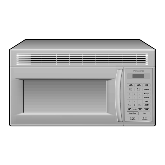
Service Manual
Specifications
ITEM
Power Source
Power Requirement:
Output:
Microwave Frequency:
Timer:
Outside Dimensions:
Oven Cavity Dimensions:
Weight:
Specifications subject to change without notice.
NN-S251WL
NN-S251BL
120 V AC, 60 Hz
13.5 Amps, 1,550 W
1000 W: Full Power (IEC 60705)
2,450 MHz
99 min. 99 sec.
29
15 /16"
(W)
16
7 /16"
(H)
15
X
X
760mm(W)
418mm(H)
X
19
7 /8"
(W)
8
15 /16"
(H)
14
X
X
505mm(W)
227mm(H)
X
Approx. 52 lbs (23.5 kg)
2001 Matsushita Electric Industrial Co., Ltd. All
rights reserved. Unauthorized copying and distribution
is a violation of law.
ORDER NO. MOD 0106244C1
E2
Microwave Oven
APH
3 /8"
(D)
385mm(D)
X
3 /16"
(D)
360mm(D)
X
Advertisement
Table of Contents

Related Manuals for Panasonic NN-S251WL


Summary of Contents for Panasonic NN-S251WL
-
Page 1: Microwave Oven
ORDER NO. MOD 0106244C1 Service Manual Microwave Oven NN-S251WL NN-S251BL Specifications ITEM Power Source 120 V AC, 60 Hz Power Requirement: 13.5 Amps, 1,550 W Output: 1000 W: Full Power (IEC 60705) Microwave Frequency: 2,450 MHz Timer: 99 min. 99 sec. -
Page 2: Safety Precautions
5. Any serviceman who learns of any accident pertaining to microwave radiation leakage including the oven operating with open door should immediately notify the appropriate address listed below and Center for Devices and Radiological Health, DHHS. IN U.S.A. Panasonic Services Company IN PUERTO RICO (PASC) 50 Meadowland Parkway,... -
Page 3: Table Of Contents
FOREWORD Read this Manual carefully. Failure to adhere to or observe the information in this Manual may result in exposing yourself to the Microwave Energy normally contained within the oven cavity. TABLE OF CONTENTS (Page) SAFETY PRECAUTIONS ......................Inside front page SPECIFICATIONS............................ -
Page 4: Specifications
SPECIFICATIONS Rated Power Consumption 1,550W maximum (Microwave oven+Cook top lamps+Ventilation fan) ± Frequency 2,450 MHz 50 MHz Power Supply 120 VAC, 60 Hz Rated Current 13.5 Amp. (Microwave oven+Cook top lamps+Ventilation fan) Magnetron Cooling Forced Air Cooling Rectification Rectification Voltage Double Half-Wave Door Sealing Choke System Safety Devices... -
Page 5: Cautions
CAUTIONS Unlike other appliances, the microwave oven is MICROWAVE RADIATION high-voltage and high-current equipment. Personnel should not be exposed to the Though it is free from danger in ordinary use, microwave energy which may radiate from the extreme care should be taken during repair. magnetron or other microwave generating device if it is improperly used or connection. -
Page 6: Installations
INSTALLATIONS BEFORE YOU BEGIN, READ THE FOLLOWING INSTRUCTIONS COMPLETELY AND CAREFULLY. PRECAUTIONS ON INSTALLATION A. Plug the power supply cord into a 120V AC, 60Hz, single-phase power source with a capacity of 15A or 20A. B. Avoid placing the unit in a location where there is direct heat or splashing water. -
Page 7: Feature Diagram
FEATURE DIAGRAM Identification Plate & Menu Label Oven Air Vent Glass Tray See-through Oven Window Door Handle Cover (do not remove) Door Safety Lock System Control Panel Cooktop Light Grease Filter... -
Page 8: Control Panel
CONTROL PANEL 1. Display Window : The Display includes a clock and 10. Timer Off Pad : Touch this pad to stop timer function. indicators to tell you time of day, cooking time settings and cooking functions selected. 11. Function Pad : Touch this pad to change the oven’s default settings for sound, clock, display speed, defrost 2. -
Page 9: Overall Circuit Diagram
OVERALL CIRCUIT DIAGRAM SCHEMATIC DIAGRAM... -
Page 10: Matrix Circuit For Touch Key Board
MATRIX CIRCUIT FOR TOUCH KEY BOARD... -
Page 11: General Information For Service
GENERAL INFORMATION FOR SERVICE FEATURES AND SPECIFICATIONS GENERAL PRECAUTIONS IN USE FEATURES A. Never operate the unit when it is empty. Operating the oven with no load may shorten the A. The safety systems incorporated in this model are: life of the magnetron. Whenever cooking dry foods (1) Primary interlock switch (dried fish, bread, etc.) or a small amount of food, (2) Secondary interlock switch... -
Page 12: Service Information
SERVICE INFORMATION PRECAUTIONS AND REPAIR SERVICE TIPS PRELIMINARY (3) Do not operate the unit until it is completely A. SINCE NEARLY 2,100 VOLTS EXISTS IN SOME repaired, if any of the following conditions exist. CIRCUITS OF THIS UNIT REPAIRS SHOULD BE The unit must not be operated. -
Page 13: Procedure For Measuring Microwave Energy Leakage
PROCEDURE FOR MEASURING MICROWAVE ENERGY LEAKAGE (D) Tap the start pad or set the timer and with the WARNING magnetron oscillating, measure the leakage by Check for radiation leakage after every servicing. holding the probe perpendicular to the surface being Should the leakage be more than 2 mW/cm inform measured. -
Page 14: Power Output Measurement
MEASUREMENT WITH THE OUTER CASE NOTE WHEN MEASURING (1) Do not exceed meter full scale deflection. REMOVED (2) The test probe must be removed no faster than (1) When you replace the magnetron, measure for 1 inch/sec (2.5cm/sec) along the shaded area, microwave energy leakage before the outer case otherwise a false reading may result. -
Page 15: Disassembly Instructions
DISASSEMBLY INSTRUCTIONS IMPORTANT NOTES: (4) Remove 3 screws securing the circuit board. UNIT MUST BE DISCONNECTED FROM ELEC-TRICAL OUTLET WHEN MAKING REPAIRS, RE-PLACEMENTS, ADJUSTMENTS AND CONTIN-UITY CHECKS. WAIT AT LEAST ONE MINUTE, UNTIL THE HIGH VOLTAGE CAPACITOR IN THE HIGH VOLTAGE POWER SUPPLY HAS FULLY DISCHARGED. - Page 16 HOW TO INSERT THE F.P.C. CONNECTOR HOW TO REMOVE THE F.P.C. CONNECTOR Follow the steps below as illustrated in Figures 6 Follow the steps below as illustrated in Figures 4 and 7 to insert the F.P.C. connector. and 5 to remove the F.P.C. connector. (1) Insert the F.P.C.
- Page 17 B. REMOVING THE OUTER CASE(Figure 8) (1) Remove the vent grille by removing two screws (5) Remove the base plate by removing six screws securing it to the outer case. securing it to the outer case. Remove the Mount (2) Remove two screws securing it to the front from the out case by removing two screws bracket.
- Page 18 C REMOVING THE DOOR INTERLOCK SWITCHES (Figures 9,10) (1) Disconnect the wire leads from the interlock switches. (2) Remove two screws securing the Door Hook. (3) Make necessary replacements and check microwave energy leakage according to Door Hook “ADJUSTMENT PROCEDURE” on page 7-12. Secondary Interlock Switch Door Hook...
- Page 19 D. REMOVING MAGNETRON NOTES: • When removing the magnetron, make sure that its (Figures 11 Through 13) dome does not hit any adjacent parts, or it may be (1) Remove vent grille. damaged. (2) Remove mount. (3) Remove outer case. •...
- Page 20 E. REMOVING DOOR (Figure 14) (1) Remove the vent grille by removing two screws securing it to the Outer Case loosening. (2) Lift up and draw the door. NOTES: • After replacing the door, be sure to check that the primary interlock switch, the secondary interlock switch and the interlock monitor switch is in good operating normally.
- Page 21 G. ASSEMBLING DOOR (1) When mounting the door assembly to the oven (3) Carefully pull the ventilation motor ASS'Y out of assembly, be sure to adjust the door assembly the microwave oven. (See Figure 18) parallel to the chassis. Also adjust so the door has no play between the inner door surface and oven frame assembly.
- Page 22 I. REMOVING THE TURNTABLE MOTOR NOTES: • Remove the leadwire from the turntable motor VERY (1) Remove the turntable. CAREFULLY. (2) Remove the turntable shaft VERY CAREFULLY • Be sure to grasp the connector not the wires when with a slotted screwdriver. (Figure 19) removing.
-
Page 23: Interlock System
INTERLOCK SYSTEM INTERLOCK SYSTEM INTERLOCK MECHANISM The door lock mechanism is a device which has been specially designed to eliminate completely microwave activity when the door is opened during cooking and thus to prevent the danger resulting from the microwave leakage. - Page 24 TEST THE LATCH AND SWITCH SEQUENCE (5) Open the oven door slowly. Watch the door latch, (7) When you achieve the proper sequence of the Secondary Switch. Release Rod and Lever on switches in Steps 5 and 6, tighten the latch board the switches to make sure they are zero to the screws at that point.
-
Page 25: Interlock Continuity Test
INTERLOCK CONTINUITY TEST A. PRIMARY INTERLOCK SWITCH TEST B. SECONDARY INTERLOCK SWITCH TEST Disconnect the wire lead from the secondary When the door is opened slowly, an audible click switch. should be heard at the same time or successively Connect the ohmmeter leads to the common at intervals and the latches should activate the (COM) and normally open (NO) terminals of the switches with an audible click. -
Page 26: Test And Checkout Procedures And Trouble Shooting
TEST AND CHECKOUT PROCEDURES, AND TROUBLE SHOOTING - CAUTIONS - - DISCONNECT THE POWER SUPPLY CORD Filament Winding FROM THE WALL OUTLET WHENEVER REMOVINGING THE CABINET FROM THE UNIT. PROCEED WITH THE TESTS ONLY AFTER Secondary DISCHARGING THE HIGH VOLTAGE CAPACITOR Winding AND REMOVING THE WIRE LEADS FROM THE PRIMARY WINDING OF THE HIGH VOLTAGE... - Page 27 COMPONENTS TEST PROCEDURES RESULTS Measure the resistance: Normal reading: (1) Terminal to terminal Momentarily indicates several ohms, and then gradually returns to infinite ohms. Abnormal reading: Ohm- Indicates continuity or infinite ohms meter from the beginning. HIGH-VOLTAGE Figure 24-a CAPACITOR (2) Terminal to case Normal readings: Infinite.
- Page 28 COMPONENTS TEST PROCEDURES RESULTS Measure the resistance between terminal When When not pins of connector KEY CONNECTOR. Resistance touched touched NOTE: value Less than More than When reconnecting the FPC connector, 400 ohms 1 mega ohm make sure that the holes on the FPC connector are properly engaged with hooks on the plastic fastener.
-
Page 29: Checkout Procedures
COMPONENTS TEST PROCEDURES RESULTS POWER Check for continuity of relay 7 with an LEVEL ohm-meter. (Remove wire leads from relay 7 and 4 sec 18 sec operate the unit.) 6 sec 16 sec Relay 7 8 sec 14 sec 10 sec 12 sec RELAY7 12 sec... - Page 30 (2) CHECKOUT PROCEDURES FOR RELAY. - PROBLEM (A) - Vent fan motor and oven lamp turn on without touching START key when the door is closed. Remove the mate connector of I/O GOOD CON from the circuit board. Does the unit still operate? Replace the Defective circuit board...
- Page 31 (3) CHECKOUT PROCEDURES FOR CIRCUIT BOARD The following symptoms indicate a defective circuit 6) Wrong figures appear. board. 7) The figures of all digits. 1) 1) The start function fails to operate but the high 8) Some of the indicators do no flicker light up. voltage Systems, the interlock switches, the door 9) The clock does not keep time properly.
- Page 32 7-21...
- Page 33 7-22...
- Page 34 7-23...
- Page 35 7-24...
-
Page 36: Schematic Diagram Of Pcb
SCHEMATIC DIAGRAM OF P.C.B... -
Page 37: Printed Circuit Board
PRINTED CIRCUIT BOARD... -
Page 38: Exploded View
EXPLODED VIEW MODEL : NN-S251 DOOR PARTS... -
Page 39: Escutcheon Base Assembly
ESCUTCHEON BASE ASSEMBLY... -
Page 40: Oven Cavity Parts
OVEN CAVITY PARTS... - Page 41 DOOR HOOK PARTS...
- Page 42 INTERIOR PARTS(I)
- Page 43 INTERIOR PARTS (II)
- Page 44 INSTALLATION PARTS VINYL...