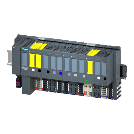
Siemens Simatic ET 200SP Manual
Analog input module ai 2xu st
Hide thumbs
Also See for Simatic ET 200SP:
- System manual (320 pages) ,
- Manual (270 pages) ,
- Operating instructions manual (166 pages)
Table of Contents
Advertisement
Advertisement
Table of Contents

Related Manuals for Siemens Simatic ET 200SP


Summary of Contents for Siemens Simatic ET 200SP
- Page 2 ___________________ Analog input module AI 2xU ST Preface (6ES7134-6FB00-0BA1) ___________________ Documentation guide ___________________ SIMATIC Product overview ___________________ Wiring ET 200SP Analog input module AI 2xU ST ___________________ (6ES7134-6FB00-0BA1) Parameters/address space ___________________ Interrupts/diagnostics alarms Manual ___________________ Technical specifications ___________________ Parameter data record ___________________ Representation of analog values...
- Page 3 Note the following: WARNING Siemens products may only be used for the applications described in the catalog and in the relevant technical documentation. If products and components from other manufacturers are used, these must be recommended or approved by Siemens. Proper transport, storage, installation, assembly, commissioning, operation and maintenance are required to ensure that the products operate safely and without any problems.
-
Page 4: Preface
Siemens recommends strongly that you regularly check for product updates. For the secure operation of Siemens products and solutions, it is necessary to take suitable preventive action (e.g. cell protection concept) and integrate each component into a holistic, state-of-the-art industrial security concept. -
Page 5: Table Of Contents
Table of contents Preface ..............................4 Documentation guide ..........................6 Product overview ............................ 9 Properties ..........................9 Wiring ..............................11 Wiring and block diagram ....................... 11 Parameters/address space ........................13 Measuring types and ranges ....................13 Parameters ..........................14 Explanation of the parameters ....................16 Address space ........................ -
Page 6: Documentation Guide
Documentation guide The documentation for the SIMATIC ET 200SP distributed I/O system is arranged into three areas. This arrangement enables you to access the specific content you require. Basic information The system manual describes in detail the configuration, installation, wiring and commissioning of the SIMATIC ET 200SP. - Page 7 Documentation guide Manual Collection ET 200SP The Manual Collection contains the complete documentation on the SIMATIC ET 200SP distributed I/O system gathered together in one file. You can find the Manual Collection on the Internet (http://support.automation.siemens.com/WW/view/en/84133942). "mySupport" With "mySupport", your personal workspace, you make the most of your Industry Online Support.
- Page 8 With the TIA Selection Tool, you can generate a complete order list from your product selection or product configuration. You can find the TIA Selection Tool on the Internet (http://w3.siemens.com/mcms/topics/en/simatic/tia-selection-tool). Analog input module AI 2xU ST (6ES7134-6FB00-0BA1) Manual, 12/2015, A5E36104728-AA...
-
Page 9: Product Overview
Product overview Properties Article number 6ES7134-6FB00-0BA1 View of the module ① ⑦ Module type and name Function class ② ⑧ LED for diagnostics Color coding module type ③ ⑨ 2D matrix code Function and firmware version ④ ⑩ Wiring diagram Color code for selecting the color identification labels ⑤... - Page 10 ● Color identification labels ● Reference identification label ● Shield connector See also You can find additional information on the accessories in the ET 200SP distributed I/O system (http://support.automation.siemens.com/WW/view/en/58649293) system manual. Analog input module AI 2xU ST (6ES7134-6FB00-0BA1) Manual, 12/2015, A5E36104728-AA...
-
Page 11: Wiring
This section includes the block diagram of the AI 2xU ST module with the terminal assignments. You can find information on wiring the BaseUnit in the ET 200SP distributed I/O system (http://support.automation.siemens.com/WW/view/en/58649293) system manual. Note The load group of the module must begin with a light-colored BaseUnit. Keep this in mind also during the configuration. - Page 12 Wiring 3.1 Wiring and block diagram Wiring: Voltage measurement 2-wire connection The following figure shows the block diagram and an example of the terminal assignment of the analog input module AI 2xU ST on the BaseUnit BU type A0/A1. ① 2-wire connection for voltage measurement Voltage input positive, channel n ②...
-
Page 13: Parameters/Address Space
Parameters/address space Measuring types and ranges The analog input module AI 2×U ST has the following measuring ranges: Table 4- 1 Measuring ranges Measurement type Measuring range Resolution Voltage ± 5 V 16 bits incl. sign ± 10 V 16 bits incl. sign 1 to 5 V 15 bits 0 to 10 V... -
Page 14: Parameters
Parameters/address space 4.2 Parameters Parameters Parameters of the AI 2xU ST The effective range of the configurable parameters depends on the type of configuration. The following configurations are possible: ● Central operation with an ET 200SP CPU ● Distributed operation on PROFINET IO in an ET 200SP system ●... - Page 15 Parameters/address space 4.2 Parameters Parameter Range of values Default Parameter Effective range with configuration reassign- software, e.g. STEP 7 ment in (TIA Portal) GSD file GSD file PROFINET IO PROFIBUS DP Interference frequency 50 Hz (60 ms) Channel Module 60 Hz (50 ms) •...
-
Page 16: Explanation Of The Parameters
Parameters/address space 4.3 Explanation of the parameters Explanation of the parameters Diagnostics: No supply voltage L+ Enabling of the diagnostics for no or insufficient supply voltage L+. Diagnostics: Short-circuit to ground Diagnostics are enabled when both input signals are short-circuited in the range 1 to 5 V. The short-circuit and underflow diagnostics can be activated simultaneously. - Page 17 Parameters/address space 4.3 Explanation of the parameters Smoothing The individual measured values are smoothed by filtering. The smoothing can be set in 4 levels. Smoothing time = number of module cycles (k) × cycle time of the module. The following figure shows how many module cycles it takes for the smoothed analog value to approach 100%, depending on the configured smoothing.
- Page 18 A potential group ends with the dark-colored BaseUnit, which follows a light-colored BaseUnit or server module in the station configuration. See also You can find additional information in the system manual ET 200SP distributed I/O system (http://support.automation.siemens.com/WW/view/en/58649293). Analog input module AI 2xU ST (6ES7134-6FB00-0BA1) Manual, 12/2015, A5E36104728-AA...
-
Page 19: Address Space
Parameters/address space 4.4 Address space Address space Configuration options The following configurations are possible: ● Configuration 1: Without value status ● Configuration 2: With value status Evaluating the value status If you enable the value status for the analog module, an additional byte is occupied in the input address space. -
Page 20: Interrupts/Diagnostics Alarms
Interrupts/diagnostics alarms Status and error display LED display The following figure shows you the LED display of the AI 2xU ST. ① DIAG (green/red) ② Channel status (green) ③ PWR (green) Image 5-1 LED display Analog input module AI 2xU ST (6ES7134-6FB00-0BA1) Manual, 12/2015, A5E36104728-AA... - Page 21 Interrupts/diagnostics alarms 5.1 Status and error display Meaning of the LEDs The following tables show the meaning of the status and error displays. Corrective measures for diagnostics alarms can be found in section Diagnostics alarms (Page 22). DIAG LED Table 5- 1 Error display of the DIAG LED DIAG LED Meaning...
-
Page 22: Interrupts
Interrupts/diagnostics alarms 5.2 Interrupts Interrupts The AI 2×U ST analog input module supports diagnostics interrupts. Diagnostics interrupts The module generates a diagnostic interrupt at the following events: ● Short-circuit (voltage 1 V to 5 V) ● High limit violated ● Low limit violated ●... -
Page 23: Technical Specifications
Technical specifications Technical specifications Technical specifications of the AI 2×U ST 6ES7134-6FB00-0BA1 General information Product type designation ET 200SP, AI 2xU Standard Firmware version V1.0 FW update possible • Usable BaseUnits BU type A0, A1 Color code for module-specific color identification CC00 label Product function... - Page 24 Technical specifications 6.1 Technical specifications 6ES7134-6FB00-0BA1 Power loss Power loss, typ. 0.9 W Address area Address space per module Address space per module, max. 4 bytes; + 1 byte for QI information Analog inputs Number of analog inputs Maximum permissible input voltage for voltage 30 V input (destruction limit) Cycle time (all channels), min.
- Page 25 Technical specifications 6.1 Technical specifications 6ES7134-6FB00-0BA1 Encoders Connection of the signal transmitters For voltage measurement Errors/accuracies Linearity error (in relation to input range), (+/-) 0.01% Temperature error (in relation to input range), (+/-) 0.005%/K Crosstalk between inputs, min. -50 dB Repeat accuracy in settled state at 25 °C (in 0.05% relation to input range), (+/-)
- Page 26 Between the inputs (UCM) 10 Vss Isolation Isolation tested with 707 V DC (type test) Dimensions Width 15 mm Weights Weight, approx. 31 g Dimension drawing See manual ET 200SP BaseUnits (http://support.automation.siemens.com/WW/view/en/59753521) Analog input module AI 2xU ST (6ES7134-6FB00-0BA1) Manual, 12/2015, A5E36104728-AA...
-
Page 27: Parameter Data Record
Parameter data record Dependencies when configuring with GSD file When configuring the module with a GSD file, remember that the settings of some parameters are dependent on each other. Configuring with a PROFINET GSD file The table lists the properties and their dependencies on the measurement type and measuring range for PROFINET. -
Page 28: Parameter Assignment And Structure Of The Parameter Data Record
Parameter data record A.2 Parameter assignment and structure of the parameter data record Parameter assignment and structure of the parameter data record Parameter assignment in the user program You can reassign the module parameters in RUN. For example, the voltage or current values of selected channels can be changed in RUN without having an effect on the other channels. - Page 29 Parameter data record A.2 Parameter assignment and structure of the parameter data record Header information The figure below shows the structure of the header information. Image A-2 Header information Parameters The following figure shows the structure of the parameters for channels 0 and 1. You enable a parameter by setting the corresponding bit to "1".
- Page 30 Parameter data record A.2 Parameter assignment and structure of the parameter data record Image A-3 Structure of bytes x to x+17 for channels 0 and 1 Codes for measurement types The following table contains the codes for the measuring types of the analog input module. You must enter these codes at byte x (see previous figure).
- Page 31 Parameter data record A.2 Parameter assignment and structure of the parameter data record Error transmitting the data record The module always checks all values of the transmitted data record. The module applies the values from the data record only when all values have been transmitted without errors. The WRREC instruction for writing data records returns the appropriate error codes if there are errors in the STATUS parameter.
-
Page 32: Representation Of Analog Values
Representation of analog values Representation of analog values This appendix shows the analog values for all measuring ranges that you can use with the analog input module. Measured value resolution The resolution of the analog values differs depending on the analog module and its assigned parameters. -
Page 33: Representation Of Input Ranges
Representation of analog values B.2 Representation of input ranges Representation of input ranges In the following tables, you can find the digitized representation of the bipolar and unipolar input ranges. The resolution is 16 bits. Table B- 2 Bipolar input ranges Dec. -
Page 34: Representation Of Analog Values In Voltage Measuring Ranges
Representation of analog values B.3 Representation of analog values in voltage measuring ranges Representation of analog values in voltage measuring ranges Voltage measuring range ±10 V to ±5 V Table B- 4 Voltage measuring range ±10 V to ±5 V System Voltage measuring range Range...