
Related Manuals for Siemens MicroSAM


Summary of Contents for Siemens MicroSAM
- Page 1 Process Gas Chromatograph MicroSAM Operating Instructions · 03/2012 Process Gas Chromatography...
- Page 3 Purpose of this documentation General information Description Process analytics Mounting Process Gas Chromatograph Commissioning and MicroSAM operation Service and maintenance Operating Instructions Spare parts/accessories Examples Technical data Dimension drawings Appendix 7KQ3101 06/2012 C79000-G5376-C560-07...
- Page 4 Note the following: WARNING Siemens products may only be used for the applications described in the catalog and in the relevant technical documentation. If products and components from other manufacturers are used, these must be recommended or approved by Siemens. Proper transport, storage, installation, assembly, commissioning, operation and maintenance are required to ensure that the products operate safely and without any problems.
-
Page 5: Table Of Contents
Directives for operation ........................15 Qualified personnel ........................17 Limitation of liability for external accessories................17 Final shutdown and disposal......................17 Description............................... 19 Applications..........................19 Product features...........................20 MicroSAM design.........................21 Rating plate design ........................22 Functional description of the electronics..................23 Functions............................25 3.6.1 Gas flow charts ..........................26 3.6.2 Analysis module ...........................28... - Page 6 6.3.1 Removal of electronic modules....................88 6.3.2 Installation of electronic modules....................92 Conversion of MicroSAM basic device AS09................94 6.4.1 Preparation for use of analysis modules of type A ..............94 6.4.2 Restoring of data for AS09 type A ....................96 6.4.3...
- Page 7 Advantages of live switching......................114 A.1.2 Live switching function .......................115 ESD guidelines ..........................120 EC Declaration of Conformity ....................122 A marking in accordance with KC (Korea).................122 Service and Support ........................123 List of abbreviations ........................124 Glossary ..............................127 Index..............................133 MicroSAM Operating Instructions, 06/2012, C79000-G5376-C560-07...
- Page 8 Table of contents MicroSAM Operating Instructions, 06/2012, C79000-G5376-C560-07...
-
Page 9: Purpose Of This Documentation
All obligations on the part of Siemens AG are contained in the respective sales contract which also contains the complete and solely applicable warranty conditions. Any statements contained herein do not create new warranties or modify the existing warranty. - Page 10 Purpose of this documentation MicroSAM Operating Instructions, 06/2012, C79000-G5376-C560-07...
-
Page 11: General Information
Transportation in accordance with proper procedures Proper storage Proper installation and assembly Careful operation and maintenance To avoid injury to persons and damage to the device, please observe the information in the manual. MicroSAM Operating Instructions, 06/2012, C79000-G5376-C560-07... - Page 12 Avoided corrosion and damage of the connection lines resulting from permanent contact with the following substances: Nitric acid Hydrochloric acid Carbon bisulfide Ethanol Formic acid Petroleum spirit Hydraulic oil Isopropanol MicroSAM Operating Instructions, 06/2012, C79000-G5376-C560-07...
-
Page 13: Transportation
If the chromatograph is transported or shipped without this metal bracket, the warranty is nullified. Exception: The metal bracket is not required if the chromatograph is mounted in a protective casing approved by Siemens. In this case, transportation or shipping of the chromatograph is only permissible in this protective casing. MicroSAM... -
Page 14: Protection Against Explosion
The test certificate for your explosion-proof gas chromatograph only applies to the original configuration as well as to connection and installation according to the switching and piping plans of Siemens AG. Changing one or more components will void the explosion protection for your device. - Page 15 Acetylene and ethylene oxide can be present in a concentration up to 100%. The permissible ambient temperature range is -30° to +55° C. The temperature range for continuous operation is -20 °C to +50 °C. MicroSAM Operating Instructions, 06/2012, C79000-G5376-C560-07...
- Page 16 General information 2.4 Protection against explosion Table 2- 1 Case examples for explosion protection Case Concen- Transient Permis Sample External Substances Process MicroSAM SITRANS tration of concen- sible pressure flame that are medium (7KQ3101) oxygen tration of carrier (absolute) arrester...
-
Page 17: Directives For Operation
CLASS I, ZONE 1 GROUPS IIC T4 ENCLOSURE TYPE 4X / IP65 2.4.2 Directives for operation Switching on the chromatograph Only switch on the power supply to the device if this has been closed correctly. MicroSAM Operating Instructions, 06/2012, C79000-G5376-C560-07... - Page 18 Maintenance and repair of components WARNING Observe the directive Observe the regulations of directive RL 99/92/EU (ATEX 137) when carrying out maintenance and repairs on parts associated with the explosion protection. MicroSAM Operating Instructions, 06/2012, C79000-G5376-C560-07...
-
Page 19: Qualified Personnel
Insufficient knowledge of the operating instructions, or the complete absence thereof, result in the deletion of all liability claims with regard to Siemens AG. We therefore recommend owners to have the instruction of personnel confirmed in writing. - Page 20 General information 2.7 Final shutdown and disposal MicroSAM Operating Instructions, 06/2012, C79000-G5376-C560-07...
-
Page 21: Description
● Metals, basic materials, cement ● Glass The process gas chromatograph is a device for determining the concentration of selected components in a process gas, and is used for measuring and analysis methods associated with process analysis. MicroSAM Operating Instructions, 06/2012, C79000-G5376-C560-07... -
Page 22: Product Features
● Device can be mounted directly at the sampling point, since it has a rugged and compact design and only a carrier gas supply and little power are required. ● Modular design and low energy consumption, thus low operating costs. MicroSAM Operating Instructions, 06/2012, C79000-G5376-C560-07... -
Page 23: Microsam Design
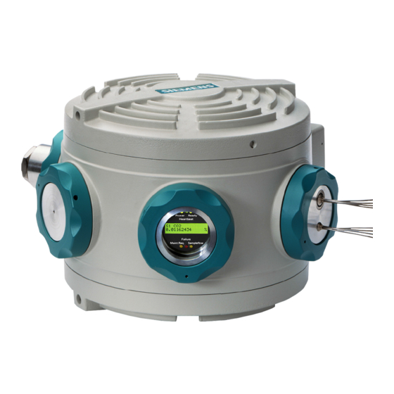
Description 3.3 MicroSAM design MicroSAM design The following illustration provides an overview of the most important MicroSAM modules. ① ⑧ MicroSAM housing Gas connections with blanking plugs ② ⑨ Main cover Pressure controller ③ ⑩ Analysis module RSP module ④... -
Page 24: Rating Plate Design
① ⑤ Vendor CSA marking with CSA data ② ⑥ CE marking IEC marking ③ ⑦ Ex marking with Ex data Serial number and release version (RV) ④ Consult operating instructions Figure 3-2 Rating plate MicroSAM Operating Instructions, 06/2012, C79000-G5376-C560-07... -
Page 25: Functional Description Of The Electronics
Description 3.5 Functional description of the electronics Functional description of the electronics Overview The following block diagram shows the basic design of the electronics: MicroSAM Operating Instructions, 06/2012, C79000-G5376-C560-07... - Page 26 Description 3.5 Functional description of the electronics RSP (real-time signal processing) and CAC (communication and analytical control) Figure 3-3 RSP and CAC EPC (electronic pressure control) Figure 3-4 MicroSAM Operating Instructions, 06/2012, C79000-G5376-C560-07...
-
Page 27: Functions
A01 124 ES04 or higher. The supplement ES04 identifies product version 4 of the analysis module. From release version 9 (AS09) onwards of the MicroSAM basic unit, the version eLive is produced. In this case the basic unit has an additional membrane valve function 5 for purging the sample loop. -
Page 28: Gas Flow Charts
3.6 Functions 3.6.1 Gas flow charts As of AS09, the MicroSAM gas chromatograph is manufactured as two versions: Live and eLive. Solenoid valves control the respective functions in the multi-membrane valve. Gas flow chart for analysis modules A01 - A11 (live injection) A01 ... - Page 29 Solenoid valve 4 (MV4) Membrane valve function 4: "Inject" Solenoid valve 5 (MV5) Membrane valve function 5: "Purge sample loop" Electronic pressure control Thermal conductivity detector Figure 3-6 Analysis module of type D with eLive injection MicroSAM Operating Instructions, 06/2012, C79000-G5376-C560-07...
-
Page 30: Analysis Module
● From product version 05 (ES05) onwards, the system for numbering the columns has been changed. Analysis modules up to ES04 The analysis modules up to ES04 are suitable for separating the following components: Figure 3-7 Analysis modules A01 to A03 up to ES04 MicroSAM Operating Instructions, 06/2012, C79000-G5376-C560-07... - Page 31 Description 3.6 Functions Figure 3-8 Analysis modules A04 to A10 up to ES04 MicroSAM Operating Instructions, 06/2012, C79000-G5376-C560-07...
- Page 32 Description 3.6 Functions Analysis modules from ES05 onwards The analysis modules from ES05 onwards are suitable for separating the following components: Figure 3-9 Analysis modules A01/D01 to A05/D05 from ES05 onwards MicroSAM Operating Instructions, 06/2012, C79000-G5376-C560-07...
- Page 33 Description 3.6 Functions Figure 3-10 Analysis modules A06/D06 to A11/D11 from ES05 onwards MicroSAM Operating Instructions, 06/2012, C79000-G5376-C560-07...
-
Page 34: Example Of Time Switching Commands
Description 3.6 Functions 3.6.3 Example of time switching commands ... t Preparation of measurement Purge sample loop Inject Empty sample loop completely Purge sample loop with sample Backflush Figure 3-11 Example of time switching commands MicroSAM Operating Instructions, 06/2012, C79000-G5376-C560-07... -
Page 35: Thermal Release In The Analysis Module
3. Injecting (Page 41) 4. Empty sample loop completely (Page 43) 5. Purge sample loop with sample (Page 44) 6. Cut - start (Page 45) 7. Cut - end (Page 46) 8. Backflushing (Page 47) MicroSAM Operating Instructions, 06/2012, C79000-G5376-C560-07... - Page 36 The following table lists the significance of the colors for the gas lines used in the Section "Measuring sequence". Color of gas line Assignment Sample gas Blue Carrier gas Violet Mixture of sample gas and carrier gas MicroSAM Operating Instructions, 06/2012, C79000-G5376-C560-07...
-
Page 37: Preparation Of Measurement
Preparation of measurement Note Time switching points The time switching points shown on the following pages all depend on the type of application. Only the time switching point t for the injection is always zero. MicroSAM Operating Instructions, 06/2012, C79000-G5376-C560-07... - Page 38 Description 3.6 Functions Purging of membrane valve Time switching point t = -20 s Live Flush loop Sample Backflush Injection eLive Flush loop_1 Sample Backflush Injection Flush loop_2 MicroSAM Operating Instructions, 06/2012, C79000-G5376-C560-07...
- Page 39 Description 3.6 Functions Backflushing of system Time switching point t = -19 s Live Flush loop Sample Backflush Injection eLive Flush loop_1 Sample Backflush Injection Flush loop_2 MicroSAM Operating Instructions, 06/2012, C79000-G5376-C560-07...
- Page 40 Description 3.6 Functions Backflushing of system finished Time switching point t = -13 s Live Flush loop Sample Backflush Injection eLive Flush loop_1 Sample Backflush Injection Flush loop_2 MicroSAM Operating Instructions, 06/2012, C79000-G5376-C560-07...
-
Page 41: Purge Sample Loop
3.6.5.2 Purge sample loop Live Time switching point t = -10 s. The contents of the sample loop are transferred to the outlet "Backflush" by means of the live injection. Flush loop Sample Backflush Injection MicroSAM Operating Instructions, 06/2012, C79000-G5376-C560-07... - Page 42 Step 2 - time switching point t = -4 s: The contents of the sample loop are transferred to the outlet "Backflush" by means of MV5 and the live injection. Flush loop_1 Sample Backflush Injection Flush loop_2 MicroSAM Operating Instructions, 06/2012, C79000-G5376-C560-07...
-
Page 43: Injecting
= 0 s: A small quantity from the sample loop is directed onto the column system. This quantity can be changed by varying the pulse duration of the injection valve. Live Flush loop Sample Backflush Injection ON / Pulse MicroSAM Operating Instructions, 06/2012, C79000-G5376-C560-07... - Page 44 Description 3.6 Functions eLive Flush loop_1 Sample Backflush Injection Flush loop_2 ON / Pulse MicroSAM Operating Instructions, 06/2012, C79000-G5376-C560-07...
-
Page 45: Empty Sample Loop Completely
= 1.5 s: Following an injection, the injection loop is briefly emptied via membrane valve function 3 (Backflush). Live eLive Flush loop Sample Backflush Injection ON / Pulse 0.2 s Flush loop_1 Sample Backflush Injection Flush loop_2 ON / Pulse 0.2 s MicroSAM Operating Instructions, 06/2012, C79000-G5376-C560-07... -
Page 46: Purge Sample Loop With Sample
Purge sample loop with sample Time switching point t = 1.7 s: The sample loop is filled with a new sample. Live Flush loop Sample Backflush Injection eLive Flush loop_1 Sample Backflush Injection Flush loop_2 MicroSAM Operating Instructions, 06/2012, C79000-G5376-C560-07... -
Page 47: Cut - Start
EPC 3, the sample components are transferred by live switching into column 3. Live with pressure EPC 3 < pressure EPC 2 Flush loop Sample Backflush Injection eLive with pressure EPC 3 < pressure EPC 2 Flush loop_1 Sample Backflush Injection Flush loop_2 MicroSAM Operating Instructions, 06/2012, C79000-G5376-C560-07... -
Page 48: Cut - End
3 but are purged via TCD 2B to the outlet of the analysis. Live with pressure EPC 3 > pressure EPC 2 Flush loop Sample Backflush Injection eLive with pressure EPC 3 > pressure EPC 2 Flush loop_1 Sample Backflush Injection Flush loop_2 MicroSAM Operating Instructions, 06/2012, C79000-G5376-C560-07... -
Page 49: Backflushing
"Backflush". This step continues until the gas components which are still present are purged out of columns 1-2. Live Flush loop Sample Backflush Injection eLive Flush loop_1 Sample Backflush Injection Flush loop_2 MicroSAM Operating Instructions, 06/2012, C79000-G5376-C560-07... - Page 50 Description 3.6 Functions The measuring cycle is finished when all components have left the column system. Note Check that all components which have been backflushed have left the column system. MicroSAM Operating Instructions, 06/2012, C79000-G5376-C560-07...
-
Page 51: Cut - Check
The components still present in column 2 are purged following the cut via TCD 2B to the outlet. You can check the setting of the live column switching at TCD 1B and TCD 2B during the cut. Figure 3-13 Cut - check MicroSAM Operating Instructions, 06/2012, C79000-G5376-C560-07... -
Page 52: Backflushing - Check
The components which are still present in columns 1 and 2 are removed from the analytical system by the backflush process. Checking of the backflushed components is carried out at TCD 2A. Figure 3-14 Backflushing - check MicroSAM Operating Instructions, 06/2012, C79000-G5376-C560-07... -
Page 53: Monitoring Of The Chromatograph Functions
6 LEDs. Display up to and including release version 4 Display from release version 5 onwards Note Release version You can find the release version of your gas chromatograph on the rating plate under "AS". MicroSAM Operating Instructions, 06/2012, C79000-G5376-C560-07... - Page 54 Health status (right) Communication is taking place. The text box displays the following information: 1. Sample stream: S1, S2, S3, S4 2. Sample components: e.g. CO , propane etc. 3. Measured value of sample as numeric value MicroSAM Operating Instructions, 06/2012, C79000-G5376-C560-07...
-
Page 55: Temperature Control Systems
● The third temperature control system heated the pneumatic connectors. Additional fourth temperature control system The fourth temperature control system is located on devices as of release version 10 at the sample inlet of the MicroSAM: ① Fourth temperature control system at the sample inlet ②... - Page 56 Depending on the dew point of the process sample, condensate can form in the sample path. This can result in destruction of the analysis module. From the entrance to the enclosure of MicroSAM, the preheated sample is thermostatically controlled to the correct temperature by the additional temperature control system. The sample path is heated by the additional temperature control system.
-
Page 57: Mounting
● Protection against direct solar radiation, even when the sun is low Space requirement The spacing from a wall or the next chromatograph must be at least 300 mm on both sides. The spacing from the ceiling and floor must be at least 200 mm. MicroSAM Operating Instructions, 06/2012, C79000-G5376-C560-07... -
Page 58: Fixing
When mounted correctly, the technical specifications are guaranteed, and the text can be read in the inspection window. If you wish to mount the chromatograph in a different position, please first contact Siemens AG servicing personnel. Figure 4-1 Gas chromatograph mounting... -
Page 59: Mounting And Connecting
If you are satisfied with a shorter service life for a thermal conductivity detector, you can increase the maximum bridge power to more than 70 mW for helium. Before increasing the bridge power, please first contact Siemens AG servicing personnel. MicroSAM... -
Page 60: Gas Lines
Analysis module output Heated Sample Heated Sample Heated Carrier gas input Not heated Output from pneumatic connectors Not heated Discharge of control medium for solenoid valves and EPC Not heated flow inserts Reserved Unheated, closed MicroSAM Operating Instructions, 06/2012, C79000-G5376-C560-07... -
Page 61: Sample Lines
In such cases, a filter is required as part of the sample preparation equipment. We recommend a filter with a degree of separation for a gaseous sample of 99.99% for 1.0 μm particles. The sample preparation equipment from Siemens AG contains such filters. MicroSAM Operating Instructions, 06/2012, C79000-G5376-C560-07... -
Page 62: Exhaust Gas Lines
– Housing – Contact washer – Cable lug – Washer – M6 screw 4.4.6 Lightning protection We recommend the installation of appropriate lightning protection equipment for the protection of personnel and devices! MicroSAM Operating Instructions, 06/2012, C79000-G5376-C560-07... -
Page 63: Installing The Communications Cable
Mounting 4.4 Mounting and connecting 4.4.7 Installing the communications cable Type of cable Siemens AG recommends twisted-pair cables, 0.14 mm (AWG 26). CAUTION Protection against explosion All cores must be connected in the terminal box. Core color Description Comment Mounting with hub... -
Page 64: Breathing Device
Pressure compensation is no longer carried out. Ex protection is no longer guaranteed. ① Housing protection IP65 is only guaranteed if the pipeline connected to ends in a room which contains neither splashing water nor dust. MicroSAM Operating Instructions, 06/2012, C79000-G5376-C560-07... -
Page 65: Power Switch And Fuse
The gas chromatograph does not have a power switch. Therefore install an external power switch with a switching capacity of min. 2.5 A and a slow-blow fuse with a rating of 2.5 A. Note Fit the power switch such that it is readily accessible during operation. MicroSAM Operating Instructions, 06/2012, C79000-G5376-C560-07... -
Page 66: Fitting The Power Cable
(distance = half the cable length): Core cross-section Distance 1.5 mm 40 m 2.5 mm 70 m 4.0 mm 110 m 6.0 mm 170 m 10.0 mm 280 m 16.0 mm 450 m MicroSAM Operating Instructions, 06/2012, C79000-G5376-C560-07... -
Page 67: Connecting Of Digital Outputs And Digital Inputs
Arc-suppression diode with inductive loads If you connect inductive loads (e.g. valves) for digital outputs, you must connect the arc- suppression diodes in parallel. Type of cable Siemens AG recommends twisted-pair cables, 0.14 mm (AWG 26). MicroSAM Operating Instructions, 06/2012, C79000-G5376-C560-07... -
Page 68: Connecting The Hmi Device
These directives are complied with using the hexagon socket- ② head bolt ② 1. Loosen the hexagon socket-head bolt SW 1.5 on the securing ring of the inspection window. MicroSAM Operating Instructions, 06/2012, C79000-G5376-C560-07... - Page 69 2. Unscrew the securing ring. If the ring cannot be opened by hand, extend the lever arm. To do this, insert e.g. two appropriate screwdrivers into the holes on the edge of the ring ① MicroSAM Operating Instructions, 06/2012, C79000-G5376-C560-07...
- Page 70 Ethernet cable: Green/white Ethernet cable: Orange/white Ethernet 10BaseT RX- Ethernet cable: Ethernet cable: Green Orange Standard EIA/TIA-T568A assignment Standard EIA/TIA-T568B assignment Following completion of on-site operation 1. Screw in the securing ring as far as possible. MicroSAM Operating Instructions, 06/2012, C79000-G5376-C560-07...
- Page 71 Mounting 4.4 Mounting and connecting ② 2. Carefully rotate the 1.5 mm hexagon socket-head bolt in the ring in the clockwise direction as far as possible. MicroSAM Operating Instructions, 06/2012, C79000-G5376-C560-07...
- Page 72 Mounting 4.4 Mounting and connecting MicroSAM Operating Instructions, 06/2012, C79000-G5376-C560-07...
-
Page 73: Commissioning And Operation
You require a fire permission certificate if you transport a PC or laptop through a hazardous zone and/or if you wish to open a chromatograph in zone 1. It is essential to observe the information in Section General regulations (Page 12). MicroSAM Operating Instructions, 06/2012, C79000-G5376-C560-07... -
Page 74: Connection Of Gas Lines
1. Turn the carrier gas up to a pressure of 600 to 700 kPa. 2. Turn the sample gas up to an absolute pressure of ≤ 160 kPa. 3. If applicable, turn the calibration gas up to an absolute pressure of ≤ 160 kPa. MicroSAM Operating Instructions, 06/2012, C79000-G5376-C560-07... -
Page 75: Switching On The Chromatograph
24 V DC lights up. Health Status on the right and Health Status on the left light up. Sample flow and Maint.Reg. flash together until the MicroSAM is ready. Heartbeat starts to flash when the MicroSAM is ready. Failure lights up until the temperature and pressure have reached their operating values and any alarms have been acknowledged. -
Page 76: Starting The Pc And Operating Software
Note Operating software The following are described in detail in the Maxum System Manager manual: Installation of the Maxum System Manager and EZChrom operating software. Establishment of connection between PC and gas chromatographs. MicroSAM Operating Instructions, 06/2012, C79000-G5376-C560-07... -
Page 77: Shutting Down
Do not shut down the device if the system is only stationary for a short time, e.g. 3 weeks. Only switch off the output devices. If you wish to shut down the gas chromatograph, Siemens AG recommends the following sequence: 1. - Page 78 Commissioning and operation 5.5 Shutting down MicroSAM Operating Instructions, 06/2012, C79000-G5376-C560-07...
-
Page 79: Service And Maintenance
– When the electric charge on the internal components has dropped to a voltage permissible for explosion protection. ③ ② 1. Loosen the 1.5-mm hexagon socket-head bolt in the top cover by two complete turns. MicroSAM Operating Instructions, 06/2012, C79000-G5376-C560-07... - Page 80 ② ② 2. Unscrew the top cover . If the cover cannot be opened by hand, extend the lever ① arm. Insert e.g. two appropriate screwdrivers into the holes on the edge of the cover. MicroSAM Operating Instructions, 06/2012, C79000-G5376-C560-07...
- Page 81 Service and maintenance 6.1 Maintenance of analysis module 3. Pull out the insulating cover using the handle. MicroSAM Operating Instructions, 06/2012, C79000-G5376-C560-07...
- Page 82 Service and maintenance 6.1 Maintenance of analysis module ① 4. Loosen the M14 nut using the supplied ring spanner A/F 21. MicroSAM Operating Instructions, 06/2012, C79000-G5376-C560-07...
- Page 83 Service and maintenance 6.1 Maintenance of analysis module ① 5. Unscrew the M14 nut until it is flush as shown below. MicroSAM Operating Instructions, 06/2012, C79000-G5376-C560-07...
- Page 84 6.1 Maintenance of analysis module ① 6. Loosen the M6 lock nut using a ring spanner A/F 10 7. Completely unscrew the M14 nut. 8. Unscrew the screw on the pulling tool as shown below. MicroSAM Operating Instructions, 06/2012, C79000-G5376-C560-07...
- Page 85 10. Lock the pulling tool by rotating clockwise. 11. Hold the bottom part of the pulling tool tight, and rotate the screw clockwise until the analysis module is released. 12. Remove the analysis module from the guide pin. MicroSAM Operating Instructions, 06/2012, C79000-G5376-C560-07...
-
Page 86: Installing The Analysis Module
Example: A05-126 ES02. The first block (A05 in this case) corresponds to the module type. 1. Slide the new analysis module onto the guide pin such that the three electric plugs on the bottom fit into the corresponding sockets. 2. Press the analysis module tight by hand. MicroSAM Operating Instructions, 06/2012, C79000-G5376-C560-07... - Page 87 5. Tighten the M10 lock nut using the ring spanner A/F 10. ② 6. Rotate the M14 nut clockwise using the A/F 21 ring spanner until the 2.0 mm thread becomes visible. MicroSAM Operating Instructions, 06/2012, C79000-G5376-C560-07...
- Page 88 Before opening, loosen this hexagon socket-head bolt ② Following closing, tighten this hexagon socket-head bolt 10. Restart the device. During the startup process, the analysis parameters are reestablished by downloading the individual setups supplied with the analysis module. MicroSAM Operating Instructions, 06/2012, C79000-G5376-C560-07...
-
Page 89: Replacing The Carrier Gas Cylinders
Procedure 1. Save the operating data before switching off; refer to the software description "Maxum System Manager". 2. Switch the MicroSAM off. 3. Switch off the 24 V DC power supply. 4. Close the main cylinder valve. 5. Replace the cylinder. -
Page 90: Removal Of Electronic Modules
Procedure ② 1. Remove the connector on the battery module. ① 2. Loosen the screw T30 ③ 3. Remove the backup battery 4. Install the new backup battery in the reverse order. MicroSAM Operating Instructions, 06/2012, C79000-G5376-C560-07... - Page 91 Service and maintenance 6.3 Installing and removing electronic components Removing the CAC module Procedure 1. Hold the CAC module on the long side, and carefully lever out. 2. Make sure you do not bend the connector pins. MicroSAM Operating Instructions, 06/2012, C79000-G5376-C560-07...
- Page 92 Service and maintenance 6.3 Installing and removing electronic components Removing the RSP module Procedure 1. Disconnect all electric connections. ① 2. Loosen the six screws T30. ② 3. Carefully remove the RSP module MicroSAM Operating Instructions, 06/2012, C79000-G5376-C560-07...
- Page 93 Service and maintenance 6.3 Installing and removing electronic components Removing the EPC module Procedure ① 1. Loosen the three connectors ② 2. Loosen the four screws T10 ③ 3. Carefully remove the EPC module MicroSAM Operating Instructions, 06/2012, C79000-G5376-C560-07...
-
Page 94: Installation Of Electronic Modules
● Position the CAC module correctly above the connectors, and push in uniformly. Only press on the two short sides (above the connectors). Closing the housing 1. Carefully screw in the cover as far as possible. MicroSAM Operating Instructions, 06/2012, C79000-G5376-C560-07... - Page 95 ② Following closing, tighten this hexagon socket-head bolt 3. The system parameters must be downloaded when the device is switched on again. The procedure is described in the "Maxum System Manager" operating software manual. MicroSAM Operating Instructions, 06/2012, C79000-G5376-C560-07...
-
Page 96: Conversion Of Microsam Basic Device As09
6.4 Conversion of MicroSAM basic device AS09 Conversion of MicroSAM basic device AS09 A solenoid valve MV5 is fitted in the MicroSAM basic device of release version 09 (AS09). You can also prepare the MicroSAM basic device as a GC which can be operated with analysis modules of type A. - Page 97 Service and maintenance 6.4 Conversion of MicroSAM basic device AS09 10. Interchange the plugs to the solenoid valves MV3 and MV5. Procedure: Preparation for use of analysis modules of type A View of EPC module ① Disconnect the solenoid valve MV5 (plug number 5).
-
Page 98: Restoring Of Data For As09 Type A
Service and maintenance 6.4 Conversion of MicroSAM basic device AS09 6.4.2 Restoring of data for AS09 type A Requirement Knowledge of the Maxum EZChrom und Maxum System Manager operating software. Procedure 1. Start up the device. 2. Start the EZChrom program (start bar Start ➜ Programs ➜ Maxum System Tools ➜... - Page 99 Service and maintenance 6.4 Conversion of MicroSAM basic device AS09 The gas chromatograph has now been configured for type A analysis modules. Note Parameter settings The parameters on the CD are appropriate for basic devices up to AS08. The parameters include the settings for the solenoid valves MV1 to MV4.
-
Page 100: Returning For Use Of Analysis Modules Of Type D
Service and maintenance 6.4 Conversion of MicroSAM basic device AS09 6.4.3 Returning for use of analysis modules of type D Procedure 1. Terminate measuring mode of the device. 2. Deactivate the detectors using the operating software. 3. Save the configuration in the flash memory. - Page 101 Service and maintenance 6.4 Conversion of MicroSAM basic device AS09 10. Connect the plugs to the solenoid valves MV3 and MV5. Procedure: Returning for use of analysis modules of type D. View of EPC module ① Connect the plug number "3" to the solenoid valve MV3.
- Page 102 Service and maintenance 6.4 Conversion of MicroSAM basic device AS09 MicroSAM Operating Instructions, 06/2012, C79000-G5376-C560-07...
-
Page 103: Spare Parts/Accessories
Spare parts list Item Designation Order No. Main cover A5E00117263 Insulating cover A5E00146499 Side cover A5E00117261 Inspection window, complete A5E00481197 NPT cable gland, potted with cable A5E00839837 RSP module A5E00315395 CAC module A5E00794337 Battery module A5E00713507 MicroSAM Operating Instructions, 06/2012, C79000-G5376-C560-07... -
Page 104: Accessories
A5E00885119 Analysis module type D01 A5E02048228 RSP service cable A5E00362332 MicroSAM basic device without analysis module, A5E00881520 with rating plate and MicroSAM software package Accessories Item Designation Order No. Set of screwed glands for MicroSAM A5E00399237 Carrier gas drying filter (1/8") GWK-CHRTSCP17971 Filter support for carrier gas drying filter (1/8") -
Page 105: Examples
Examples Examples Example: plug wiring blue pink brown yellow black gray violet green white MicroSAM Operating Instructions, 06/2012, C79000-G5376-C560-07... - Page 106 Examples MicroSAM Operating Instructions, 06/2012, C79000-G5376-C560-07...
-
Page 107: Technical Data
360 x 300 x 220 (width x depth x height in mm) Weight Approx. 20 kg Mounting Installation on Post, pipe or wall Distance from wall or next chromatograph 300 mm Distance from ceiling or floor 200 mm MicroSAM Operating Instructions, 06/2012, C79000-G5376-C560-07... - Page 108 IEC 61010 / DIN VDE 0411 Protection against explosion ATEX and IEC Ex: II 2 G Ex d IIC T4 Class I, Zone 1, Group IIB + H2 T4 Class I, Div 1, Groups B, C, D T4 Factory Sealed MicroSAM Operating Instructions, 06/2012, C79000-G5376-C560-07...
- Page 109 < 1 μm Particulates Degree of separation 99.99 % for 1 μm particles Required filtration 10 to 60 ml/min (application-dependent) Consumption 500 …700 kPa (absolute) Input pressure Instrument air Not required MicroSAM Operating Instructions, 06/2012, C79000-G5376-C560-07...
- Page 110 TCD, max. 8 sensors Cell volume 0.02 μl Calibration Manual or automatic, single-level or multi-level (only MicroSAM) Permissible performance of carrier gases Repeatability for measuring ranges 2 … 100% ± 0.5% of full-scale value (application-dependent) Repeatability for measuring ranges 0.2 … 1% ±...
- Page 111 For devices of release version 4 onwards: 4, of which 3 freely-usable *) For devices up to release version 3: 2, of which 1 freely-usable *) *) Extendable by NAU or I/O extender (only MicroSAM, SITRANS CV preassigned) MicroSAM Operating Instructions, 06/2012, C79000-G5376-C560-07...
- Page 112 Display from release version 5 onwards LED displays for Supply voltage Software sign-of-life Ready for operation Maintenance demanded Fault Sample flow Recommended operator panel See documentation of supplied software MicroSAM Operating Instructions, 06/2012, C79000-G5376-C560-07...
-
Page 113: Dimension Drawings
Dimension drawings ① Mounting holes for MicroSAM ② Electric cable with a length of 4000 mm. Figure 10-1 Dimension drawing of MicroSAM MicroSAM Operating Instructions, 06/2012, C79000-G5376-C560-07... - Page 114 Dimension drawings MicroSAM Operating Instructions, 06/2012, C79000-G5376-C560-07...
-
Page 115: Appendix
This means that the analysis cycle can be drastically shortened: for example, if the components are only transported slowly through the first column, those of higher boiling point need not be heated up, which is time-consuming. MicroSAM Operating Instructions, 06/2012, C79000-G5376-C560-07... -
Page 116: Advantages Of Live Switching
● No switching valves are required in the oven, and the column switching does not result in any temperature limitations. ● The live switching is maintenance free since there are no moving parts. ● The live switching has a minimum dead volume, and is therefore particularly suitable for capillary columns. MicroSAM Operating Instructions, 06/2012, C79000-G5376-C560-07... -
Page 117: Live Switching Function
Conclusion: with the "straight operation" shown in the graphic, the pressure P2 is produced in the middle between the two columns. Note In real processes, the curve for the pressure drop is nonlinear. MicroSAM Operating Instructions, 06/2012, C79000-G5376-C560-07... - Page 118 The input of the first column is left open. This results in a pressure distribution with the flows as shown on the left. Conclusion: the first column is now operated in backflushing mode. MicroSAM Operating Instructions, 06/2012, C79000-G5376-C560-07...
- Page 119 ● P3 downstream of the capillary ● P2 upstream of the capillary. In "straight operation", everything remains as described in the section "Pressures and flows". Only the pressure P3 must be additionally considered. MicroSAM Operating Instructions, 06/2012, C79000-G5376-C560-07...
- Page 120 Since the pressure on the left of the coupling capillary is lower than that on the right, the gas present in the first column is transported to the cut output! MicroSAM Operating Instructions, 06/2012, C79000-G5376-C560-07...
- Page 121 If everything were that simple ..then the process would now be finished. However, the live switching must first be adjusted. Adjustment of the live switching has already been carried out by Siemens AG. Description of the adjustment function for live switching: The live T-piece has six connections, of which the three right-hand ones can be outputs.
-
Page 122: Esd Guidelines
The electrostatic discharge current may lead to latent failure of a module, that is, this damage may not be significant immediately, but in operation may cause malfunction. MicroSAM Operating Instructions, 06/2012, C79000-G5376-C560-07... - Page 123 In this way, the discharged energy can not affect the sensitive devices. Discharge your body before you start taking any measurements on a module. Do so by touching grounded metallic parts. Always use grounded measuring instruments. MicroSAM Operating Instructions, 06/2012, C79000-G5376-C560-07...
-
Page 124: Ec Declaration Of Conformity
Glossary EC Declaration of Conformity The original of the EC Declaration of Conformity be seen at: Siemens AG I IA SC PA RD Karlsruhe A marking in accordance with KC (Korea) KC marking for use in Korea only Device version Operating instructions A급... -
Page 125: Service And Support
The instructions are included on the CDs which are already supplied or may be ordered. In addition, the instructions are available on the Internet on the Siemens homepage. A signpost to the range of technical documentation, the online catalog, and the online ordering system for individual SIMATIC products and systems is available at www.siemens.com/processanalytics (http://www.siemens.com/processanalytics) -
Page 126: List Of Abbreviations
Live injection Electro Magnetic Compatibility Europäische Norm (European standard) Electronic pressure controller ( Product version Electrostatic Discharge Factory Mutual, USA certification organization Gas Chromatograph = hydrogen O = water S = hydrogen sulfide Helium MicroSAM Operating Instructions, 06/2012, C79000-G5376-C560-07... - Page 127 (also EIA-232) Identifies an interface standard for a sequential, serial data transmission RS-485 (also EIA-485) Identifies an interface standard for a differential, serial data transmission Real Time Signal Processing Second Sil5 Name of a type of column MicroSAM Operating Instructions, 06/2012, C79000-G5376-C560-07...
- Page 128 Description time Temperature Thermal Conductivity Detector TCP/IP Transmission Control Protocol/Internet Protocol; a reference module for communication on the Internet Column Volt Verband der Elektrotechnik, Elektronik und Informationstechnik (German Association for Electrical, Electronic and Information Technologies) MicroSAM Operating Instructions, 06/2012, C79000-G5376-C560-07...
-
Page 129: Glossary
ATEX is the abbreviation of the French term "Atmosphère explosible". ATEX stands for both the directives of the European Community for the field of explosion protection: the ATEX product directive 94/9/EC and the ATEX operation directive 1999/92/EC. MicroSAM Operating Instructions, 06/2012, C79000-G5376-C560-07... - Page 130 A measured value is frequently considered as valid or detected if the inaccuracy of the value is less than three times the standard deviation of the zero measurement. MicroSAM Operating Instructions, 06/2012, C79000-G5376-C560-07...
- Page 131 As of release version 09, MicroSAM features the eLive injection, which controls the position of the injection content, prevents the mixing with carrier gas, and prevents the influences of viscosity during injection in the case of certain gas compositions.
- Page 132 Molecular filter (or also molecular sieve) is the term for naturally occurring and synthetic zeolites which have a strong adsorption capacity for gases, vapors and dissolved materials with certain molecular sizes. Appropriate selection of the molecular sieve permits molecules of different sizes to be separated. MicroSAM Operating Instructions, 06/2012, C79000-G5376-C560-07...
- Page 133 Real-time is the time which sequences require in the real world. The term defines that a system must respond to an event within a defined time. The term does not provide any information on the speed or processing performance of a system. MicroSAM Operating Instructions, 06/2012, C79000-G5376-C560-07...
- Page 134 Silanes can have a branched (iso- and neo-silanes) or unbranched (n-silanes) structure. The general total formula of these compounds combined under the generic term catena silanes is Si . Ring-shaped hydrosilicon compounds are referred to as 2n+2 cyclosilanes (general total formula: Si MicroSAM Operating Instructions, 06/2012, C79000-G5376-C560-07...
-
Page 135: Index
Columns and gases, 107 Filter, 59 Common exhaust gas line, 60 Final shutdown, 17 Contact partner, 123 Fire permission certificate, 16 Core cross-section, 64 Firmware ID, 7 Corrosion danger, 10 Coupling capillary, 117 CSA marking, 22 MicroSAM Operating Instructions, 06/2012, C79000-G5376-C560-07... - Page 136 Process analysis, 19 Measuring range, 20 Process Gas Chromatography, 19 Live injection, 26, 30 Product information on the Internet, 123 Valveless, 20 PTB, 9 Live switching, 30, 113, 114 Pulling tool, 82 Locking screw, 86 MicroSAM Operating Instructions, 06/2012, C79000-G5376-C560-07...
- Page 137 Technical support, 123 Temperature control systems, 53 Terminal area, 64 Terminal box, 61 Text box, 51 Thermal conductivity detector, 25, 57 Thermal fuse, 107 Training center, 123 Transportation, 11 Type of cable, 65 Type of protection, 64 MicroSAM Operating Instructions, 06/2012, C79000-G5376-C560-07...
- Page 138 Siemens AG Subject to change without prior notice Industry Sector C79000-G5376-C560-07 Sensors and Communication © Siemens AG 2012 Process Analytics 76181 KARLSRUHE GERMANY www.siemens.com/automation...