
Related Manuals for GE Power Break


Summary of Contents for GE Power Break
- Page 1 GEH–4693D Power Break Circuit Breakers ® 800–2000 A Frames, 240–600 Vac User’s Guide...
- Page 3 Features may be described herein that are not pres- ent in all hardware and software systems. GE Industrial Systems assumes no obligation of notice t o holders of this document with respect to changes subsequently made.
-
Page 4: Table Of Contents
Power Break ® Circuit Breakers Table of Contents Chapter 1. Receiving and Installation 1–1 Overview ..........................1 1–2 Receiving the Breaker ......................1 Storage ..........................1 1–3 Installation..........................1 Bolted Electrical Connections .................... 1 Breaker Mounting......................1 Chapter 2. Breaker Operation 2–1 Standard Features........................ - Page 5 Power Break ® Circuit Breakers List of Figures and Tables Figures 1. Circuit breaker with lifting straps in place....................1 2. Location of mounting bolt inserts on 800 A frame breakers ............... 1 3. Location of mounting bolt inserts on 1600–2000 A frame breakers............. 2 4.
- Page 6 1. Weights of the various breaker frame sizes, with and without a motor operator..........1 2. Bolt sizes and mounting torques for bus connections................1 3. Sequence of operations that may be performed with Power Break circuit breakers ........4 3. Application data for control power......................5 4.
-
Page 7: Chapter 1. Receiving And Installation
Circuit breakers for outdoor equipment should be stored The Power Break® line of insulated-case circuit breakers in that equipment only when power is available and heat- is designed to protect low-voltage power circuits and ers are in operation, to prevent condensation. -
Page 8: Location Of Mounting Bolt Inserts On 1600–2000 A Frame Breakers
Power Break ® Circuit Breakers Chapter 1. Receiving and Installation Figure 3. Location of mounting bolt inserts on 1600–2000 A frame breakers. -
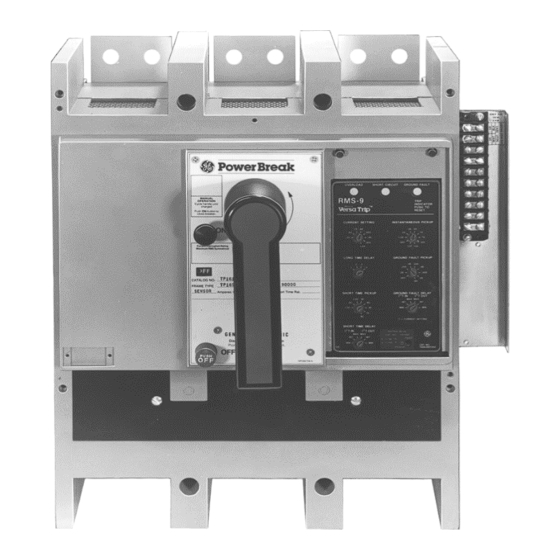
Page 9: Chapter 2. Breaker Operation
Circuit Breakers Chapter 2. Breaker Operation 2–1 Standard Features Power Break circuit breakers are equipped with the follow- ing standard features. The letters are keyed to the breaker illustrations in Figures 4, 5, and 6. A A A A Indicator –... -
Page 10: Operating Instructions For Manually Charged Breakers
Fully Charged Contacts may be closed Closed Discharged Contacts may be opened Table 3. Sequence of operations that may be performed with Power Break circuit breakers. Operating Instructions for Manually Operating Instructions for Electrically Charged Breakers Charged Breakers Charging the Mechanism Springs... -
Page 11: Wiring Notes
Power Break ® Circuit Breakers Chapter 2. Breaker Operation charge as soon as the breaker is opened, whether from a fault trip or from being intentionally opened. C C C C A A A A U U U U T T T T I I I I O O O O N N N N : : : : Do not wire breakers for both automatic charge and automatic close unless a bell alarm with overcurrent lockout is incorporated. -
Page 12: Application Notes
Power Break ® Circuit Breakers Chapter 2. Breaker Operation Application Notes 2 2 2 2 ..Change the settings by twisting the indicator switches to the desired values or multipliers. See GEH-4657 for • Size the control power source according to the definitions of MicroVersaTrip functions and GEH- information in Table 3. -
Page 13: Cover And Trip Unit Removed From The Breaker
Power Break ® Circuit Breakers Chapter 2. Breaker Operation All breakers provided with tap cards are shipped with both (100% of the current rating on the HIGH Sensor Amp breaker name plate) and (50–75% of the current rating on the breaker name plate). The Sensor Amp card is packed and supported on the breaker handle. -
Page 14: Wiring Diagram For Microversatrip And Microversatrip Rms-9 Trip Units With Ground Fault On A Top-Fed Four-Wire Load
Power Break ® Circuit Breakers Chapter 2. Breaker Operation • High short-time or H-function trip units may not be used in frames that are not wired for H function (special CTs). • Special trip units for AK breakers with the M (no instantaneous) function may not be used with Power Break breakers. -
Page 15: Magnetrip™ Trip Units
Power Break ® Circuit Breakers Chapter 2. Breaker Operation 3 3 3 3 ..Install the replacement trip unit as shown in Figure a a a a ..Align the holes in the bottom of the trip unit with the guide pins in the mounting plate. -
Page 16: Chapter 3. Accessories
800–2000 A frame Power Break® circuit breakers Breaker Cover Removal with MicroVersaTrip® trip units. These accessories may also be installed in 800–1600 A frame Power Break break- Manual Breaker ers with MagneTrip™ trip units, but the UL listing is voided. -
Page 17: Breaker Cover Reassembly
Power Break ® Circuit Breakers Chapter 3. Accessories Figure 18. 1600–2000 A frame electrically operated breaker. Figure 20. Wire ties on the accessory leads and mounting plate insulator. Electrically Operated Breakers 1 1 1 1 ..Verify that all connections are secure and the breaker is free of debris. -
Page 18: Shunt Trip Device
Power Break ® Circuit Breakers Chapter 3. Accessories 5 5 5 5 ..Position the charging handle at the home position (6 o’clock) on the outer cover. Align the outer cover- mounting screw holes with those on the inner cover and install the four cover-mounting screws. -
Page 19: Shunt Trip Installation
Power Break ® Circuit Breakers Chapter 3. Accessories Shunt Trip Installation N N N N O O O O T T T T E E E E : : : : If the shunt trip is being replaced because of a defective coil, the cause of the initial failure should first be determined. -
Page 20: Undervoltage Release Device
Power Break ® Circuit Breakers Chapter 3. Accessories 3–4 Undervoltage Release Device Catalog Voltage Continuous Dropping Number Rating Current, mA Resistor* The undervoltage release device (UVR), shown in Figure TPUV1S 120 Vac none 28, opens the circuit breaker when the supply voltage... -
Page 21: Blown-Fuse Trip Device
Power Break ® Circuit Breakers Chapter 3. Accessories Figure 33. Installing the UVR mounting screw. 1 1 1 1 3 3 3 3 ..Perform the following functional check of the UVR: Figure 31. Slide reset lever and spring on the mounting plate. -
Page 22: Blown-Fuse Trip Device Installation
Power Break ® Circuit Breakers Chapter 3. Accessories Each coil of the blown-fuse trip device is wired across a fuse so that the voltage across an open fuse is fed back to the accessory coil. When the coil is energized, the solenoid core releases the spring-biased latch, allowing the slide to rotate the breaker latch, tripping the breaker. -
Page 23: Auxiliary Switch Installation
Power Break ® Circuit Breakers Chapter 3. Accessories Figure 38. Trip unit removed from the breaker. Figure 37. Auxiliary switch wiring diagram. Catalog Number of Maximum Number Switch Elements Current Rating 6 A at 240 Vac TPAS2ABx 1–12 .25 A at 250 Vdc .50 A at 125 Vdc... -
Page 24: Remote Close Solenoid And Remote Charge Indication
Power Break ® Circuit Breakers Chapter 3. Accessories white leads. Verify an open circuit between the red and white leads. b b b b ..With the circuit breaker , the auxiliary switch contacts should change sense. -
Page 25: Padlock Function
Power Break ® Circuit Breakers Chapter 3. Accessories Padlock Function Handle Button Lock A standard feature on motor-operated breakers that pre- vents manual charging of the mechanism, as shown in Figure 5. OFF Button Padlock with Door Interlock This accessory prevents opening of the panel door when the breaker is . -
Page 26: Chapter 4. Maintenance
(Molykote G) or Mobil 28 grease. GE recommends the use of kerosene for removing hardened grease and dirt from the latch and bearing surfaces. All excess lubricant should be removed to avoid any contamination of dirt or dust. - Page 28 GE Industrial Systems General Electric Company 41 Woodford Ave., Plainville, CT 06062 GEH4693 R05 0998 © 1998 General Electric Company...