
Related Manuals for ABB OTAC-01


Summary of Contents for ABB OTAC-01
- Page 1 Drive Low Voltage AC Drives User’s Manual Pulse Encoder Interface Module OTAC-01 Phone: 800.894.0412 - Fax: 888.723.4773 - Web: www.clrwtr.com - Email: info@clrwtr.com...
-
Page 2: Safety
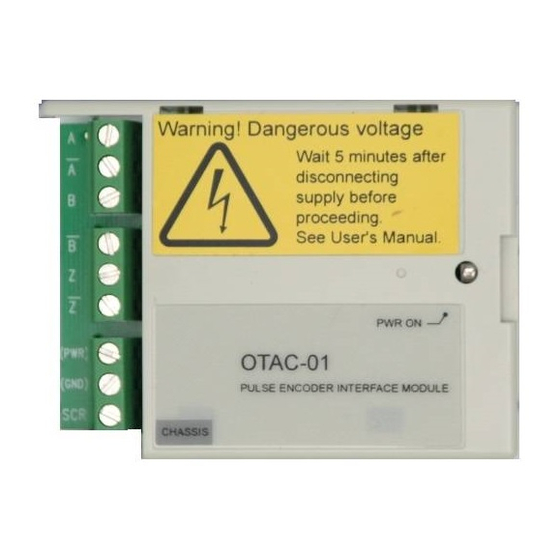
Safety WARNING! All electrical installation and maintenance work on the drive should be carried out by qualified electricians only. WARNING! The drive and adjoining equipment must be properly grounded. WARNING! Do not attempt any work on a powered drive. After switching off the mains, always allow the intermediate circuit capacitors 5 minutes to discharge before working on the drive, the motor or the motor cable. -
Page 3: Table Of Contents
Table of Contents Safety ............2 Use of Warnings and Notes . -
Page 4: Installation
Pass Through X0061 Compatibility The OTAC-01 module is compatible with all ACS550 drives. To confirm compatibility with a particular pulse encoder, compare the pulse encoders requirements to the “Specifications” on page 19. Installation Phone: 800.894.0412 - Fax: 888.723.4773 - Web: www.clrwtr.com - Email: info@clrwtr.com... -
Page 5: Installing The Module
Installing the Module Delivery Check The OTAC-01 module package contains: • OTAC-01 module • Warning stickers in several languages • This manual Mounting WARNING! Follow the safety instructions given in this guide and in the ACS550 User’s Manual. To mount the OTAC-01 module: 1. - Page 6 Wiring – General The pulse encoder should be connected to the OTAC-01 module with cables as specified below. 4 × (2+1) Twisted pair cable with individual Cable construction and overall shields.
- Page 7 Wiring – The Encoder Power The OTAC-01 module does not supply power for the encoder. An external power supply (as diagrammed below) is recommended. The drive’s 24 VDC supply from terminals X1:10 and X1:11 can be used if the total draw on the supply does not exceed 250 mA. Use the following table to determine if the drive’s supply can be used.
- Page 8 Note: Normally, ground the cable shield only at the drive end. However, if the encoder is isolated from the motor, and from ground, then connect the cable shields to both the OTAC module and the encoder housing. Note: Do not route the encoder cables parallel to power (e.g. motor) cables.
- Page 9 • Run the drive in the forward direction. • Verify that parameter 0147 is increasing in the positive MECH REVS direction. • If not, switch the A/A (or 1/1) connections. Encoder Output Types The following diagrams identify the typical encoder output types. Push-pull Open collector (Sinking) Open emitter (Sourcing) = Encoder input power supply voltage...
- Page 10 • Encoder A/1 and B/2 should be wired to OTAC terminals B and A respectively. • Encoder A/1 and B/2 (if present) should be wired to OTAC terminals B and A respectively. Differential connection OTAC-01 Encoder Module 0V V Encoder...
- Page 11 Diagram assumes normal pulse order in Forward rotation: Pulse 1 leads as diagrammed below For encoders with pulse B/2 leading, change diagram for these connections: Encoder A/1 and B/2 should be wired to OTAC terminals B and A respectively. OTAC-01 Module Encoder 0V V...
- Page 12 Diagram assumes normal pulse order in Forward rotation: Pulse 1 leads as diagramed below For encoders with pulse B/2 leading, change diagram for these connections: Encoder A/1 and B/2 should be wired to OTAC terminals B and A respectively. OTAC-01 Encoder Module Encoder...
-
Page 13: Start-Up
Start-Up Configuration To configure the operation of the OTAC-01 module: 1. Power up the drive. 2. Use the control panel on the drive and set the parameters described below. Operating Data The following parameters provide feedback from the encoder. The drive sets the parameter values based on measurements or calculations. - Page 14 MOTOR CTRL MODE – Drive uses feedback from an optional encoder. This function requires the Pulse ENABLE Encoder Interface Module (OTAC-01) and an encoder. Operation depends on the setting of parameter 9904 MOTOR CTRL MODE • 9904 = 1 (...
- Page 15 Group 50: Encoder Code Description Range Resolution Default 5011 POSITION RESET 0, 1 Resets the encoder’s position feedback. This parameter is self-clearing. – Inactive. DISABLE – Resets the encoder position feedback. Parameters reset depends on the state of ENABLE parameter 5010 Z PLS ENABLE •...
-
Page 16: Diagnostics
Diagnostics Diagnostic LED There is one diagnostic LED on the OTAC-01 module. If the OTAC-01 is properly installed, the green LED lights when the drive is powered up. If the LED does not light after power-up: Step down this column. - Page 17 • Encoder presence and proper connection (reverse wired, loose connection, or short circuit). • Voltage logic levels are outside of the specified range. • Pulse Encoder Interface Module, OTAC-01, presence and proper connection to the ACS550. 2024 ENCODER •...
-
Page 18: Technical Data
Technical Data Dimensions Module dimensions are: Ref. 14.5 0.57 77.8 3.06 58.8 2.31 X0063 Enclosure Degree of Protection The module is mounted inside the drive enclosure. Refer to the drive’s rating. Ambient Conditions The module is mounted inside the drive enclosure. Refer to the drive’s requirements. -
Page 19: Specifications
Specifications Module Specifications The OTAC-01 module: • Supports three channels: CH A, CH B, CH Z. • Includes pass-through terminals to connect an external power supply (required) to the pulse encoder. • All materials are UL-approved. Channel Specifications Channel specifications: •...