Table of Contents
Advertisement
Advertisement
Table of Contents

Related Manuals for Hitachi RCI-1.0FSN4


Summary of Contents for Hitachi RCI-1.0FSN4
-
Page 1: Service Manual
INDOOR UNITS SYSTEM FREE SERIES & COMPLEMENTARY SYSTEMS Service Manual RCI - FSN4 RCIM - FSN4(E) RCD - FSN3 RPC - FSN3(E) RPI - FSN(3/4)(P)E(-f) RPIM - FSN4E(-DU) RPK - FSN(H)3M RPF - FSN2E RPFI - FSN2E KPI - (E/X)4E DX - Interface - EXV-E2 Econofresh - EF-456NE... - Page 3 Contents C o n t e n t s General information Unit installation Piping work and refrigerant charge Electrical and control settings Control system Optional functions Commissioning Electrical check of main parts Servicing Troubleshooting Maintenance notes SMGB0099 rev.0 - 12/2016...
-
Page 5: Table Of Contents
1.3.13 Centralised remote controls ........................13 1.3.14 Building air conditioning controls ......................... 13 1.3.15 Gateways for building management systems (BMS) .................. 14 1.3.16 Control support devices ..........................14 1.3.17 Control accessories ............................. 15 1.3.18 Other devices compatible with HITACHI Air Conditioning systems ............. 15 Unit installation ......................17 2.1 RCI - 4-way cassette ..........................19 2.1.1 Accessories supplied with the unit ......................... 19 2.1.2 Unit installation .............................. 20 2.1.3 Air panel installation: P-N23NA2 ........................ - Page 6 General Index 2.3.4 Air panel installation ............................39 2.4 RPC - Ceiling............................41 2.4.1 Accessories supplied with the unit RPC-FSN3 ....................41 2.4.2 Unit installation .............................. 42 2.4.3 Suspension bracket installation RPC-FSN3E ....................42 2.4.4 Suspension for FSN3 units ..........................43 2.4.5 Indoor unit installation ........................... 45 2.5 RPI(M) - Ducted indoor unit (0.6-6.0)FSN4E(-DU)................48 2.5.1 Accessories supplied with the unit ......................... 48 2.5.2 Unit installation ..............................
- Page 7 General Index 2.12.3 Mounting method ............................76 2.12.4 Thermistor installation ..........................77 2.13 Optional accessories ..........................79 2.13.1 Outdoor air inlet ............................79 2.13.1.1 For RCI-FSN4 indoor units: OACI-160K2 and PD-75A ..............81 2.13.2 Duct adapters .............................. 83 2.13.2.1 For RCIM-FSN4(E) indoor units: PD-75C ..................83 2.13.2.2 For RCD-FSN3 indoor units: PD-150D ..................83 2.13.3 T-duct connection position ........................... 84 2.13.3.1 For RCI-FSN4 indoor units: TKCI-160k ..................
- Page 8 General Index 3.5.5 RPC-(1.5-6.0)FSN3E - Ceiling type ......................112 3.5.6 RPI-(0.6-1.5)FSN4E - Ducted indoor unit .....................116 3.5.7 RPI-(2.0-6.0)FSN4E - Ducted indoor unit .....................118 3.5.8 RPI-(8.0/10.0)FSN3E-(f) - Ducted indoor unit ..................... 120 3.5.9 RPI-(16.0/20.0)FSN3PE(-f) - Ducted indoor unit ..................121 3.5.10 RPIM-(0.6-1.5)FSN4E(-DU) - Ducted indoor unit ..................123 3.5.11 RPK-(0.6-4.0)FSN(H)3M - Wall type ......................125 3.5.12 RPF(I)-(1.0-2.5)FSN2E - Floor type ......................128 3.6 Refrigerant charge..........................129 3.7 Precautions in the event of refrigerant leaks ..................129 3.7.1 Maximum permissible concentration of hydrofluorocarbon (HFC) .............. 129 3.7.2 Calculation of the concentration of refrigerant .....................
- Page 9 General Index Control system ....................... 185 5.1 Printed circuit boards for RCI-FSN4 indoor units ................186 5.1.1 Printed circuit boards for RCI-(1.0-6.0)FSN4 ....................186 5.2 Printed circuit boards for RCIM-FSN4(E) indoor units ................ 187 5.3 Printed circuit boards for RCD-FSN3 indoor units................188 5.4 Printed circuit board for RPC-FSN3E, RPF(I), units................189 5.5 Printed circuit board for RPC-FSN3 ....................190 5.6 Printed circuit board for RPI(M)-(0.6-6.0)FSN4E ................191 5.7 Printed circuit board for RPI-(8.0-20.0)FSN3(P)E(-f) units ..............192 5.8 Printed circuit board for RPK-FSN(H)3M units ..................193 5.8.1 For RPK-(0.6-1.5)FSN(H)3M ........................
- Page 10 General Index 7.1.3 PC-ARFPE remote control .......................... 235 7.2 Test procedure using the wireless remote control ................237 7.2.1 PC-AWR wireless remote control ........................ 237 7.3 Test run check list ..........................238 Electrical check of main parts ................239 8.1 Thermistor ............................240 8.2 Electronic expansion valve ........................240 8.3 Automatic louver mechanism ......................241 8.3.1 RCI indoor units ............................241 8.3.2 RCIM indoor units ............................
- Page 11 General Index 9.2.12 Removal of the inlet air thermistor ......................266 9.2.13 Removal of the automatic louver motor ..................... 267 9.3 RCD-(0.8-6.0)FSN3 - 2-way cassette ....................268 9.3.1 Removal of the Air filter and the Air inlet grille ..................... 268 9.3.2 Removal of the electrical box ........................268 9.3.3 Removal of the optional air panel ........................ 269 9.3.4 Removal of the fan duct and the fan ......................269 9.3.5 Removal of the printed circuit board (PCB) ....................271 9.3.6 Removal of the float switch ......................... 272 9.3.7 Removal of the drain mechanism ........................ 272 9.3.8 Removal of the drain pan ..........................
- Page 12 General Index 9.6.6 Removal of the float switch ......................... 294 9.6.7 Removal of the air filter ..........................294 9.7 RPI-(8.0-20.0)FSN3(P)E(-f) - Ducted indoor unit ................295 9.7.1 Removal of the electrical box cover ......................295 9.7.2 Removal of electrical components ......................295 9.7.3 Removal of the inlet and outlet air thermistors .................... 295 9.7.4 Removal of the thermistors from the liquid and gas pipes ................297 9.7.5 Removal of the drain pan ..........................297 9.7.6 Fan removal ..............................298 9.7.7 Removal of the float switch ......................... 301 9.7.8 Removal of the air filter ..........................
- Page 13 General Index 9.11.1 System description ............................ 335 9.11.2 Structure and part names .......................... 335 9.11.3 Service cover location ..........................335 9.11.4 Removal of Heat Exchanger ........................336 9.11.5 Removal of the air filter ..........................336 9.11.6 Removal of the float switch (X4E series only) ................... 337 9.11.7 Removal of the damper motor ........................338 9.11.8 Removal of the electrical box ........................339 9.11.9 Removal of the PCB ..........................339 9.11.10 Removal of the fan motor ........................340 9.11.11 Removal of the DX-Coil Module (X4E series only) ..................
-
Page 15: General Information
1.3.10 Multi-Kits ...............................11 1.3.11 Individual remote controls ..........................12 1.3.12 Receiver kit for combination with wireless remote control switch ..............12 1.3.13 Centralised remote controls ........................13 1.3.14 Building air conditioning controls ......................... 13 1.3.15 Gateways for building management systems (BMS) .................. 14 1.3.16 Control support devices ..........................14 1.3.17 Control accessories ............................. 15 1.3.18 Other devices compatible with HITACHI Air Conditioning systems ............. 15 SMGB0099 rev.0 - 12/2016... -
Page 16: General Information
1 General information General information 1.1 General information ©Copyright 2016 Johnson Controls-Hitachi Air Conditioning Spain, S.A.U. - All rights reserved. No part of this publication may be reproduced, copied, filmed or transmitted in any shape or form without the permission of Johnson Controls-Hitachi Air Conditioning Spain, S.A.U. Within the policy of continuous improvement of its products, Johnson Controls-Hitachi Air Conditioning Spain, S.A.U. reserves the right to make changes at any time without prior notification and without being compelled to introduce them into products subsequently sold. This document may therefore have been subject to amendments during the life of the product. HITACHI makes every effort to offer correct, up-to-date documentation. Despite this, printing errors cannot be controlled by HITACHI and are not its responsibility. As a result, some of the images or data used to illustrate this document may not refer to specific models. No claims will be accepted based on the data, illustrations and descriptions included in this manual. No type of modification must be made to the equipment without prior, written authorization from the manufacturer. 1.1.1 Introduction HITACHI offers the SYSTEM FREE range of indoor units, the main advantage of which is that they can be combined with UTOPIA and SET-FREE series outdoor units. This eliminates the need to duplicate models of indoor units and reduces stock. SYSTEM FREE Complementary systems Line up of Indoor Units RCI-FSN4 RCIM-FSN4(E) RCD-FSN3 RPC-FSN3 KPI-(E/X)4E RPC-FSN3E... -
Page 17: Applied Symbols
1 General information Applied symbols 1.2 Applied symbols During normal air conditioning system design work or unit installation, greater attention must be paid in certain situations requiring particular care in order to avoid damage to the unit, the installation or the building or property. Situations that jeopardise the safety of those in the surrounding area or that put the unit itself at risk will be clearly indicated in this manual. To indicate these situations, a series of special symbols will be used to clearly identify these situations. Pay close attention to these symbols and to the messages following them, as your safety and that of others depends on D A N G E R • The text following this symbol contains information and instructions relating directly to your safety and physical wellbeing. • Not taking these instructions into account could lead to serious, very serious or even fatal injuries to you and others in the proximities of the unit. -
Page 18: Product Classification And Line-Up
1 General information Product classification and line-up 1.3 Product classification and line-up 1.3.1 Classification of indoor unit models Unit type (indoor unit): RCI, RCIM, RCD, RPC, RPI, RPIM, RPK, RPF, RPFI Position-separating hyphen (fixed) Capacity (HP): 0.6, 0.8, 1.0, 1.5, 2.0, 2.5, 3.0, 4.0, 5.0, 6.0, 8.0, 10.0, 16.0, 20.0 FS = SYSTEM FREE N = R410A refrigerant H = Hotel (RPK-(0.6-1.5) only) 2/3/4 = series P= Pair E = Made in Europe M = Made in Malaysia – = Made in Japan or China (-DU) = Drain Up (RPIM only) (-f) = Non-flammable insulation (RPI-(8.0-20.0)FSN3E-f only – (-xx) 1.3.2 Classification of KPI models KPI- Ventilation system Position-separating hyphen (fixed) Capacity (m /h): 250, 500, 800, 1000, 1500, 2000 2 = 1 ~ 230V 50Hz E = Energy recovery X = Active (Energy recovery + DX section) 4 = series... -
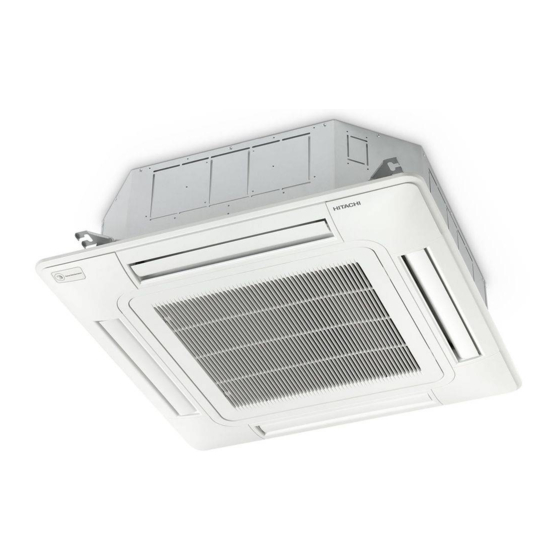
Page 19: Product Line-Up: Indoor Units
Check the exact classification for each unit (model, type, power and series) in “1.3.1 Classification of indoor unit models”. RCI and RCIM indoor units RCIM 4-way cassette 4-way cassette (compact) Unit Code Unit Code RCIM-0.6FSN4(E) (*) 60278215 (7E411137) RCIM-0.8FSN4(E) 60278216 (7E411100) RCI-1.0FSN4 70405001 RCIM-1.0FSN4(E) 60278217 (7E411101) RCI-1.5FSN4 70405002 RCIM-1.5FSN4(E) 60278218 (7E411102) RCI-2.0FSN4 70405003 RCIM-2.0FSN4(E) (**) 60278219 (7E411103) RCI-2.5FSN4 70405004 RCIM-2.5FSN4(E) (**) 60278220 (7E411104) RCI-3.0FSN4... - Page 20 1 General information Product classification and line-up RCD and RPC indoor units 2-way cassette Ceiling type Unit Code Unit Code Unit Code Unit Code RCD-0.8FSN3 (*) 60278242 RCD-1.0FSN3 (*) 60278243 RCD-1.5FSN3 (*) 60278244 RPC-1.5FSN3 60278164 RCD-2.0FSN3 (*) 60278245 RPC-2.0FSN3 60278165 RCD-2.5FSN3 (*) 60278246 RPC-2.5FSN3 60278166 RCD-3.0FSN3 (*) 60278247 RPC-3.0FSN3E 7E443005 RPC-3.0FSN3 60278167 RCD-4.0FSN3 (*)
- Page 21 1 General information Product classification and line-up RPI and RPIM indoor units RPIM Indoor ducted unit Indoor ducted unit (compact) Unit Code Unit Code Unit Code RPIM-0.6FSN4E (*) 7E430037 RPI-0.6FSN4E (*) 7E424037 RPIM-0.6FSN4E-DU (*) 7E431037 RPIM-0.8FSN4E 7E430013 RPI-0.8FSN4E 7E424013 RPIM-0.8FSN4E -DU 7E431013 RPIM-1.0FSN4E 7E430014 RPI-1.0FSN4E 7E424014 RPIM-1.0FSN4E -DU 7E431014 RPIM-1.5FSN4E 7E430015 RPI-1.5FSN4E 7E424015...
- Page 22 1 General information Product classification and line-up RPK, RPF and RPFI indoor units RPFI Wall type Floor type Floor concealed type Unit Code Unit Code Unit Code RPK-0.6FSN3M (*) 60278145 RPK-0.6FSNH3M (*) 60278153 RPK-0.8FSN3M 60278146 RPK-0.8FSNH3M 60278154 RPK-1.0FSN3M 60278147 RPK-1.0FSNH3M 60278155 RPF-1.0FSN2E 7E450001 RPFI-1.0FSN2E 7E460001 RPK-1.5FSN3M 60278148 RPK-1.5FSNH3M 60278156 RPF-1.5FSN2E...
-
Page 23: Product Line-Up: Kpi Energy Recovery Unit
1 General information Product classification and line-up 1.3.6 Product line-up: KPI energy recovery unit Energy recovery Active (Energy Recovery+DX section) Unit Code Unit Code KPI-252E4E 70603000 KPI-502E4E 70603001 KPI-502X4E 70603201 KPI-802E4E 70603002 KPI-802X4E 70603202 KPI-1002E4E 70603003 KPI-1002X4E 70603203 KPI-1502E4E 70603004 KPI-2002E4E 70603005 1.3.7 Product line-up: DX-Interface DX-Interface Unit Code EXV-2.0E2... -
Page 24: Accessory Code List
1 General information Product classification and line-up 1.3.9 Accessory code list HITACHI has a wide range of accessories and remote control systems that can be used with the SET FREE and UTOPIA outdoor units. Consult the Technical Catalogue for controls and for the corresponding outdoor units. Name Unit Reference Description Code Figure PD-75A RCI-FSN4 60291763 PD-75C RCIM-FSN4(E) Duct adapter 60292014 for fresh outdoor air intake kit PD-150D RCD-FSN3 60292064 OACI-160K2 RCI-FSN4 Fresh outdoor air intake kit 60291761 T-shaped duct connection kit TKCI-160K RCI-FSN4 60291762 for fresh outdoor air intake ki PDF-71C1 RCI-(1.0-2.5)FSN4 60299436 Duct connecting flange for... -
Page 25: Multi-Kits
1 General information Product classification and line-up Name Unit Reference Description Code Figure DUPC-63K1 60291935 DUPC-71K1 RPC-FSN3 Drain-up Mechanism 60291936 DUPC-160K1 60291937 PS-MSK2 RCI-FSN4 70590903 SOR-NEP RPC-FSN3 60291825 Motion sensor kit SOR-NEC RCIM-FSN4(E) 60292011 SOR-NED RCD-FSN3 60292055 SLT-30-200-L600 70550200 SLT-30-250-L600 70550201 Noise damper SLT-30-300-L600 70550202 SLT-30-355-L600 70550203 HEF-252 70552201... -
Page 26: Individual Remote Controls
1 General information Product classification and line-up 1.3.11 Individual remote controls Name Description Code Figure PC-ARFPE Remote control with timer 70510002 PC-ARH Simplified remote control 60291486 PC-AWR Wireless remote control 60291056 1.3.12 Receiver kit for combination with wireless remote control switch Compatible Wireless Receiver kit name Indoor Unit application Code Figure remote control... -
Page 27: Centralised Remote Controls
1 General information Product classification and line-up 1.3.13 Centralised remote controls Name Description Code Figure PSC-A64GT Touch screen central station 60291730 PSC-A32MN Touch screen central station mini 60291966 PSC-A64S Centralised remote control 60291479 PSC-A16RS Centralised ON/OFF control 60291484 1.3.14 Building air conditioning controls Name Description Code Figure CSNET WEB Centralised control system which runs CSNET WEB software 7E512000 (PSC-A160WEB1) to control the indoor units Centralised control with a touch interface of 12 inches which CSNET Manager LT 7E512201... -
Page 28: Gateways For Building Management Systems (Bms)
1 General information Product classification and line-up 1.3.15 Gateways for building management systems (BMS) Name Description Code Figure Integration with installation with intelligent control (Building HC-A8MB Management System) Gateway Interface to MODBUS 7E513204 systems (Max. 8 indoor units). Integration with installation with intelligent control (Building HC-A64MB Management System) Gateway Interface to MODBUS 7E513205 systems (Max. 64 indoor units). Integration with installations with intelligent control (BMS). HC-A16KNX 7E513300 Gateway Interface to KNX systems. Integration with installations with intelligent control (BMS) KNX001 7E5121000 through CSNET WEB. Gateway Interface to KNX systems. Integration with installation with intelligent control (Building Management System) Gateway Interface to LONWORKS HARC-BX E (A) 60290874 systems. (H-LINK I communication) (Max. 64 units with 8 parameters) Integration with installation with intelligent control (Building Management System) Gateway Interface to LONWORKS HARC-BX E (B) 60290875... -
Page 29: Control Accessories
2P-Extension cord (10 metres) 7E790211 PRC-15E1 2P-Extension cord (15 metres) 7E790212 PRC-20E1 2P-Extension cord (20 metres) 7E790213 PRC-30E1 2P-Extension cord (30 metres) 7E790214 Net Configuration Kit Net configuration kit for HC-A(8/64)MB and HC-A64NET 7E512306 1.3.18 Other devices compatible with HITACHI Air Conditioning systems In addition to all the aforementioned HITACHI controls, there are some non-HITACHI devices for combination with HITACHI Air Conditioning systems. These are the following: • HITACHI-AIRZONE gateway (HTI11001): Applicable to HITACHI RPI(M) units providing compatibility with the AIRZONE systems, zone-based climate-control systems. • Power meter: Siemens power meter for CSNET WEB and CSNET Manager. • MODBUS-BACNET gateway: Solution offered by Intesis Software company which transfers MODBUS data into BACNET data. • MODBUS-FIDELIO gateway: Solution offered by Intesis Software company which transfers MODBUS data into FIDELIO data. SMGB0099 rev.0 - 12/2016... -
Page 31: Unit Installation
2 Unit installation U n i t i n s t a l l a t i o n Index RCI - 4-way cassette ..........................19 2.1.1 Accessories supplied with the unit ......................... 19 2.1.2 Unit installation .............................. 20 2.1.3 Air panel installation: P-N23NA2 ........................22 2.1.4 Accessories supplied with the air panel P-N23NA2 .................. - Page 32 2 Unit installation 2.8.2 Unit installation .............................. 58 2.8.3 Mounting bracket dimensions ........................62 RPF - Floor type, RPFI - Floor concealed type ..................64 2.9.1 Accessories supplied with the unit ......................... 64 2.9.2 Unit installation .............................. 64 2.9.3 Change in the air outlet direction (RPFI units) ....................66 2.9.4 RPF: Optional PC-ARFPE remote control location ..................
-
Page 33: Rci - 4-Way Cassette
2.1.1 Accessories supplied with the unit Check that the following accessories are supplied with the unit. N O T E Please contact your HITACHI distributor if any of the accessories has not been supplied with the unit. RCI-FSN4 indoor unit... -
Page 34: Unit Installation
2 Unit installation RCI - 4-way cassette 2.1.2 Unit installation Initial checks Install the indoor unit with a proper clearance around it paying careful attention of installation direction for the piping, wiring and maintenance working space, as shown below. Provide a service access door near the unit piping connection area on the ceiling. -
Page 35: Mounting Of Indoor Unit
2 Unit installation RCI - 4-way cassette Mounting of suspension bolts Mount suspension bolts using M10 (W3/8) as size, as shown. For concrete slab: For steel beam: Insert 150 to 160mm (100 to 150Kg) Concrete I-Beam Suspension Bolt Steel (w3/8 or M10) Anchor Bolt (W3/8 or M10) ... -
Page 36: Air Panel Installation: P-N23Na2
2 Unit installation RCI - 4-way cassette For ceiling already completed with panels Attach this side of the Attach this side of the checking checking pattern to the lower pattern to the inner side of the side of the unit opening of the ceiling Indoor unit Indoor... - Page 37 2 Unit installation RCI - 4-way cassette N O T E Perform the attaching work in the reverse procedure of removing for install the air intake grille. The air inlet grille can be attached from any 4 directions by rotating it. The air intake grille direction can be selected freely. ...
- Page 38 2 Unit installation RCI - 4-way cassette C A U T I O N • If tighten long screws insufficient, may cause something wrong as below. Air Leakage Smudge Dewing • If any gap has even though tighten long screws sufficient, readjust the height of indoor unit. No gap shall exist •...
- Page 39 2 Unit installation RCI - 4-way cassette Attachment of corner pocket cover with motion sensor PS-MSK2 on the air panel model P-N23NA2 The corner pocket cover with motion sensor can be attached to any of corners. Determine the attaching place as user’s request.
-
Page 40: Accessories Supplied With The Air Panel P-N23Na2
2.1.4 Accessories supplied with the air panel P-N23NA2 Check that the following accessories are supplied with the unit. N O T E Please contact your HITACHI distributor if any of the accessories has not been supplied with the unit. Accessory Appearance... -
Page 41: Rcim - 4-Way Cassette (Compact)
For Fitting Paper Pattern Cross Recessed Head Screws (M5) For Fitting Paper Pattern • Contact your HITACHI distributor if any of the accessories have not been supplied with the unit. Cross Recessed Head Screws (M5) For Fitting Paper Pattern Head Screws (M5) •... -
Page 42: Unit Installation
2 Unit installation RCIM - 4-way cassette (compact) 2.2.2 Unit installation Initial checks Check that there is enough space between the false ceiling and the Clearance: Min. 30 mm ceiling of the room to house the unit. Its height must be less than the measured distance. - Page 43 2 Unit installation RCIM - 4-way cassette (compact) Installation Cut the area of the unit in the false ceiling and reinforce the opening made. Install the M10 (3/8”) suspension bolts depending on the type of surface: Concrete beams Dimension of opening: 580 (576~590) Unit size: 570 1 150 to 160 mm...
-
Page 44: Accessories Supplied With The Air Panel: P-Ap56Nam
2.2.3 Accessories supplied with the air panel: P-AP56NAM Check that the following accessories are supplied with the unit. N O T E Please contact your HITACHI distributor if any of the accessories has not been supplied with the unit. Accessory Appearance... -
Page 45: Air Panel Installation
2 Unit installation RCIM - 4-way cassette (compact) 2.2.4 Air panel installation C A U T I O N Take care while the air panel is unpacked and protect it by placing it on insulating or soft material so as not to scratch the sealant insulation. N O T E •... - Page 46 2 Unit installation RCIM - 4-way cassette (compact) Nº Part Indoor unit Refrigerant pipe connections Electrical box Fixing plate (Indoor unit) Indication “PIPE SIDE” Air panel Long screw (4) Mounting sheet Fit the air panel in the attachment position using the screws supplied (M5).
- Page 47 2 Unit installation RCIM - 4-way cassette (compact) b. Insert the fixing hooks (2 portions) at A to the air panel and insert the fixing hook (1 portion) at B to the air panel. N O T E • Catch securely the strap onto the projection. If not, the comer pocket cover may fall down when removing it so that may cause injury.
- Page 48 2 Unit installation RCIM - 4-way cassette (compact) Electrical connection of the air panel C A U T I O N • Perform securely the electrical wiring work. If the electrical work is not completed, heat generation at the connection, a fire or an electric shock may occur.
-
Page 49: Rcd - 2-Way Cassette
2.3.1 Accessories supplied with the unit Check that the following accessories are supplied with the unit. N O T E Please contact your HITACHI distributor if any of the accessories has not been supplied with the unit. Accessory Appearance Quantity... -
Page 50: Unit Installation
2 Unit installation RCD - 2-way cassette 2.3.2 Unit installation Initial checks Check that there is enough space between the false ceiling and the (mm) ceiling of the room to house the unit. Its height must be less than Indoor unit the measured distance. - Page 51 2 Unit installation RCD - 2-way cassette Steel beams Wooden beams Concrete beams Wooden bar (60 mm to 90 mm square) Steel beam 1 150 to 160 mm Anchor bolt 2 Steel Wooden beam (W3/8 or M10) 3 Anchor bolt (W3/8 or M10) 4 Concrete 5 Insert (100 to 150 kg) 1 Suspension bolts (field-supplied)
- Page 52 2 Unit installation RCD - 2-way cassette Check that the condensate discharge system in the indoor Drain pipe unit works correctly. To do so, check the level of the drain pan using a spirit level or a clear flexible pipe full of water. The side of the unit on which the drain hose is located must be around 5 mm lower than the other sides.
-
Page 53: Accessories Supplied With The Air Panel: P-N23Dwa / P-N46Dwa
2.3.3 Accessories supplied with the air panel: P-N23DWA / P-N46DWA Check that the following accessories are supplied with the unit. N O T E Please contact your HITACHI distributor if any of the accessories has not been supplied with the unit. Accessory Appearance... - Page 54 2 Unit installation RCD - 2-way cassette C A U T I O N Indoor unit • To avoid damaging the panel, the long screws securing it are fitted with stops to stop tightening at the set position. • Where the air panel does not reach the ceiling surface or in the event of air P-N46DWA leaks on the touching surface, readjust the installation height of the indoor unit.
-
Page 55: Rpc - Ceiling
2.4.1 Accessories supplied with the unit RPC-FSN3 Check that the following accessories are supplied with the unit. N O T E Please contact your HITACHI distributor if any of the accessories has not been supplied with the unit. Accessory Appearance... -
Page 56: Unit Installation
2 Unit installation RPC - Ceiling 2.4.2 Unit installation Initial checks Check that there is enough space around the unit. Consult the corresponding chapter of the Technical Catalogue for information on the unit measurements. Before starting installation, plan the direction of the pipes and wiring required. Also bear in mind that there must be enough space around the unit for installation and maintenance. -
Page 57: Suspension For Fsn3 Units
2 Unit installation RPC - Ceiling The suspension bracket can be hung in two positions: Unit: mm Model RPC-2.0 1314 1140 1230 RPC-2.5 RPC-3.0 1314 1140 1230 RPC-4.0 RPC-5.0 1574 1400 1490 RPC-6.0 Select the suspension bracket system in line with installation requirements. N O T E Installation position (a) is recommended for a partially hidden installation. - Page 58 2 Unit installation RPC - Ceiling 4 Pattern Board for Installation. The pattern board for the installation is printed on the packing. When making holes in wall and ceiling, the pattern board which hole positions for suspension, refrigerant pipe and drain pipe Upper cap are printed shall be used.
-
Page 59: Indoor Unit Installation
2 Unit installation RPC - Ceiling 8 When the indoor unit is mounted, create down-slope toward drain pipe connection to be well drainage. The figure shows the right drain pipe connection. (Before shipment) For the left drain pipe connection, create down-slope toward left. View from front (Drain pipe connection) View from right Lower the indoor unit 10mm when the optional drain-up mechanism is installed. - Page 60 2 Unit installation RPC - Ceiling Suspended unit installation C A U T I O N • Before lifting the unit, prepare any necessary means (ladders, scaffolding, elevator platform, etc.) and check that the current safety regulations in the place where the installation is taking place are met. Fix the unit with four M10 nuts •...
- Page 61 2 Unit installation RPC - Ceiling Continue for all installation types: Check that the condensate discharge system in the indoor unit works correctly. To do so, check the level of the drain pan using a spirit level or a clear flexible pipe full of water. The rear of the unit where the drain hose is located must be around 3 mm lower than the front side. Secure the drain hose with the clamp and adhesive supplied.
-
Page 62: Rpi(M) - Ducted Indoor Unit (0.6-6.0)Fsn4E(-Du)
2.5.1 Accessories supplied with the unit Check that the following accessories are supplied with the unit. N O T E Please contact your HITACHI distributor if any of the accessories has not been supplied with the unit. Accessory Appearance Quantity Purpose For the drain hose connection. - Page 63 2 Unit installation RPI(M) - Ducted indoor unit (0.6-6.0)FSN4E(-DU) Before starting installation, plan the direction of the pipes and wiring required. Also bear in mind that there must be enough space around the unit for installation and maintenance. Check that the ceiling surface where the unit is to be installed is completely horizontal. Check that the drain hose can be installed maintaining the necessary down-slope.
-
Page 64: Air Duct Connection
2 Unit installation RPI(M) - Ducted indoor unit (0.6-6.0)FSN4E(-DU) Once adjusted, tighten the suspension bracket nuts. Apply a thread-locking product to the bolts and nuts to prevent them from loosening. Otherwise, abnormal noise may be caused by mechanical vibrations and the indoor unit may become loose. Apply protective paint to the bolts and nuts to prevent rusting. -
Page 65: Maintenance Of The Suction Air Filter
2 Unit installation RPI(M) - Ducted indoor unit (0.6-6.0)FSN4E(-DU) 2.5.4 Maintenance of the suction air filter Simply remove the set screws from the bar -1- (RPIM units: 2 screws, RPI units: 3 screws) and remove it to pull the filter downwards. RPIM Change in the air suction direction RPIM-(0.6-1.5)FSN4E (-DU) Change in position of the air inlet on RPIM-(0.6-1.5)FSN4E(-DU) models: the position of the air inlet and, therefore, its direction can be modified by changing the position of the rear cover, as shown in the illustrations. - Page 66 2 Unit installation RPI(M) - Ducted indoor unit (0.6-6.0)FSN4E(-DU) RPI-(2.0-6.0)FSN4E Change in position of the air inlet on RPI-(2.0-6.0)FSN4E models: the position of the air inlet and, therefore, its direction can be modified by changing the position of the rear cover, as shown in the illustrations. 1 Initial position -A- of the air inlet (factory-supplied). 2 Air inlet and bottom cover away from the unit.
-
Page 67: Rpi - Ducted Indoor Unit (8/10)Fsn3E(-F)
2.6.1 Accessories supplied with the unit Check that the following accessories are supplied with the unit. N O T E Please contact your HITACHI distributor if any of the accessories has not been supplied with the unit. Accessory Appearance Quantity... - Page 68 2 Unit installation RPI - Ducted indoor unit (8/10)FSN3E(-f) Installation Install the M10 (3/8) suspension bolts depending on the type of surface: Steel beams Wooden beams Concrete beams Wooden bar (60mm to 90mm square) Steel beam Anchor bolt 1 150 to 160 mm (W3/8 or M10) Wooden beam 2 Steel...
-
Page 69: Air Duct Connection
2 Unit installation RPI - Ducted indoor unit (8/10)FSN3E(-f) 2.6.3 Air duct connection N O T E • Use field-supplied flexible ducts to avoid abnormal acoustic vibrations. • RPI units are supplied with a standard air filter on the suction side. This filter is supplied for cases where no suction duct is applied (or when the duct is very short). -
Page 70: Rpi - Ducted Indoor Unit (16/20)Fsn3Pe(-F)
2 Unit installation RPI - Ducted indoor unit (16/20)FSN3PE(-f) 2.7 RPI - Ducted indoor unit (16/20)FSN3PE(-f) 2.7.1 Unit installation Initial checks Install the indoor unit with a proper clearance around it paying careful attention of installation direction for the piping, wiring and maintenance working space, as shown below. - Page 71 2 Unit installation RPI - Ducted indoor unit (16/20)FSN3PE(-f) Drain Pan Level Front View Check to ensure that the foundation is flat, taking into account the maximum foundation gradient. The unit should be installed so that the Drain Pan side of the unit is slightly (approximately 5 mm) lower than the opposite side, in order to avoid the incorrect position of the drain discharge.
-
Page 72: Rpk - Fsn(H)3M Wall Mounted
2.8.1 Accessories supplied with the unit Check that the following accessories are supplied with the unit. N O T E Please contact your HITACHI distributor if any of the accessories has not been supplied with the unit. Q’ty Accessory Purpose 0.8-1.0... - Page 73 2 Unit installation RPK - FSN(H)3M Wall mounted Installation C A U T I O N • Where the mounting bracket must be installed on a wooden or concrete wall, make sure it is resistant enough to withstand a weight of 200 kg.
- Page 74 2 Unit installation RPK - FSN(H)3M Wall mounted Lift the unit carefully. Hang the indoor unit on the mounting bracket, keeping it vertical. Secure the bottom cover and the mounting bracket with three screws. C A U T I O N Make sure the unit is hanging correctly on the mounting bracket.
- Page 75 2 Unit installation RPK - FSN(H)3M Wall mounted Removal of the front panel for RPK-(2.0-4.0)FSN3M Hold both sides of flat panel and open it fully. Lift up the air filter, detach the catches from the indoor unit and remove the air filter downward. After the right arm shaft is pushed inward and the shafts are removed from the front panel, pull the flat panel frontward while the right arm shaft is slightly pushed inward. Remove this part Push the shaft from the hole. toward arrow direction. Flat panel ...
-
Page 76: Mounting Bracket Dimensions
2 Unit installation RPK - FSN(H)3M Wall mounted 2.8.3 Mounting bracket dimensions RPK-(0.6-1.5)FSN(H)3M unit suspension bracket Exterior contour for indoor unit Min. Min. Right side of Left side of service space service space 20 36 32 32 Suspension bracket (*1) (*1) Ø... - Page 77 2 Unit installation RPK - FSN(H)3M Wall mounted RPK-(2.0-4.0)FSN3M unit suspension bracket Exterior contour for indoor unit Left side of Min. Min. Right side of service space service space × × × Suspension bracket φ80 φ80 Left rear side hole for pipes Right rear side hole for and wirings pipes and wirings...
-
Page 78: Rpf - Floor Type, Rpfi - Floor Concealed Type
2.9.1 Accessories supplied with the unit Check that the following accessories are supplied with the unit. N O T E Please contact your HITACHI distributor if any of the accessories has not been supplied with the unit. Accessory Appearance Quantity... - Page 79 2 Unit installation RPF - Floor type, RPFI - Floor concealed type Install a service hatch near the pipe connection area and electrical junction box for installation and maintenance work. Unit (inside) Floor Service Service access panel access panel A (mm) B (mm) Model RPFI...
-
Page 80: Change In The Air Outlet Direction (Rpfi Units)
2 Unit installation RPF - Floor type, RPFI - Floor concealed type Side cover Front cover Fixing bolt RPF units: carry out the above operation after removing the front and side covers of the unit. Fixing bolt Adjustment bolt for installation (accessories) Fixing screws RPFI unit: install the optional air outlet grille as indicated... -
Page 81: Kpi Energy And Kpi Active Unit
2.10.1 Accessories supplied with the unit Check that the following accessories are supplied with the unit. N O T E Please contact your HITACHI distributor if any of the accessories has not been supplied with the unit. Accesory Appearance Quantity... - Page 82 2 Unit installation KPI energy and KPI active unit KPI-(252-2002)E4E energy recovery unit KPI-(502-1002)X4E active unit (mm) Check that there is enough space around the unit. Consult the corresponding chapter of the Technical Catalogue for information on the unit measurements. Before starting installation, plan the direction of the pipes and wiring required.
- Page 83 2 Unit installation KPI energy and KPI active unit Prepare the sling bolts. Fit the anchor bolts on the suspension bracket and adjust to ensure the unit is installed horizontally. Thread on the nuts and fit the washers for all the bolts, as shown in the figure. Fit two suspension brackets onto the nut and washer of each bolt, starting on one side. Check that the nuts and washers are correctly secured with the suspension bracket retainers and fit the brackets onto ...
-
Page 84: Duct Connection
2 Unit installation KPI energy and KPI active unit 2.10.3 Duct connection N O T E • Use field-supplied flexible ducts to avoid abnormal acoustic vibrations. • The unit is fitted with a pre-drilled hose to connect the supply duct. Check that there is no dust, sawdust or other foreign particles inside the ducts before connecting them. - Page 85 2 Unit installation KPI energy and KPI active unit Example of installation: Nº Name EA (exhaust air outlet) OA (outside air intake) Return air grille Supply air grille Service space Service access panel Example of installation: Deep hood Anchor bolt (to prevent rainwater from seeping in) (to the provided by user) (outdoor air intake)
-
Page 86: Econofresh Kit
2 Unit installation Econofresh Kit 2.11 Econofresh Kit 2.11.1 Accessories supplied with the unit Check to ensure that the following accessories are packed with the unit. N O T E If any of these accessories are not packed with the unit, contact your contractor. Accessory Cord AS Outdoor Thermistor (8m) -
Page 87: Mounting The Unit
2 Unit installation Econofresh Kit 2.11.3 Mounting the unit Step 1 Select a final location and installation direction of the unit paying careful attention to the space for wiring and maintenance. Step 2 Mount suspension bolts, as shown on the figure beside. Installation dimensions are shown on Dimensional Drawing. Wooden Bar For Concrete Slab (60 mm to 90 mm 150~160mm Square) Square Concrete washers Nuts I-Beam Wooden... -
Page 88: Example Of Installation
2 Unit installation Econofresh Kit 2.11.4 Example of installation 1 Ducting Connection Pre-drilled duct flanges are provided at the supply, return and outdoor air intake connections. It is recommended that a flexible duct connection be installed to minimize sound and vibration transmission. 2 Insulation All ducts should be insulated Especially the outdoor air duct, through which the cold outdoor air flows in, must be sufficiently insulated. The lowest temperature of the entering outdoor air flowing through the outdoor air duct is the lowest temperature for heating operation at the installation site. Return Air Filter Outdoor Air Duct Econofresh Supply Air Duct RPI Unit (Fully Insulated) (Field-Supplied) -
Page 89: Dx-Interface
2.12.1 Accessories supplied with the unit Check that the following accessories are supplied with the unit. N O T E Please contact your HITACHI distributor if any of the accessories has not been supplied with the unit. Accessory Appearance Purpose... -
Page 90: Mounting Method
2 Unit installation DX-Interface 4 Secure proper space around the control box and expansion valve box for operation and maintenance work. Also a service access door should be prepared in order to remove the DX-interface without getting rid of the ceiling plate. 5 Select a suitable and convenient location for the refrigerant piping connection. -
Page 91: Thermistor Installation
2 Unit installation DX-Interface 2.12.4 Thermistor installation Liquid and gas pipes thermistor Two type thermistors are supplied inside the control box. The purpose and identification of each one is as follow: PCB socket / Item PCB socket number Thermistor length (mm) Thermistor connector colour Liquid pipe thermistor Black THM 3 Gas pipe thermistor Yellow THM 5 C A U T I O N In case that the thermistors supplied with the Dx-Interface are not long enough, please make sure that the length extension is properly done avoiding the sensing distortion and that the joint is properly insulated to avoid any electrical failure. -
Page 92: Typical Installation
2 Unit installation DX-Interface Air thermistor Two air thermistors are supplied inside the control box. The purpose and identification of each one is as follow: PCB socket / Item PCB socket number Thermistor length (mm) Thermistor connector colour Inlet air thermistor Blue THM 1 1200 Outlet air thermistor THM 2 1200 C A U T I O N In case that the thermistors supplied with the Dx-Interface are not long enough, please make sure that the length extension is properly done avoiding the sensing distortion and that the joint is properly insulated to avoid any electrical failure. -
Page 93: Optional Accessories
2 Unit installation Optional accessories 2.13 Optional accessories 2.13.1 Outdoor air inlet Outdoor air inlet duct connection position This kit can not supply the fresh air by itself. Therefore, Indoor unit printed circuit board Indoor Unit Printed Circuit Board connect the duct and supply the fresh air from the total heat exchanger or the duct fan. - Page 94 2 Unit installation Optional accessories Remarks for PD-75A Indoor unit HP Maximum capacity of fresh air intake (m /min) (1.0-2.5) HP (3.0-6.0) HP The outdoor air inlet duct reference PD-75A resistance data, is indicated in the following figure. Use as a guide for fan selection. Air flow volume Example of the duct fan installation Nº Part Duct (made of non-combustible materials only) Thermal insulation (non-combustible materials) Outdoor air inlet hood with gallery (attached drip-proof hood type) Air filter...
-
Page 95: For Rci-Fsn4 Indoor Units: Oaci-160K2 And Pd-75A
2 Unit installation Optional accessories 2.13.1.1 For RCI-FSN4 indoor units: OACI-160K2 and PD-75A The inlet of outdoor air is possible through the PD-75A or the OACI-160K2 duct connection in the position shown in the figure. (Sold separately). OACI-160K2 PD-75A (**) (*) 1 or 2 duct adapter can be installed (**) Only 1 duct adapter can be installed ... -
Page 96: Service Space
2 Unit installation Optional accessories Service space Electrical box Indoor unit φ75 Installation height (85) Packing Ceiling φ75 φ75 Flexible duct (∅ 150) Air panel Fresh air intake kit (Field-supplied) T-Tube connecting kit (∅ 75x2) (T-Tube flange, flexible duct) Air inlet grille Dimension for opening: 860~910 (Attached with air panel) * When installing the indoor unit, keep Fresh air... -
Page 97: Duct Adapters
2 Unit installation Optional accessories 2.13.2 Duct adapters 2.13.2.1 For RCIM-FSN4(E) indoor units: PD-75C The inlet of outdoor air is possible through the PD-75C duct adapter for RCIM-FSN4(E) indoor units PD-75C (RCIM-FSN4(E)) Insulation (**) (67) Ø75 (Outer diameter) (**) Only 1 duct adapter can be installed (1.0-2.5) (3.0-6.0) 2.13.2.2 For RCD-FSN3 indoor units: PD-150D... -
Page 98: T-Duct Connection Position
2 Unit installation Optional accessories Wrap by insulation to prevent air leakage Duct adapter Inside Outside Indoor Install a net at the inlet to prevent unit small animals to enter into the duct Install a hood to prevent water contamination (Field supplied) Ø... -
Page 99: Branch Pipe (Pdf-71C, Pdf-160Ci)
2 Unit installation Optional accessories The outdoor air inlet duct resistance increases as indicated in the following figure when using the T-duct connection. Use it as a guide for fan selection. Pass resistance of fresh air intake portion 6 HP Limit of fresh air intake amount N O T E This chart shows the relationship between the air flow volume and the pass resistance when the T-tube connecting kit is used with the fresh Air flow volume (m /min.) - Page 100 2 Unit installation Optional accessories Prepare the square connection duct (field-supplied) or use a flexible duct with a diameter of 150 or 200 mm (according to the indoor unit model) Connectable Non connectable Duct connection dimensions Model Units PDF-71C1 RCI-(1.0-2.5)FSN4 PDF-160C1 RCI-(3.0-6.0)FSN4 Fit enough insulation to the connection between the pipe and the main body of the indoor unit and to the connection between the duct and the pipe.
-
Page 101: Outlet Air Flow Interlock
2 Unit installation Optional accessories 2.13.4 Outlet air flow interlock 2.13.4.1 For RCI-FSN4 indoor units: PI-160SL1 If only three outlets are necessary, use the PI-160SL1 3-way outlet part set. The dimensions of the blocking plate and the sheet are: Sheet Blocking plate (30) (35) - Page 102 2 Unit installation Optional accessories Example of 3-Way Outlet Blocking Part Part of Blocking Plate 1 (*1) Piping side Unuse Cut off the corner RCI-(1.0-1.5)FSN4 Cut off the corner RCI-(2.0-6.0)FSN4 Example of 2-Way Outlet The air outlet directions can not be selected other than the figure below. (If other air outlet directions are selected, dew condensation may occur.) Blocking Part 2 (*1) 3 (*2) Piping side...
-
Page 103: Filter Box
2 Unit installation Optional accessories 2.13.5 Filter box 2.13.5.1 For RCI-FSN4 indoor units: B-160H2 The dimensions of the filter box are shown in the following figure. Corner frame (Opening dimension) (galvanized steel plate) Packing (EPDM) U-shaped hook (2 portions) Filter holder (resin) Insulation (Polyethylene) Counter mark (refrigerant pipe side) (Before compression) Fixing plate (Installation dimension) (4 portions) -
Page 104: For Rcd-Fsn3E Indoor Units: Bd-90H And Bd-160Hd
2 Unit installation Optional accessories 2.13.5.2 For RCD-FSN3E indoor units: BD-90H and BD-160HD When the filter box is installed, the total height of the unit increases by approximately 68 mm. Therefore, pay attention to the installation space. Only for B-160 Filter holder (resin) Packing Galvanized sheet metal 15 Before compression 8 After compression Installation height Dimensions (mm) N O T E Model The filters are sold separately. -
Page 105: Anti-Bacteria Filter
2 Unit installation Optional accessories 2.13.6 Anti-bacteria filter 2.13.6.1 For RCI-FSN4: F-160L-K The dimensions of the long-lasting anti-bacteria filter are shown in the following figure. Long hole Packing (large) 2 pieces (reinforcement) Model Air flow direction Filter Colored Long hole Packing steel plate (small) To fit the filter, insert the tab on the suction grille into the large hole in the filter, as shown in the figure below. Antibacterial long Indoor unit life air filter Air panel Extruded part * Air inlet grille * Put the square holes into the extruded parts of air inlet grille... -
Page 106: For Rcd-Fsn3E Indoor Units: F-90Md-K1 And F-160Md-K1 (Antibacterial Long Life Air Filter)
2 Unit installation Optional accessories 2.13.6.2 For RCD-FSN3E indoor units: F-90MD-K1 and F-160MD-K1 (Antibacterial long life air filter) Indoor unit Antibacterial long life air filter Paper frame Filter box (option) Filter Ceiling media Installation Air inlet Air panel height Filter holder (*1) flat grille Long life air filter Attached with optional Air panel... -
Page 107: Specifications
2 Unit installation Optional accessories The position of the deodorising filter is shown below: Filter Filter holder (resin)* Indoor unit Filter box Ceiling Air panel Long life filter (F-160L-K) Air inlet grille * Insert the air filter into the filter box and fix the air filter by filter holder. Dimension Model 1.0 - 2.5 3.0 - 6.0 Specifications Part F-71L-D1 F-160L-D1 Applicable indoor unit model 1.0 to 2.5 3.0 to 6.0 Dust collection efficiency (%) 50 (gravimetric method) -
Page 109: Piping Work And Refrigerant Charge
3 Piping work and refrigerant charge P i p i n g w o r k a n d r e f r i g e r a n t c h a r g e Index Refrigerant pipe selection........................96 3.1.1 Refrigerant pipe selection .......................... -
Page 110: Refrigerant Pipe Selection
3 Piping work and refrigerant charge Refrigerant pipe selection 3.1 Refrigerant pipe selection 3.1.1 Refrigerant pipe selection N O T E Consult the corresponding Technical Catalogue for outdoor units from the UTOPIA or SET FREE Series. Pipe size selection Select the pipe size in line with the following instructions: 1 Between the outdoor unit and the branch pipe (multi-kit): select the same pipe connection size as for the outdoor unit. -
Page 111: Copper Pipes, Sizes, Connection And Insulation
3 Piping work and refrigerant charge Copper pipes, sizes, connection and insulation 3.2 Copper pipes, sizes, connection and insulation 3.2.1 Copper pipes and sizes C A U T I O N • The copper pipe used in the refrigeration installations is different to the copper pipe used in installations carrying domestic or heating water. -
Page 112: Pipe Connection
3 Piping work and refrigerant charge Copper pipes, sizes, connection and insulation 3.2.2 Pipe connection End of refrigerant pipe protected correctly. Cover the end of the pipe appropriately when it is to be inserted through holes in walls and roofs, etc. Keep the ends of the pipes covered while other installation work is being carried out to avoid the entry of dampness or dirt. -
Page 113: General Instructions On The Installation Of Refrigerant Pipes
3 Piping work and refrigerant charge General instructions on the installation of refrigerant pipes 3.3 General instructions on the installation of refrigerant pipes The copper pipe used for the installation must be specific for refrigeration systems as is indicated in section “3.2.1 Copper pipes and sizes”. The diameter of the refrigerant pipes depends directly on the power of the outdoor unit. The pipe diameter allocated must be respected, in line with the instructions given in chapter “3.1 Refrigerant pipe selection”. -
Page 114: Copper Refrigerant Pipe
3 Piping work and refrigerant charge Copper refrigerant pipe 3.4 Copper refrigerant pipe 3.4.1 Three principles on work with refrigerant pipes The basic refrigerant pipe installation work must be carried out paying particular attention to avoid the infiltration of humidity or dust while working with the refrigerant piping. Otherwise, rust may appear inside the system or the units and cause serious faults. -
Page 115: Preparing And Cutting Copper Refrigeration Pipes
3 Piping work and refrigerant charge Copper refrigerant pipe 3.4.2 Preparing and cutting copper refrigeration pipes Preparation Clean the area where the copper refrigeration pipe preparation work is to be carried out. It must particularly be free of waste, soil, wood or metal shavings and, in general, any substance that could enter the ends of the pipe during handling. The copper pipe must be clean and have no remains of adhesive, cement, dust or other substances adhered to it. -
Page 116: Bending Copper Pipes
3 Piping work and refrigerant charge Copper refrigerant pipe Remove any internal burrs arising from the pipe cutter using a pipe reamer. C A U T I O N • While making the cut, slant the pipe downwards to prevent burrs or shavings from falling inside the pipe. •... -
Page 117: Brazing Copper Refrigeration Pipes
3 Piping work and refrigerant charge Copper refrigerant pipe 3.4.4 Brazing copper refrigeration pipes Brazing is the most important job in the installation of refrigeration pipes. In the event of an accidental leak due to negligence during the brazing process, the capillary tubes will be obstructed or the compressor seriously damaged. To guarantee correct brazing between pipe surfaces, prepare them for widening according to the data in the following table. -
Page 118: Flared Connection Mounting
3 Piping work and refrigerant charge Copper refrigerant pipe 3.4.5 Flared connection mounting Line up the end of the flared pipe to face the fitting to which it is to be threaded. 1 Reducer valve 2 Pressure gauge 3 High pressure pipe. 4 Valve with no packing. 5 Rubber cap Gently rest the female cone on the male cone and check that the measurement is correct. Keep the connection lined up with one hand and gently thread on the flare nut with the other. -
Page 119: Refrigerant Pipe Suspension
3 Piping work and refrigerant charge Copper refrigerant pipe Refrigerant pipe insulation The refrigerant circulates through the pipes at a very low temperature (several degrees below zero, depending on the time of year and the installation). The difference in temperature with the ambient air is extremely large and causes two significant phenomena to be taken into account: •... -
Page 120: Refrigerant And Drain Hose Installation
3 Piping work and refrigerant charge Refrigerant and drain hose installation 3.5 Refrigerant and drain hose installation General notes Dimensions of the flare and thickness of the copper pipe Nominal diameter Thickness Measurement A - 0.4 mm inches Ø6.35 0.80 Ø9.52 0.80... - Page 121 3 Piping work and refrigerant charge Refrigerant and drain hose installation Drain pipe installation The position of the drain pipe connection is shown (mm) below. Prepare a polyvinyl chloride pipe with a 32mm outer Hose band (accessory) Elbow or vinyl chloride VP25 Tightening torque: (Field-supplied) diameter.
-
Page 122: Rcim-(0.6-2.5)Fsn4(E) - 4-Way Cassette (Compact)
3 Piping work and refrigerant charge Refrigerant and drain hose installation 3.5.2 RCIM-(0.6-2.5)FSN4(E) - 4-way cassette (compact) Refrigerant pipe installation The correct position for the gas refrigerant pipe connection is shown below. The pipe connection must be accessible from all directions (above, left or right). -
Page 123: Rcd-(0.8-6.0)Fsn3 - 2-Way Cassette
3 Piping work and refrigerant charge Refrigerant and drain hose installation 3.5.3 RCD-(0.8-6.0)FSN3 - 2-way cassette Refrigerant pipe installation The correct position for the refrigerant pipe connection is shown below. The pipe connection must be accessible from all directions (above, left or right). (1) Gas pipe mm (2) Liquid pipe Models... -
Page 124: Rpc-(3.0-6.0)Fsn3E - Ceiling Type
3 Piping work and refrigerant charge Refrigerant and drain hose installation 3.5.4 RPC-(3.0-6.0)FSN3E - Ceiling type Refrigerant pipe installation The correct position for the refrigerant pipe connection is shown below. The refrigerant piping can be connected to the top or rear of the unit. Each part has a die-cut hole as is indicated in chapter “2. - Page 125 3 Piping work and refrigerant charge Refrigerant and drain hose installation 4 Remove the die-cut panel from the required part of the unit to install the refrigerant pipes. a. Upper side. b. Rear side. Open the Knock-out hole Liquid pipe Liquid pipe Gas pipe Gas pipe...
-
Page 126: Rpc-(1.5-6.0)Fsn3E - Ceiling Type
3 Piping work and refrigerant charge Refrigerant and drain hose installation 3.5.5 RPC-(1.5-6.0)FSN3E - Ceiling type Refrigerant pipe installation The correct position for the refrigerant pipe connection is shown below. The refrigerant piping can be connected to the top or rear of the unit. Each part has a die-cut hole as is indicated in chapter “2. - Page 127 3 Piping work and refrigerant charge Refrigerant and drain hose installation 4 Remove the die-cut panel from the required part of the unit to install the refrigerant pipes. a. Upper side. b. Rear side. Open the Knock-out hole Liquid pipe Liquid pipe Gas pipe Gas pipe...
- Page 128 3 Piping work and refrigerant charge Refrigerant and drain hose installation Drain pipe installation N O T E The normal direction for connecting the drain hose is on the right side (when the unit is seen from the outlet grille side). The connection can be made from the left side if there are construction elements of the building around it.
- Page 129 3 Piping work and refrigerant charge Refrigerant and drain hose installation Drain hose connection The correct position for the drain hose connection is shown below. Prepare a polyvinyl chloride (PVC) pipe with an outer diameter of 26mm. Insulating material The drain hose must have a gradient of 1% (1/100) to 4% (1/25). Insulating material: (field-supplied) Drain pipe...
-
Page 130: Rpi-(0.6-1.5)Fsn4E - Ducted Indoor Unit
3 Piping work and refrigerant charge Refrigerant and drain hose installation 3.5.6 RPI-(0.6-1.5)FSN4E - Ducted indoor unit Refrigerant pipe installation The correct position for the gas refrigerant pipe connection is shown below. Gas piping connection Liquid piping connection Drain piping Models Gas pipe mm (inches) Liquid pipe mm (inches) - Page 131 3 Piping work and refrigerant charge Refrigerant and drain hose installation Drain pipe installation The correct position for the drain hose connection is shown below. Prepare a polyvinyl chloride (PVC) pipe with an outer diameter of 32 mm. Fasten the tubing to the drain hose with an adhesive and the factory-supplied clamp. The drain piping must be performed with a down-slope pitch of 1/25 to 1/100.
-
Page 132: Rpi-(2.0-6.0)Fsn4E - Ducted Indoor Unit
3 Piping work and refrigerant charge Refrigerant and drain hose installation 3.5.7 RPI-(2.0-6.0)FSN4E - Ducted indoor unit Refrigerant pipe installation The correct position for the refrigerant pipe connection is shown below. RPI-(2.0-6.0) 1 Gas pipe 2 Liquid pipe 3 Drain hose 4 Electrical box Models Gas pipe mm (inches) - Page 133 3 Piping work and refrigerant charge Refrigerant and drain hose installation Prepare a polyvinyl chloride (PVC) pipe with an outer diameter of 32 mm. Fasten the tubing to the drain hose with an adhesive and the factory supplied clamp. The drain piping must be performed with a down-slope pitch of 1/25 to 1/100.
-
Page 134: Rpi-(8.0/10.0)Fsn3E-(F) - Ducted Indoor Unit
3 Piping work and refrigerant charge Refrigerant and drain hose installation 3.5.8 RPI-(8.0/10.0)FSN3E-(f) - Ducted indoor unit Refrigerant pipe installation The location of the refrigerant pipe connections are shown below. Liquid pipe Gas pipe Electrical connection Drain pipe Model Gas pipe mm (inches) Liquid pipe mm (inches) RPI-8.0FSN3E(-f) -
Page 135: Rpi-(16.0/20.0)Fsn3Pe(-F) - Ducted Indoor Unit
3 Piping work and refrigerant charge Refrigerant and drain hose installation 3.5.9 RPI-(16.0/20.0)FSN3PE(-f) - Ducted indoor unit Refrigerant pipe connection The location of Liquid, Gas and the Drain Pipe connection is shown below. (mm) Liquid Pipe Gas Pipe mm (in) Model RPI-16.0FSN3PE(-f) RPI-20.0FSN3PE(-f) Gas Piping... - Page 136 3 Piping work and refrigerant charge Refrigerant and drain hose installation INCORRECT Incorrect: Upward Slope Incorrect: CORRECT Drain Piping Rising connection Part 1/25~1/100 Down Slope Drain trap Y(*) Common Drain Piping C A U T I O N • It is very important the syphon installation in order to guarantee the proper condensate draining. •...
-
Page 137: Rpim-(0.6-1.5)Fsn4E(-Du) - Ducted Indoor Unit
3 Piping work and refrigerant charge Refrigerant and drain hose installation 3.5.10 RPIM-(0.6-1.5)FSN4E(-DU) - Ducted indoor unit Refrigerant pipe installation The pipe connections are inside the unit. Access the refrigerant pipe connection by removing the fan cover on the unit. ... - Page 138 3 Piping work and refrigerant charge Refrigerant and drain hose installation Connect a trap to the drain hose at the angle indicated, as indicated in the figure. > 75 mm 4% (1/25) - 1% (1/100) N O T E If the relative humidity of the inlet air or the ambient air exceeds 80% in the place where the unit is installed, fit an auxiliary drain pan (field- supplied) below the indoor unit, as indicated in the figure.
-
Page 139: Rpk-(0.6-4.0)Fsn(H)3M - Wall Type
3 Piping work and refrigerant charge Refrigerant and drain hose installation Kit installation: Drain pump Drain hose Drain pan Fan cover 1 Fan cover 2 Maximum water head height in case of units with drain pump (-DU models or units with drain up mechanism kit). RPIM 1/25~1/100 Indoor unit... - Page 140 3 Piping work and refrigerant charge Refrigerant and drain hose installation Direction of piping connection Direction of piping connection is shown in the figure below. Left side of indoor unit Right side of indoor unit Right side piping Rear side piping Bottom side piping Left side piping • Right Side Piping Cut the corner by plastic cutter as shown below and remove sharp edge completely.
- Page 141 3 Piping work and refrigerant charge Refrigerant and drain hose installation Fix the fixing plate for pipes (accessory) as shown in the figure below. Fix the fixing plate onto upper and lower catches. Gas pipe mm Liquid pipe Models (inches) mm (inches) Catches Ø9.52 (3/8) (FSNH3M) RPK-(0.6-1.5)FSN(H)3M Ø12.70 (1/2) Ø6.35 (1/4) (FSN3M) RPK-2.0FSN3M Ø15.88 (5/8) Ø6.35 (1/4) RPK-(2.5-4.0)FSN3M Ø15.88 (5/8) Ø9.52 (3/8)
-
Page 142: Rpf(I)-(1.0-2.5)Fsn2E - Floor Type
3 Piping work and refrigerant charge Refrigerant and drain hose installation Wrap surely the vinyl tape around the drain piping connection. Create down-slope Insulate surely the drain pipe after the vinyl chloride pipe connection is completed. Wrap the vinyl tape 1 Do not connect the drain pipe with sanitary or sewage piping or any other drainage piping. -
Page 143: Refrigerant Charge
3 Piping work and refrigerant charge Refrigerant charge 3.6 Refrigerant charge N O T E For matters relating to the refrigerant charge in the installation, consult the Technical Catalogue and Service Manual corresponding to the outdoor units of the UTOPIA or SET FREE systems. 3.7 Precautions in the event of refrigerant leaks D A N G E R Fitters and the designers of the installations must strictly observe local and national legislation, and local codes regarding... -
Page 145: Electrical And Control Settings
4 Electrical and control settings E l e c t r i c a l a n d c o n t r o l s e t t i n g s Index Unit electrical wiring and connection ....................132 4.1.1 Wiring size .............................. -
Page 146: Unit Electrical Wiring And Connection
4 Electrical and control settings Unit electrical wiring and connection 4.1 Unit electrical wiring and connection C A U T I O N Check to ensure that the field supplied electrical components (mains power switches, circuit breakers, wires, connectors and wire terminals) have been properly selected according to the electrical data indicated on this chapter and they comply with national and local codes. -
Page 147: Minimum Requirements Of The Protection Devices
4 Electrical and control settings Unit electrical wiring and connection 4.1.2 Minimum requirements of the protection devices C A U T I O N • Ensure specifically that there is an Earth Leakage Breaker (ELB) installed for the units. • If the installation is already equipped with an Earth Leakage Breaker (ELB), ensure that its rated current is large enough to hold the current of the units. -
Page 148: Transmission Wiring Between Outdoor And Indoor Unit
4 Electrical and control settings Unit electrical wiring and connection 4.1.3 Transmission wiring between outdoor and indoor unit • The transmission is wired to terminals 1-2. • The H-LINK II wiring system requires only two transmission cables that connect the indoor unit and the outdoor unit. Indoor unit Outdoor unit •... - Page 149 4 Electrical and control settings Unit electrical wiring and connection Follow the steps below to connect the remote control cable or the optional extension wire: 1 Pass the cable through the knock-out hole in the cabinet. 2 Connect the cable to terminals A and B of the terminal strip (TB1).
-
Page 150: Electrical Connection Of Rcim Units
4 Electrical and control settings Unit electrical wiring and connection For RCI-FSN4 Cord clamp Electrical box Piping cover Earth terminal Wiring connection hole Wiring support plate Screw for wiring support plate under Electrical box piping cover Terminal board (TB1) (Printed circuit Terminal board (TB2) board) - Page 151 4 Electrical and control settings Unit electrical wiring and connection Electrical connection Make the connection between the indoor unit and the air panel. N O T E • To prevent the screws from falling from the terminal box, do not remove them completely, hold onto the terminal and check that the screw is secure through the hole in the terminal.
-
Page 152: Electrical Connection Of Rcd Units
4 Electrical and control settings Unit electrical wiring and connection Follow the steps below to connect the earth wire to the earth connection in the electrical box: 1 Where necessary, loosen the screw on the earthing connection in the electrical box. 2 Connect the shielded part of the power supply earth wire and the signal wiring earth wire to the earth connection. - Page 153 4 Electrical and control settings Unit electrical wiring and connection Follow the steps below to connect the communication cables between the outdoor and indoor unit to the terminal strip (TB2): 1 Where necessary, loosen the screws on terminals 1 and 2 on the terminal strip (TB2). 2 Connect the communication cables to terminals 1 and 2.
-
Page 154: Electrical Connection Of Rpc Units
4 Electrical and control settings Unit electrical wiring and connection Test runs C A U T I O N • Be careful during the test runs, as some of the safety functions remain disabled: the units operate for two hours without switching off via the thermostat. -
Page 155: Electrical Connection Of Rpi Units
4 Electrical and control settings Unit electrical wiring and connection Follow the steps below to connect the earth wire to the earth connection in the electrical box: 1 Where necessary, loosen the screw on the earthing connection in the electrical box. 2 Connect the shielded part of the power supply earth wire and the signal wiring earth wire to the earth connection. - Page 156 4 Electrical and control settings Unit electrical wiring and connection Electrical connection Check that the power supply for the RPI indoor unit is 230 V. If not, replace connectors CN on the TF transformers in the electrical box. N O T E The service panel for the indoor unit fan motor is at the bottom of the unit and the electrical box service panel is on the right-hand side.
- Page 157 4 Electrical and control settings Unit electrical wiring and connection RPI-(0.6-1.5)FSN4E Terminal board location Cover the cables and the hole using a sealant to protect them from condensation and insects. Nº Part Printed circuit board 1 (PCB1) Printed circuit board 2 (PCB2) Terminal board (TB) Wiring connection RPI-(2.0-6.0)FSN4E Terminal board connections...
- Page 158 4 Electrical and control settings Unit electrical wiring and connection RPI-(16.0/20.0)FSN3PE(-f) Terminal board connections Nº Part PCB1 Printed circuit board 1 PCB2 Printed circuit board 2 Transformer Terminal board PCB2 Circuit breaker Auxiliary relay PCB1 Service panel for electrical box Wiring holes Test runs...
-
Page 159: Electrical Connection Of Rpim Units
4 Electrical and control settings Unit electrical wiring and connection 4.1.9 Electrical connection of RPIM units Work prior to the electrical connection 1 Turn off the power supply switches before starting work and fit the appropriate locks and safety warnings. 2 Wait 5 minutes after turning off the power supply switches. - Page 160 4 Electrical and control settings Unit electrical wiring and connection Follow the steps below to connect the communication cables between the outdoor and indoor unit to the terminal strip (TB): 1 Where necessary, loosen the screws on terminals 1 and 2 on the terminal strip (TB). 2 Connect the communication cables to terminals 1 and 2.
-
Page 161: Electrical Connection Of Rpk Units
4 Electrical and control settings Unit electrical wiring and connection 4.1.10 Electrical connection of RPK units Work prior to the electrical connection 1 Turn off the power supply switches before starting work and fit the appropriate locks and safety warnings. 2 Wait 5 minutes after turning off the power supply switches. - Page 162 4 Electrical and control settings Unit electrical wiring and connection 3 Use the shielded twist pair cable for control between the outdoor unit and the indoor units. They are connected to the terminals 1 and 2 of the terminal boards. The remote control switch cable is connected to the terminals A and B of each indoor unit terminal board.
- Page 163 4 Electrical and control settings Unit electrical wiring and connection RPK-(0.6-1.5)FSN(H)3M terminal board connections Nº Part Screw for earth wiring connection Terminal board for power source Terminal board for remote control switch cable Fix the wires by cord clamp Wire for receiver kit Electrical box cover RPK-(2.0-4.0)FSN3M terminal board connections Nº...
- Page 164 4 Electrical and control settings Unit electrical wiring and connection Electrical connection of RPF(I) units Work prior to the electrical connection 1 Turn off the power supply switches before starting work and fit the appropriate locks and safety warnings. 2 Wait 5 minutes after turning off the power supply switches. 3 Check that the fans on the indoor and outdoor units are at a standstill before starting work.
- Page 165 4 Electrical and control settings Unit electrical wiring and connection Electrical box Intermediate wiring Wall Remote control switch Power supply wiring Through holes Nº Part Printed circuit board. Transformer. Terminal box. Capacitor. Follow the steps below to connect the cable of the remote control (PC-ARFPE/PC-P2HTE) or the optional extension wire: 1 Pass the cable through the knock-out hole in the cabinet.
-
Page 166: Electrical Connection Of Kpi Units
4 Electrical and control settings Unit electrical wiring and connection 4.1.11 Electrical connection of KPI units Work prior to the electrical connection 1 Turn off the power supply switches before starting work and fit the appropriate locks and safety warnings. 2 Wait 5 minutes after turning off the power supply switches. -
Page 167: Econofresh Electrical Wiring Connection
4 Electrical and control settings Unit electrical wiring and connection Test runs C A U T I O N • Be careful during the test runs, as some of the safety functions remain disabled: the units operate for two hours without switching off via the thermostat. -
Page 168: Dx-Interface Electrical Wiring
4 Electrical and control settings Unit electrical wiring and connection 4.1.13 DX-Interface electrical wiring • Connect the electrical wires between the indoor unit and the outdoor unit, as shown in the next diagram. • Follow the local codes and regulations when performing the electrical wiring. •... - Page 169 4 Electrical and control settings Unit electrical wiring and connection Expansion valve box terminal board DX-Interface EXV-(2.0-10.0)E2 Expansion Exp. valve valve box Terminal board connections and remarks Terminal board 1 Wire and maximum current Mark Item Name Description specification (EN60335-1) DUTY V: Duty control by voltage (0~10V) (0~5V) (optional): Wire section: 3x0,5mm...
- Page 170 1A (output) A drain water pump (field supplied) can be connected to DX-kit interface. Wire section: 2x0,75mm FAN CONTROL: Fan tap speed control by HITACHI remote controller (optional): N-Neutral phase connection (common) Maximum current allowed: 3,5A Wire section: 4x0,75mm ...
-
Page 171: Network System Connection (Cs-Net Web)
4 Electrical and control settings Unit electrical wiring and connection 4.1.14 Network system connection (CS-NET WEB) PC-ARFPE PC-ARFPE PC-ARFPE CS NET WEB 4.1.15 Connection between units H-LINK and H-LINK II Refrigerant cycle Refrigerant cycle Refrigerant cycle Refrigerant cycle FSN3Ei FSN3Ei Refrigerant cycle Refrigerant cycle Refrigerant cycle... -
Page 172: Setting Of Dip Switches And Rsw Switches
4 Electrical and control settings Setting of DIP switches and RSW switches 4.2 Setting of DIP switches and RSW switches Cycle number 2 Cycle number 0 Cycle number 1 Terminal resistance Number of refrigerant cycle (setting for the tenth digit) Number of refrigerant cycle (setting for the last digit) -
Page 173: Location Of Dip Switches And Rsw Switches
4 Electrical and control settings Setting of DIP switches and RSW switches 4.2.1 Location of DIP switches and RSW switches Location of DIP switches and RSW rotary switches • RCI-(1.0-6.0)FSN4 units • RCIM-(0.6-2.0)FSN4(E) units • RCD-(1.0-3.0)FSN2 units • RPC-(2.0-6.0)FSN3E units •... - Page 174 4 Electrical and control settings Setting of DIP switches and RSW switches • RPI-(8.0/10.0)FSN3E(-f) units RPI-(16.0/20.0)FSN3PE(-f) units (x2) • • RPK-(0.6-1.5)FSN(H)3M units • RPK-(2.0-4.0)FSN3M units • KPI-(252-2002)E4E and KPI-(502-1002)X4E units PCB1 PCB2 SMGB0099 rev.0 - 12/2016...
-
Page 175: Functions Of The Dip Switches And Rsw Switches (Indoor Units)
4 Electrical and control settings Setting of DIP switches and RSW switches DX-Interface • PCB1 PCB2 4.2.2 Functions of the DIP switches and RSW switches (Indoor units) C A U T I O N Turn off the power supply before setting the DIP switches. If not, the settings will not be valid. N O T E •... - Page 176 4 Electrical and control settings Setting of DIP switches and RSW switches DSW3: capacity code setting No settings are required. This DIP switch with 4 or 6 switches (depending on Indoor Units) is used to set the capacity code corresponding to the power of the indoor unit. Indoor Unit capacity 1.5 HP, 2 HP and 2.5 HP can be set to a lower capacity (1.3 HP, 1.8 HP and 2.3 HP) using the DIP switch.
- Page 177 4 Electrical and control settings Setting of DIP switches and RSW switches DSW5 and RSW2: refrigerant cycle number setting It is required to change factory default setting, with a value of up to 63. In the same refrigerant cycle, set the same refrigerant cycle number for the outdoor unit and the indoor unit.
-
Page 178: Functions Of The Dip Switches And Rsw Switches (Kpi Units)
4 Electrical and control settings Setting of DIP switches and RSW switches DSW8 No settings are required. Only: RCD-FSN2E, RPI(M)(0.8–1.5)FSN4E, RPI(2.0–6.0)FSN4E, RPI-(8.0–10.0)FSN3E(-f), RPI-(16.0–20.0)FSN3PE(-f) Factory setting 1 2 3 DSW9 No settings are required. Only for RCI-FSN4, RPC-FSN3, Only for RCIM-FSN4(E) RPI-(2.0-6.0)FSN4E, RPK-FSN(H)3M RPI(M)-(0.6–1.5)FSN4E Factory setting... - Page 179 4 Electrical and control settings Setting of DIP switches and RSW switches DSW4: unit model code setting No settings are required. This DIP switch is used to set the model code corresponding to the type of indoor unit. Follow the instructions given in the Service Manual. DSW4 KPI (E4E) Active KPI (X4E)
-
Page 180: Functions Of The Dip Switches And Rsw Switches (Econofresh Kit)
4 Electrical and control settings Setting of DIP switches and RSW switches PCB2 settings DSW1: Optional functions Factory setting 1 2 3 4 5 6 Pin 7: Common operation of remote control switch 1 2 3 4 5 6 DSW2: End resistance In case that only KPI units are connected in the same HLINK (no outdoor unit connected in the same HLINK) set pin1 ON (to only one KPI unit). - Page 181 4 Electrical and control settings Setting of DIP switches and RSW switches DSW4: unit model code setting and optional setting No settings are required. Factory setting 1 2 3 4 Enabled EC fan motor alarm by tachometer input 1 2 3 4 DSW5 and RSW2: refrigerant cycle number setting It is required to change factory default setting, with a value of up to 63.
- Page 182 (*4) One unit of DX-Interface series 2 is to be set as a group controller, while all the other group members are slave • Please refer to HITACHI Indoor units Service Manual for further information about the setting and connection of the auxiliary inputs. DSW2: End resistance No setting is required.
-
Page 183: Wiring Diagrams For Indoor Units And Complementary Systems
4 Electrical and control settings Wiring diagrams for indoor units and complementary systems 4.3 Wiring diagrams for indoor units and complementary systems 4.3.1 Wiring diagrams for indoor units Wiring diagrams for the RCI-(1.0-6.0)FSN4 indoor units SMGB0099 rev.0 - 12/2016... - Page 184 4 Electrical and control settings Wiring diagrams for indoor units and complementary systems Wiring diagrams for the RCIM-(0.6-2.5)FSN4(E) indoor units SMGB0099 rev.0 - 12/2016...
- Page 185 4 Electrical and control settings Wiring diagrams for indoor units and complementary systems Wiring diagrams for the RCD-(0.8-3.0)FSN3 indoor units(with air panel P-AP90DNA) SMGB0099 rev.0 - 12/2016...
- Page 186 4 Electrical and control settings Wiring diagrams for indoor units and complementary systems Wiring diagrams for the RCD-(4.0-6.0)FSN3 indoor units(with air panel P-AP160DNA) SMGB0099 rev.0 - 12/2016...
- Page 187 4 Electrical and control settings Wiring diagrams for indoor units and complementary systems Wiring diagrams for the RPC-(3.0-6.0)FSN3E indoor units SMGB0099 rev.0 - 12/2016...
- Page 188 4 Electrical and control settings Wiring diagrams for indoor units and complementary systems Wiring diagrams for the RPC-(1.5-6.0)FSN3 indoor units SMGB0099 rev.0 - 12/2016...
- Page 189 4 Electrical and control settings Wiring diagrams for indoor units and complementary systems Wiring diagrams for the RPI(M)-(0.6-6.0)FSN4E indoor units SMGB0099 rev.0 - 12/2016...
- Page 190 4 Electrical and control settings Wiring diagrams for indoor units and complementary systems Wiring diagrams for the RPI-(8.0/10.0)FSN3E(-f) indoor units Air inlet Alarm Air outlet Liquid pipe Main switch Gas pipe Main switch (Option) PCB sockets location HSP connector LSP connector (Factory supplied) Electrical control box...
- Page 191 4 Electrical and control settings Wiring diagrams for indoor units and complementary systems Wiring diagrams for the RPI-(16.0/20.0)FSN3PE(-f) indoor units Liquid and gas THM come from evaporator unit Connector for Liquid pipe pipe Connector for inlet outlet Main switch LSP Connector HSP Connector (Factory supplied)
- Page 192 4 Electrical and control settings Wiring diagrams for indoor units and complementary systems Wiring diagrams for the RPK-(0.6-1.5)FSN3M indoor units SMGB0099 rev.0 - 12/2016...
- Page 193 4 Electrical and control settings Wiring diagrams for indoor units and complementary systems Wiring diagrams for the RPK-(0.6-1.5)FSNH3M indoor units SMGB0099 rev.0 - 12/2016...
- Page 194 4 Electrical and control settings Wiring diagrams for indoor units and complementary systems Wiring diagram for the RPK-(2.0-4.0)FSN3M indoor unit SMGB0099 rev.0 - 12/2016...
- Page 195 4 Electrical and control settings Wiring diagrams for indoor units and complementary systems Wiring diagrams for the RPF(I)-(1.0-2.5)FSN2E indoor units SMGB0099 rev.0 - 12/2016...
-
Page 196: Wiring Diagrams For Complementary Systems
4 Electrical and control settings Wiring diagrams for indoor units and complementary systems 4.3.2 Wiring diagrams for complementary systems KPI-(252-2002)E4E energy recovery unit and KPI-(502-1002)X4E active unit SMGB0099 rev.0 - 12/2016... - Page 197 4 Electrical and control settings Wiring diagrams for indoor units and complementary systems DX-Interface EXV-(2.0-10.0)E2 SMGB0099 rev.0 - 12/2016...
-
Page 199: Control System
5 Control system C o n t r o l s y s t e m Index Printed circuit boards for RCI-FSN4 indoor units ................186 5.1.1 Printed circuit boards for RCI-(1.0-6.0)FSN4 ....................186 Printed circuit boards for RCIM-FSN4(E) indoor units ................ 187 Printed circuit boards for RCD-FSN3 indoor units................ -
Page 200: Printed Circuit Boards For Rci-Fsn4 Indoor Units
5 Control system Printed circuit boards for RCI-FSN4 indoor units C A U T I O N Turn off the power supply before setting the DIP switches. If not, the settings will not be valid. N O T E • The symbol “■”... -
Page 201: Printed Circuit Boards For Rcim-Fsn4(E) Indoor Units
5 Control system Printed circuit boards for RCIM-FSN4(E) indoor units 5.2 Printed circuit boards for RCIM-FSN4(E) indoor units The indoor unit PCB operates with five types of DIP switches and two rotary switches. The position is as follows: LED indicator LED 1 This LED indicates the transmission status between the indoor unit and the remote control LED 2... -
Page 202: Printed Circuit Boards For Rcd-Fsn3 Indoor Units
5 Control system Printed circuit boards for RCD-FSN3 indoor units 5.3 Printed circuit boards for RCD-FSN3 indoor units The indoor unit PCB operates with five types of DIP switches and two rotary switches. The position is as follows: PCB1 (RCD-(0.8-6.0)FSN3 PCN7 PCN4 RSW1... -
Page 203: Printed Circuit Board For Rpc-Fsn3E, Rpf(I), Units
5 Control system Printed circuit board for RPC-FSN3E, RPF(I), units 5.4 Printed circuit board for RPC-FSN3E, RPF(I), units The indoor unit PCB operates with four types of DIP switches, a slide switch and a rotary switch. The position is as follows: LED indicator LED1... -
Page 204: Printed Circuit Board For Rpc-Fsn3
5 Control system Printed circuit board for RPC-FSN3 5.5 Printed circuit board for RPC-FSN3 The indoor unit PCB operates with four types of DIP switches, a slide switch and a rotary switch. The position is as follows: LED indicator LED1 This LED indicates the transmission status between the indoor unit and the remote control. -
Page 205: Printed Circuit Board For Rpi(M)-(0.6-6.0)Fsn4E
5 Control system Printed circuit board for RPI(M)-(0.6-6.0)FSN4E 5.6 Printed circuit board for RPI(M)-(0.6-6.0)FSN4E The indoor unit PCB operates with four types of DIP switches, a slide switch and a rotary switch. The position is as follows: PCB1 LED indicator LED1 This LED indicates the transmission status between the indoor unit and the remote control. -
Page 206: Printed Circuit Board For Rpi-(8.0-20.0)Fsn3(P)E(-F) Units
5 Control system Printed circuit board for RPI-(8.0-20.0)FSN3(P)E(-f) units 5.7 Printed circuit board for RPI-(8.0-20.0)FSN3(P)E(-f) units The indoor unit PCB operates with four types of DIP switches, a slide switch and a rotary switch. The position is as follows: LED indicator LED1 This LED indicates the transmission status between the indoor unit and the remote control. -
Page 207: Printed Circuit Board For Rpk-Fsn(H)3M Units
5 Control system Printed circuit board for RPK-FSN(H)3M units 5.8 Printed circuit board for RPK-FSN(H)3M units 5.8.1 For RPK-(0.6-1.5)FSN(H)3M PCB1 PCB2 PCB3 LED indicator LED1 This LED indicates the transmission status between the indoor unit and the remote control. LED3 Yellow This LED indicates the transmission status between the indoor unit and the outdoor unit. -
Page 208: For Rpk-(2.0-4.0)Fsn3M
5 Control system Printed circuit board for RPK-FSN(H)3M units 5.8.2 For RPK-(2.0-4.0)FSN3M PCB1 PCB2 PCB3 PCB4 LED indicator LED1 This LED indicates the transmission status between the indoor unit and the remote control. LED3 Yellow This LED indicates the transmission status between the indoor unit and the outdoor unit. LED4 Green PCB power supply... -
Page 209: Printed Circuit Board For Complementary Systems
5 Control system Printed circuit board for complementary systems 5.9 Printed circuit board for complementary systems 5.9.1 Printed circuit board for KPI PCB1 LED indicator LED1 This LED indicates the transmission status between the indoor unit and the remote control. LED3 Yellow This LED indicates the transmission status between the indoor unit and the outdoor unit. -
Page 210: Printed Circuit Board For Dx-Interface
5 Control system Printed circuit board for complementary systems 5.9.2 Printed circuit board for DX-Interface PCB1 sockets location PCB2 sockets location PCB1 LED indicator LED1 This LED indicates the transmission status between the indoor unit and the remote control. LED3 Yellow This LED indicates the transmission status between the indoor unit and the outdoor unit. -
Page 211: Safety Protection And Control
5 Control system Safety protection and control 5.10 Safety protection and control Setting control and safety devices for indoor units Model RCI-FSN4 RCIM-FSN4(E) Switch off ºC For the evaporator fan 80 ±4 (*) 100±4 (*) motor: internal thermostat Switch on ºC For the control circuit: fuse capacity... -
Page 212: Indoor Electronic Expansion Valve Control
5 Control system Indoor electronic expansion valve control 5.11 Indoor electronic expansion valve control 1 After supplying power, the electronic expansion valve closes Time chart fully before starting to open. Defrost 2 When the compressor stops, the electronic expansion valve closes fully to set its opening. -
Page 213: Optional Functions
6 Optional functions O p t i o n a l f u n c t i o n s Index Indoor units input and output signals....................200 6.1.1 Available ports ............................. 200 6.1.2 Optional signal configuration ........................202 6.1.3 Programming with remote controller ......................204 6.1.4 Description of optional input signals ...................... -
Page 214: Indoor Units Input And Output Signals
6 Optional functions Indoor units input and output signals 6.1 Indoor units input and output signals 6.1.1 Available ports The system has eight optional input signals and six output signals. Both types of signal are programmed into the indoor unit PCB: connector CN3 for input signals and connectors CN7 and CN8 for output signals. Output connector CN7 has two ports and output connector CN8 has one port, which are used to configure three output ... - Page 215 6 Optional functions Indoor units input and output signals Indication Connections Component Manufacturer or specifications Remarks Reduced power relay model Voltage between the relay Auxiliary relay (X2) OMRON: MY1F or equivalent terminals 12 Vdc, 75 mA Voltage between the contactor terminals Contact (SS1) (x1) (example) Manual type 230 V, 5 mA...
-
Page 216: Optional Signal Configuration
6 Optional functions Indoor units input and output signals Indoor unit inputs/outputs factory settings Connectors CN3, CN7 and CN8 are factory-set with the following optional functions. Connector Connector Function Factory settings number terminal 1–2 Function 1. Remote unit On/Off Input Cancellation of commands from the remote control after a forced 2–3 stoppage... - Page 217 6 Optional functions Indoor units input and output signals Indication Input signal Application Port Cancellation of commands from the This signal stops the indoor unit and cancels the commands from remote control after a the remote control while it is enabled. forced stoppage Cooling or heating This function controls operating mode changes from a remote...
-
Page 218: Programming With Remote Controller
6 Optional functions Indoor units input and output signals 6.1.3 Programming with remote controller For a complete and detailed explanation regarding the programming with the remote controller, refer to the “Remote controller PC-ARFPE installation and operation manual”. 6.1.4 Description of optional input signals Control by field-supplied room thermostat On-screen display: 01 or 02. - Page 219 6 Optional functions Indoor units input and output signals Function 1: remote on/off of the unit On-screen display: 03. This is an optional on/off signal that uses the signal levels ON and OFF. Connect the wiring and use the materials as indicated in “6.1.1 Available ports”.
- Page 220 6 Optional functions Indoor units input and output signals Cancellation of commands from the remote control after a forced stoppage On-screen display: 06. It is possible to stop the air conditioning systems using the signal from a building management system. In this case, the individual commands transmitted from the remote control are cancelled.
- Page 221 6 Optional functions Indoor units input and output signals Cooling or heating mode setting On-screen display: 07. This optional signal can be used to change the heating or cooling operating mode by sending a contact signal from outside the unit. The operating mode is controlled by the field-supplied switch or by the remote control, whichever is used last. Connect the wiring and use the materials as indicated in “6.1.1 Available ports”.
-
Page 222: Description Of Optional Output Signals
6 Optional functions Indoor units input and output signals 6.1.5 Description of optional output signals Picking up of the operation signal On-screen display: 01. This optional signal is used to pick up the operation signal. Thanks to this function, the operation signal can be checked from a remote location and, for example, the outdoor air intake fan operation can be stopped. -
Page 223: Optional Functions Through Remote Control
6 Optional functions Optional functions through Remote control 6.2 Optional functions through Remote control The next list refers to the optional functions available to indoor units from the remote control switch. Note that not all remote control switch have access to all the optional functions. Check the Technical Catalogue for Indoor units remote controls. - Page 224 6 Optional functions Optional functions through Remote control Individual Elem. Optional function Settings Setting conditions Description setting Fixing of operation as This function is available to use Not activated function exclusive cooling mode cooling mode only and to prevent Activated function only heating mode from being enabled.
- Page 225 6 Optional functions Optional functions through Remote control Individual Elem. Optional function Settings Setting conditions Description setting Activated function Release Compressor 3 Function available depending on the min OFF Guard settings in b3. Not activated function Not available (Suction thermistor) Air temperature control using the remote control thermistor Selection of the...
- Page 226 6 Optional functions Optional functions through Remote control Individual Elem. Optional function Settings Setting conditions Description setting Not activated function Cooling air temperature drop prevention. This function changes the cooling Models, operating conditions to avoid cold RPI-FSN3(P)E draughts. RPC-FSN3E Not available for models RPF(I)-FSN2E Activated function RCD-FSN3...
- Page 227 6 Optional functions Optional functions through Remote control Individual Elem. Optional function Settings Setting conditions Description setting Not available Not available – Use at 00 conditions Not activated function This function decreases the unit fan Fan operation control at speed to reduce the spreading of cooling Thermo-OFF smells and humidity.
- Page 228 6 Optional functions Optional functions through Remote control Individual Elem. Optional function Settings Setting conditions Description setting 19 °C 20 °C 21-24 (21-24) °C This function is used to set automatic Automatic reset 25 °C temperature reset in FAN/COOL/DRY temperature for cooling (factory setting) modes.
- Page 229 6 Optional functions Optional functions through Remote control Individual Elem. Optional function Settings Setting conditions Description setting This function is used to configure Operating mode change disabled restrictions to the HEAT mode. (factory setting) Not available for models: Operating mode set by the Operating mode change central control + FAN mode RPI-FSN3(P)E restriction...
- Page 230 6 Optional functions Optional functions through Remote control Individual Elem. Optional function Settings Setting conditions Description setting Human sensor detection Standard level High Models – RCD-FSN3 RCIM-FSN4(E) RCI-FSN4 RPC-FSN3 Selection of available operation modes upon COOL/DRY selection of either remote HEAT control thermo or remote sensor...
-
Page 231: Description Of The Optional Remote Control Functions (Pc-Arfpe)
6 Optional functions Optional functions through Remote control 6.2.2 Description of the optional remote control functions (PC-ARFPE) b1 – Removal of heating temperature compensation This function is useful when the thermistor is removed from the suction area of the indoor unit and installed somewhere else. - Page 232 6 Optional functions Optional functions through Remote control b9 – Fixing of fan speed Once the unit fan speed has been selected, this function prevents it from being modified from the remote control. N O T E When this function is enabled, the fan speed cannot be changed using the remote control. bA – Not available bb – Cooling temperature compensation This function is used to obtain longer cooling periods.
- Page 233 6 Optional functions Optional functions through Remote control Cb – Selection of forced stoppage logic This function determines the operating logic for the forced stoppage contacts. The setting conditions and contact logic are shown in the following table: Setting condition Activation contact Setting Contact...
- Page 234 6 Optional functions Optional functions through Remote control d4 – Cooling air temperature drop prevention This function is useful when the thermostat on/off conditions must be changed and a decrease in discharge air temperature must be avoided. As a result, the perception of draughts is prevented. •...
- Page 235 6 Optional functions Optional functions through Remote control E8 – Fan operation control at heating Thermo-OFF This function is useful to avoid the perception of cold draughts by reducing the indoor fan speed with the heating thermo off. E9 – Not available EA –...
- Page 236 6 Optional functions Optional functions through Remote control F3 – Automatic reset of setting temperature This function is used to economize the operation. When this function is activated, in the case that the set temperature has not been changed for the time period configured by F4 (Automatic reset time), the set temperature automatically returns to F5 (Automatic reset temperature for Cooling) or F6 (Automatic reset temperature for heating).
- Page 237 6 Optional functions Optional functions through Remote control F6 – Automatic reset temperature for heating This function is used to set automatic temperature reset in HEAT mode. Setting condition Setting temperature for automatic reset 17ºC 18ºC · · · · ·...
- Page 238 6 Optional functions Optional functions through Remote control FF – Lock function for timer This function is used to lock timer activation. H1 – Maintenance alarms This function is used to display or hide maintenance alarms. H2 – Automatic control indication This function is used to display or hide the automatic control indication.
-
Page 239: Optional Functions For Pc-Arh Remote Controls
6 Optional functions Optional functions through Remote control 6.2.3 Optional functions for PC-ARH remote controls Optional setting function 1 To access the optional setting mode with the unit at a standstill, press the MODE and FAN SPEED buttons at the same time for over 3 seconds until the image displayed on the screen changes: 2 Press TEMP▼ to change the setting elements and press TEMP▲ ... -
Page 240: Settings On Wireless Remote Controls
6 Optional functions Optional functions through Remote control *(1): Some indoor units do not accept setting 02. *(2): If installed next to a bedside table, use setting 00. *(3): Applicable to FAN, COOL and DRY modes. *(4): Applicable to HEAT mode. *(5): Setting 01 is only available when a remote control is used. -
Page 241: Complementary Systems
6.3 Complementary systems 6.3.1 KPI and DX-Interface Optional functions The following optional functions as shown in next table are available by setting of PC-ARFPE. Contact your distributor or dealer of HITACHI for the detailed information. Where Code Function KPI-E4E KPI-X4E... -
Page 242: Dx-Interface
6 Optional functions Complementary systems Where Code Function KPI-E4E KPI-X4E Setting Status Remarks The unit starting is 00: 0 minutes Precooling / delayed a certain time 01: 30 minutes Preheating period while A/C system starts 02: 60 minutes working. setting High ventilation after 00: 0 minutes switch ON... - Page 243 Once the PCB DSW has been set, the input “i1” of CN3 is automatically set for thermo-On / thermo-Off control. The setting of input “i2” is kept as set on the remote controller. Please refer to HITACHI Indoor Units Service Manual for further information about the setting and connection of the auxiliary inputs to CN3 socket.
-
Page 244: Econofresh Kit
CN3 is automatically set for thermo-On / thermo-Off control. The setting of input “i2” is kept as set on the remote controller. Please refer to HITACHI Indoor Units Service Manual for further information about the setting and connection of the auxiliary inputs to CN3 socket. - Page 245 6 Optional functions Complementary systems sensor On-screen display: E4. This signal controls the inlet of outdoor air according to the concentration of CO inside the room. Connect the cables as indicated in point “6.1.1 Available ports”. Only CN3 contacts 1 and 2 can be connected. The signal has the following control logic: Connector Contact number...
-
Page 247: Commissioning
7 Commissioning C o m m i s s i o n i n g Index Checks prior to the test run ......................... 234 7.1.1 Check points ..............................234 7.1.2 Check procedure ............................234 7.1.3 PC-ARFPE remote control .......................... 235 Test procedure using the wireless remote control ................ -
Page 248: Checks Prior To The Test Run
7 Commissioning Checks prior to the test run 7.1 Checks prior to the test run • Once installation is complete, carry out the test run in line with the procedure described below. The system can be handed over to the client once the test has been correctly completed. •... -
Page 249: Pc-Arfpe Remote Control
7 Commissioning Checks prior to the test run 13 The operating temperature: • Cooling operation a. Indoor DB 21.5 ºC and higher. b. Indoor WB 16 ºC and higher. c. Outdoor DB 0 ºC and higher. • Heating operation a. Indoor DB27 ºC and below. 14 Use shielded cables for the installation to avoid electrical noise. - Page 250 7 Commissioning Checks prior to the test run b. Press “ ” (run/stop) to start the test run. c. Press “ ” and set each item. Test Run: 2 units COOL MODE (5) Press “ ” (run/stop). Start the test run when indicating the air flow volume “HIGH” SPEED HIGH (default setting) and light the operation lamp.
-
Page 251: Test Procedure Using The Wireless Remote Control
7 Commissioning Test procedure using the wireless remote control 7.2 Test procedure using the wireless remote control 7.2.1 PC-AWR wireless remote control C A U T I O N Test running by the controller can not be performed in case that the wired remote control switch is used together; in case that multiple units are operated simultaneously (SET-FREE and UTOPIA series). -
Page 252: Test Run Check List
7 Commissioning Test run check list 7.3 Test run check list MODEL: SERIAL NUMBER COMPRESSOR MFG NO NAME AND ADDRESS OF CUSTOMER: DATE: 1 Does the indoor unit fan turn in the correct direction? __________ 2 Has the unit been running for at least twenty (20) minutes? __________ 3 Check the temperature of the room: Inlet: DB/WB _____ºC... -
Page 253: Electrical Check Of Main Parts
8 Electrical check of main parts E l e c t r i c a l c h e c k o f m a i n p a r t s Index Thermistor ............................240 Electronic expansion valve ........................240 Automatic louver mechanism ...................... -
Page 254: Thermistor
8 Electrical check of main parts Thermistor 8.1 Thermistor Check that the thermistors are connected to the PCB inlet and, if not, connect them. Use a multimeter to check that the thermistor resistances are Thermistor between 240 Ω and 840 kΩ. Otherwise, replace any defective resistance thermistors. -
Page 255: Automatic Louver Mechanism
8 Electrical check of main parts Automatic louver mechanism 8.3 Automatic louver mechanism 8.3.1 RCI indoor units Stop the automatic louver: 0 (zero) Reset 1 Press AUTO LOUVER on the remote control while the automatic louver is operating. (1) Motor (4) Motor 2 The AS-type stop (2) touches the end of the steel plate and the louver returns to position 0. -
Page 256: Rcim Indoor Units
8 Electrical check of main parts Automatic louver mechanism 8.3.2 RCIM indoor units Stop the automatic louver: 1 Press AUTO LOUVER on the remote control while the automatic louver is operating. 2 The crank touches the end of the motor securing plate and the louver returns to position 0. 3 The motor power supply switches off when the louver is at the set position. -
Page 257: Rcd Indoor Units
8 Electrical check of main parts Automatic louver mechanism 8.3.3 RCD indoor units Stop the automatic louver: 1 Press AUTO LOUVER on the remote control while the automatic louver is operating. 2 The crank (2) touches the end of the motor securing plate (7) and the louver returns to position 0. 3 The motor (1) power supply switches off when the louver is at the set position. -
Page 258: Rpc-Fsn3E Indoor Units
8 Electrical check of main parts Automatic louver mechanism 3 Disconnect the connector from the AS motor. Screw 4 Remove two fixing screws for AS motor from the air panel. Then remove the louver and AS motor form the air panel. Louver Bearing Louver... -
Page 259: Servicing
9 Servicing S e r v i c i n g Index RCI-(1.0-6.0)FSN4 - 4-way cassette ....................248 9.1.1 Removing Air Filter and Air Inlet Grille ......................248 9.1.2 Removing Electrical Box Cover ........................248 9.1.3 Removing Optional Air Panel ........................249 9.1.4 Removing turbo fan and fan motor ...................... - Page 260 9 Servicing 9.3.11 Removal of the automatic louver motor ..................... 274 9.3.12 Remove the Anti bacterial agent case ....................... 275 RPC-(3.0-6.0)FSN3E - Ceiling type ....................276 9.4.1 Removal of the air filter ..........................276 9.4.2 Removal of the side panel ........................... 276 9.4.3 Removal of the air outlet grille ........................276 9.4.4 Removal of the fan motor ..........................
- Page 261 9 Servicing 9.8.2 Removal of the inlet and outlet air thermistors .................... 303 9.8.3 Outlet air thermistor ............................. 304 9.8.4 Removal of the fan parts ..........................305 9.8.5 Removal of the float switch ......................... 306 9.8.6 Removal of the air filter ..........................306 RPK-FSN(H)3M - Wall mounted ......................307 9.9.1 ...
-
Page 262: Rci-(1.0-6.0)Fsn4 - 4-Way Cassette
9 Servicing RCI-(1.0-6.0)FSN4 - 4-way cassette 9.1 RCI-(1.0-6.0)FSN4 - 4-way cassette 9.1.1 Removing Air Filter and Air Inlet Grille 1 The air filter is attached inside the air inlet grille. While pushing both ends of knobs at the air inlet grille toward the arrow direction, open the air inlet grille. 2 Hold the lower side of the air inlet grille keeping it inclined. Remove the hooks of air filter from the air inlet grille and remove the air filter. 3 Remove the supporting string from the air panel. After lifting the air inlet grille keeping it inclined, draw the air inlet grille forward to remove. 4 When attaching the air inlet grille, the supporting string shall be attached to the air panel. C A U T I O N TURN OFF all power source switches. -
Page 263: Removing Optional Air Panel
3 Remove four (4) corner pocket covers from the air panel. They can be removed pulling “ A ” part toward the arrow direction in the figure below. * T o attach the corner pocket covers again, insert the fixing hooks ( 1 and 2 ) to the air panel and insert the fixing hook ( 3 ) to the air panel. 4 Remove four (4) long screws from the air panel. Remove them with attention to temporally hook hinges of air panel (2 portions) onto hooks of unit (2 portions). Then, remove the air panel after unhooking two (2) hinges from the two (2) hooks. Unit Unit HITACHI AIR( / )CONDITIONER Model N112 CN36 PCN4 CN11 THM2 THM1 THM3... -
Page 264: Removing Turbo Fan And Fan Motor
9 Servicing RCI-(1.0-6.0)FSN4 - 4-way cassette 9.1.4 Removing turbo fan and fan motor 1 Remove the air inlet grille and the electrical box cover according to the item “9.1.1 Removing Air Filter and Air Inlet Grille” and the item “9.1.2 Removing Electrical Cover”. -
Page 265: Removing Printed Circuit Board (Pcb1)
9 Servicing RCI-(1.0-6.0)FSN4 - 4-way cassette 9.1.5 Removing Printed Circuit Board (PCB1) 1 Remove the air inlet grille according to the item “9.1.1 Removing Air Filter and Air Inlet Grille”. 2 Remove the electrical box according to the item “9.1.2 Removing Electrical Box Cover”. -
Page 266: Removing Drain Pan
9 Servicing RCI-(1.0-6.0)FSN4 - 4-way cassette 9.1.6 Removing Drain Pan 1 Remove the air panel according to the item “9.1.3 Removing Optional Air Panel”. 2 Remove the electrical box cover according to the item “9.1.2 Removing Electrical Box Cover”. Disconnect connectors of air outlet thermistor, 2 pipe thermistors (gas and liquid), the expansion valve, the drain pump, the float switch and the fan ... -
Page 267: Removing Drain-Up Mechanism
9 Servicing RCI-(1.0-6.0)FSN4 - 4-way cassette 9.1.8 Removing Drain-Up Mechanism 1 Remove the drain pan according to the item “9.1.6 Removing Drain Pan”. 2 Remove the insulation which attaches the wires for float switch and drain-up mechanism together. 3 Cut the plastic band fixing the wires at the fixing plate for float switch. 4 Cut the hose band for drain hose by nipper, and remove the drain hose from the drain-up mechanism. 5 Remove two (2) fixing screws for drain-up mechanism. When removing, hold the drain-up mechanism by hand in ... -
Page 268: Removing Float Switch
9 Servicing RCI-(1.0-6.0)FSN4 - 4-way cassette 9.1.9 Removing Float Switch 1 Remove the drain pan according to the item “9.1.6 Removing Drain Pan”. 2 Remove the insulation which attaches the wires for float switch and drain-up mechanism together. 3 Cut the plastic band fixing the wires at the fixing plate for float switch. 4 Removing Float Switch. The float switch is attached next to the drain-up mechanism. Remove the float switch by loosening the fixing screw for the fixing base. N O T E •... -
Page 269: Removing Thermistors For Liquid Pipe And Gas Pipe
9 Servicing RCI-(1.0-6.0)FSN4 - 4-way cassette 9.1.10 Removing Thermistors for Liquid Pipe and Gas Pipe 1 Remove the air panel according to the item “9.1.3 Removing Optional Air Panel”. 2 Remove the bell-mouth according to the item “9.1.4 Removing turbo fan and fan motor”. -
Page 270: Removing Electronic Expansion Valve Coil
9 Servicing RCI-(1.0-6.0)FSN4 - 4-way cassette 9.1.11 Removing Electronic Expansion Valve Coil C A U T I O N TURN OFF all power source switches. 1 Remove the air panel according to the item “9.1.3 Removing Optional Air Panel”. 2 Remove the bell-mouth according to the item “9.1.4 Removing turbo fan and fan motor”. -
Page 271: Removing Auto Louver Motors
9 Servicing RCI-(1.0-6.0)FSN4 - 4-way cassette 9.1.12 Removing Auto Louver Motors 1 Remove the air panel according to the item “9.1.3 Removing Optional Air Panel”. 2 Remove the fixing screws for each corner cover and remove the corner covers. 3 Remove the packing and guides. 4 Remove two (2) fixing screws for each motor from the air panel. 5 Remove the screw for louver bearing, and pull it out from the air panel. Then, remove the louvres, louver bearings and motors. -
Page 272: Removing Louver
9 Servicing RCI-(1.0-6.0)FSN4 - 4-way cassette 9.1.13 Removing Louver 1 Remove the air panel according to the item “9.1.3 Removing Optional Air Panel”. 2 Remove the corner cover according to the item “9.1.12 Removing Auto Louver Motors”. 3 Remove the packing and guides. 4 Remove two (2) fixing screws for motors from the air panel. Remove the screw for louver bearing, and pull it out from the air panel. -
Page 273: Rcim-(0.6-2.5)Fsn4(E) - 4-Way Cassette (Compact)
9 Servicing RCIM-(0.6-2.5)FSN4(E) - 4-way cassette (compact) 9.2 RCIM-(0.6-2.5)FSN4(E) - 4-way cassette (compact) 9.2.1 Removal of the air filter 1 The long-lasting filter is located inside the air inlet grille. 2 Press the knobs in the direction indicated by the arrows and open Knob the air inlet grille. 3 Remove the filter from the grille by holding onto the lower part of the grille and the filter and detaching the blocked part. Air inlet grille 9.2.2 Removal of the air inlet grille 1 Lift the grille approximately 45°... -
Page 274: Removal Of The Optional Air Panel
9 Servicing RCIM-(0.6-2.5)FSN4(E) - 4-way cassette (compact) 9.2.4 Removal of the optional air panel 1 Remove the auto swing motor connector (CN17) from PCB Electrical box 2 Remove the corner covers. Corner covers can be removed pulling “A” part, toward the arrow direction, shown in the figure below. 3 Remove the long screws of “A” at the air panel. Loosen the long screws of “B”, and rotate the air panel to the arrow direction to remove the air panel. Refrigerant pipe Indoor unit Electrical box... -
Page 275: Removal Of The Fan Runner And The Fan Motor
9 Servicing RCIM-(0.6-2.5)FSN4(E) - 4-way cassette (compact) 9.2.5 Removal of the fan runner and the fan motor 1 Remove the air inlet grille as indicated in “9.3.1 Removal of the Air filter and the Air inlet grille”. 2 Remove the bell-mouth. Remove the 4 fixing screws attaching the bell-mouth to the drain pan and remove the bell-mouth. 3 Removing the fan guide. Remove the 8 fixing screws and ... -
Page 276: Removal Of The Printed Circuit Board (Pcb)
9 Servicing RCIM-(0.6-2.5)FSN4(E) - 4-way cassette (compact) 9.2.6 Removal of the printed circuit board (PCB) 1 Remove the electrical box cover as indicated in chapter “9.2.3 Removal of the electrical box cover”. 2 Disconnect all wire connectors from the indoor unit PCB. 3 Remove the screw fixing the earth wire terminal. -
Page 277: Removal Of The Drain Pan
9 Servicing RCIM-(0.6-2.5)FSN4(E) - 4-way cassette (compact) 9.2.7 Removal of the drain pan 1 Remove the air panel in line with the instructions given in chapter “9.2.4 Removal of the optional air panel”. 2 Remove the screw of the wire cover. Then, remove the wire cover. 3 Remove the electrical box cover as indicated in chapter “9.2.3 Wire cover... -
Page 278: Removal Of The Drain Mechanism
9 Servicing RCIM-(0.6-2.5)FSN4(E) - 4-way cassette (compact) 9.2.8 Removal of the drain mechanism 1 Remove the drain pan as indicated in chapter “9.2.7 Removal of the drain pan”. 2 Remove the lead wires of the drain pan mechanism, float switch and outlet air thermistor gathered with vinyl tube and a clamping band. 3 Cut the plastic band and disconnect the drain hose from the drain mechanism. 4 Hold the drain mechanism and remove the 3 screws from the mechanism securing plate. -
Page 279: Removal Of The Thermistors From The Liquid And Gas Pipes
9 Servicing RCIM-(0.6-2.5)FSN4(E) - 4-way cassette (compact) 9.2.10 Removal of the thermistors from the liquid and gas pipes 1 Remove the optional air panel in line with the instructions given in chapter “9.2.4 Removal of the optional air panel”. 2 Remove the bell-mouth and the fan runner as explained in chapter “9.2.5 Removal of the fan runner and the fan motor”. -
Page 280: Removal Of The Inlet Air Thermistor
9 Servicing RCIM-(0.6-2.5)FSN4(E) - 4-way cassette (compact) 6 Once replaced, fit the electronic expansion valve in the reverse Electronic expansion valve coil manner as indicated for the removal process. 7 Position the butyl sheet, attaching it correctly to the valve. N O T E Check that the cables do not touch the fan duct after installation is complete. Electronic expansion Yellow valve body... -
Page 281: Removal Of The Automatic Louver Motor
9 Servicing RCIM-(0.6-2.5)FSN4(E) - 4-way cassette (compact) 9.2.13 Removal of the automatic louver motor 1 Remove the optional air panel in line with the instructions given in chapter “9.2.4 Removal of the optional air panel”. 2 Remove the fixing screw for C-cover and remove the C-cover. 3 Remove the fixing screw on the AS motor from the air panel. Then, remove the louver, the louver bearing and the AS motor. 4 Disconnect the connector for the AS motor. Press the catch to disconnect the connector to avoid breakage. -
Page 282: Rcd-(0.8-6.0)Fsn3 - 2-Way Cassette
9 Servicing RCD-(0.8-6.0)FSN3 - 2-way cassette 9.3 RCD-(0.8-6.0)FSN3 - 2-way cassette 9.3.1 Removal of the Air filter and the Air inlet grille N O T E The Air filter is located inside the air inlet grille. 1 Lift up one side of the air inlet flat grille then slide to arrow direction. Pull the air inlet flat grille to the downward. Air intake grille 2 Turn all the knobs 90° then remove the air filter. (6 ... -
Page 283: Removal Of The Optional Air Panel
9 Servicing RCD-(0.8-6.0)FSN3 - 2-way cassette 9.3.3 Removal of the optional air panel CN17 THM2 1 Open the air inlet grille. CN14 CN36 2 Remove the electrical box cover. 3 Remove the connector (CN17) of the automatic louver on the indoor unit PCB. - Page 284 9 Servicing RCD-(0.8-6.0)FSN3 - 2-way cassette 4 Removing Turbo Fan and Fan Motor: a. Hold the turbo fan and remove the fixing nut then remove the turbo fan. b. Remove the 2 screws from the plate holding the fan motor lead wire then remove the fan motor. c. Remove the fan motor lead wire from 2 code clamp for evaporator partition plate. d.
-
Page 285: Removal Of The Printed Circuit Board (Pcb)
9 Servicing RCD-(0.8-6.0)FSN3 - 2-way cassette 9.3.5 Removal of the printed circuit board (PCB) 1 Remove the electrical box cover according to the item “9.1.2 Removing Electrical Box Cover”. 2 Disconnect all wire connectors from the indoor unit PCB. 3 Remove the screw for earth wire. 4 Remove the screw then remove the PCB cover. -
Page 286: Removal Of The Float Switch
9 Servicing RCD-(0.8-6.0)FSN3 - 2-way cassette 9.3.6 Removal of the float switch 1 Remove the Drain pan, as explained in “9.3.8 Removal of the drain pan” Float switch Evaporator 2 Remove the lead wires for the Drain up mechanism, the Float partition plate Outlet air thermistor switch and the Outlet air thermistor, as explained in... -
Page 287: Removal Of The Thermistors From The Liquid And Gas Pipes
9 Servicing RCD-(0.8-6.0)FSN3 - 2-way cassette a. Remove the screws fixing the drain pan to the unit (4 screws for RCD-(0.8-3.0)FSN3, 6 screws for RCD-(4.0-6.0) FSN3). b. Then remove the drain pan from the unit. RCD-(0.8-3.0)FSN3 RCD-(4.0-6.0)FSN3 Drain pan Drain pan Screws (x6) Screws (x4) Rubber plug Rubber plug 9.3.9 Removal of the thermistors from the liquid and gas pipes Expansion valve coil 1 Remove the air inlet grille as indicated in chapter “9.3.1 Removal of the Air filter and the Air inlet... -
Page 288: Removal Of The Electronic Expansion Valve Coil
9 Servicing RCD-(0.8-6.0)FSN3 - 2-way cassette 9.3.10 Removal of the electronic expansion valve coil 1 Remove the optional air panel in line with the instructions given in chapter “9.2.4 Removal of the optional air panel”. Expansion 2 Remove the bell-mouth and the fan runner as indicated in chapter valve coil “9.2.5 Removal of the fan runner and the fan motor”. -
Page 289: Remove The Anti Bacterial Agent Case
9 Servicing RCD-(0.8-6.0)FSN3 - 2-way cassette 5 Remove two fixing screws for AS motor from the air panel. Then remove the louver and AS motor form the air panel. 6 Remove the louver from the bearing for AS motor. Screw Louver Bearing Louver AS Motor Screw AS Motor 9.3.12 Remove the Anti bacterial agent case 1 Remove the air panel according to the item “9.1.3 Antibacterial agent case... -
Page 290: Rpc-(3.0-6.0)Fsn3E - Ceiling Type
9 Servicing RPC-(3.0-6.0)FSN3E - Ceiling type 9.4 RPC-(3.0-6.0)FSN3E - Ceiling type 9.4.1 Removal of the air filter 1 Press the buttons on the grille backwards. 2 Open the air inlet grille downwards. 3 Lift the button and remove the filter. 9.4.2 Removal of the side panel 1 Pull the side panel forwards. Hook at the front ... -
Page 291: Removal Of The Fan Motor
9 Servicing RPC-(3.0-6.0)FSN3E - Ceiling type 9.4.4 Removal of the fan motor 1 Open the air inlet grille as indicated in chapter “9.4.1 Removal of the air filter”. 2 Remove the air inlet clip. Fixing screw Air inlet Stay panel 3 Separate the indoor fan motor connector. -
Page 292: Removal Of The Fan Shaft Support
9 Servicing RPC-(3.0-6.0)FSN3E - Ceiling type 9.4.5 Removal of the fan shaft support Fixing screw for 1 Remove the side panel in line with the instructions given in the bearing chapter “9.4.2 Removal of the side panel”. Fixing screw for 2 Loosen the two bolts securing the support and the shaft using a the shaft hexagonal wrench. -
Page 293: Removal Of The Thermistors From The Liquid And Gas Pipes
9 Servicing RPC-(3.0-6.0)FSN3E - Ceiling type 9.4.8 Removal of the thermistors from the liquid and gas pipes 1 Remove the side panel in line with the instructions given in chapter “9.4.2 Removal of the side panel”. 2 Remove the lower panel. Lower panel Stay Drain hose... -
Page 294: Removal Of The Printed Circuit Board (Pcb)
9 Servicing RPC-(3.0-6.0)FSN3E - Ceiling type 9.4.9 Removal of the printed circuit board (PCB) 1 Open the air inlet panel as indicated in chapter “9.4.1 Removal of the air filter”. 2 Separate the connector from the fan motor wiring. 3 Remove the screws securing the box and attach to the lower frame. -
Page 295: Rpc-(1.5-6.0)Fsn3 - Ceiling Type
9 Servicing RPC-(1.5-6.0)FSN3 - Ceiling type 9.5 RPC-(1.5-6.0)FSN3 - Ceiling type 9.5.1 Removing Air Filter and Air Inlet Grille 1 The air filter is attached inside the air inlet grille. Open the air inlet grille and remove the air filter. 2 Press and slide the cover of the air inlet grille in the direction of the arrow with fingers in the holes on the cover. 3 Then the air inlet grille is opened downward. Holes Holes (2 or 3 Portions) -
Page 296: Removing Louver
9 Servicing RPC-(1.5-6.0)FSN3 - Ceiling type 9.5.3 Removing Louver 1 Remove the side covers according to “9.5.2 Removing Side Screws Screws AS Motor Assembly AS motor assembly Cover”. Right side plate Right Side Plate 2 Remove 2 screws fixing AS motor assembly to the right side plate. N O T E The louver includes the linkage brackets. - Page 297 9 Servicing RPC-(1.5-6.0)FSN3 - Ceiling type 5 Remove 2 fixing screws for the electrical box cover. Remove 2 fixing screws for the electrical box and hook the electrical box on the frame at the lower part of the unit. Hold the electrical box not to drop it during the work. 6 Remove the fan motor connector (CN1) from the Indoor Unit PCB. Fixing screw for electrical box Screw cover(outside) Screw Fixing screw for Electrical box electrical box Fan Motor Connector (CN1) Fan motor connector (CN1) cover (inside) 7 Remove the lead wires for the fan motor from the cord clamp on the plate.
-
Page 298: Removing Bearing (Except For Rpc-1.5 And 2.0Fsn3)
9 Servicing RPC-(1.5-6.0)FSN3 - Ceiling type 11 Remove 2 motor fixing bands ( ). Remove the fan runner on the right and fan motor by shifting them in the direction of the arrow ) with care not to drop them. It takes 2 people to carry out the work. 12 Remove the fixing screw for the fan runner with a hexagon wrench and remove the fan runner from the fan motor. ... -
Page 299: Removing Coupling (Except For Rpc-1.5 And 2.0Fsn3)
9 Servicing RPC-(1.5-6.0)FSN3 - Ceiling type Notes for Mounting Bearing Mount the fixing plate for a flange bearing according to the following notes: • Align the shaft centers of the flange 1 and flange 2. • Insert washers between the flanges. • The tightening torque for bolts shall be 6N-m. This indoor unit utilizes the self-aligning bearing which enables the self-alignment by reducing the alignment torque for the bearing. Therefore, if the tightening work is not performed correctly, an abnormal noise may occur. •... -
Page 300: Removing Auto Louver Motor
9 Servicing RPC-(1.5-6.0)FSN3 - Ceiling type 9.5.7 Removing Auto Louver Motor 1 Remove the right side cover according to “9.5.2 Removing Side Cover”. Screws Screws AS motor assembly AS Motor Assembly 2 Remove the AS motor assembly attached to the right end of the Right Side Plate Right side plate louver shaft. -
Page 301: Removing Electronic Expansion Valve Coil
9 Servicing RPC-(1.5-6.0)FSN3 - Ceiling type 8 Remove 2 plastic bands ( ) tying the lead wires for the thermistors in a bundle. 9 Remove the butyl sheets attached to the thermistors. 10 Remove the thermistors for the liquid pipe and gas pipe from the unit. - Page 302 9 Servicing RPC-(1.5-6.0)FSN3 - Ceiling type 9 Tie the lead wires for a new expansion valve coil together with a plastic band as shown in the figure below. 10 Insert the new expansion valve coil for replacement into the expansion valve body. Fit the projection portions into the detents with the wiring outlet facing up. N O T E The detents are located 90º apart in a circle and the projections are located 180º apart in a circle. Fit the projection portions into the detents.
-
Page 303: Removal Of The Printed Circuit Board (Pcb)
9 Servicing RPC-(1.5-6.0)FSN3 - Ceiling type 9.5.10 Removal of the printed circuit board (PCB) 1 Open the air inlet grille downward according to “9.5.1 Removing Air Filter and Air Inlet Grille”. 2 Remove the electrical box and hook it on the flame at the lower part of the unit according to “9.5.4 Removal of the fan motor”. -
Page 304: Rpi-(0.6-6.0)Fsn4E - Ducted Indoor Unit
9 Servicing RPI-(0.6-6.0)FSN4E - Ducted indoor unit 9.6 RPI-(0.6-6.0)FSN4E - Ducted indoor unit 9.6.1 Removal of the electrical box RPI-(0.6-1.5)FSN4E RPI-(2.0-6.0)FSN4E Nº Part Location of the electrical box cover RPI-(0.6-1.5)FSN4E RPI-(2.0-6.01)FSN4E Nº Part Set screw Terminal board Transformer SMGB0099 rev.0 - 12/2016... -
Page 305: Removal Of The Inlet And Outlet Air Thermistors
9 Servicing RPI-(0.6-6.0)FSN4E - Ducted indoor unit 9.6.2 Removal of the inlet and outlet air thermistors Inlet air thermistor N O T E Disconnect and remove the thermistor. The thermistor is located on the outlet side of the unit. Nº Part Cable clamp Thermistor... -
Page 306: Removal Of The Thermistors From The Liquid And Gas Pipes
9 Servicing RPI-(0.6-6.0)FSN4E - Ducted indoor unit 9.6.3 Removal of the thermistors from the liquid and gas pipes N O T E • To disconnect and remove the appropriate thermistor, previously see the chapter corresponding to the wiring diagrams in this Manual. -
Page 307: Removal Of The Drain Mechanism
9 Servicing RPI-(0.6-6.0)FSN4E - Ducted indoor unit 1 Remove the rear cover as indicated in chapter “9.6.2 Removal of the inlet and outlet air thermistors”. 2 Remove the tape located in the centre of the casing. 3 Press the locks and remove half of the fan casing. 4 Remove the fixture support screws and carefully remove the motor together with the fans. 5 Loosen the screws securing the fans to the motor shaft. -
Page 308: Removal Of The Float Switch
9 Servicing RPI-(0.6-6.0)FSN4E - Ducted indoor unit 9.6.6 Removal of the float switch N O T E To disconnect and remove the float switch, previously see the chapter corresponding to the wiring diagrams in this Manual. 1 Remove the drain pump support screws and remove it. 2 Loosen the screws securing the float switch to the ... -
Page 309: Rpi-(8.0-20.0)Fsn3(P)E(-F) - Ducted Indoor Unit
9 Servicing RPI-(8.0-20.0)FSN3(P)E(-f) - Ducted indoor unit 9.7 RPI-(8.0-20.0)FSN3(P)E(-f) - Ducted indoor unit N O T E In the following general illustrations are examples for RPI-(8.0/10.0)FSN3E(-f), but they are applicable for RPI-(16.0/20.0)FSN3PE(-f) as well. In the specific cases where there are differences between both units, the illustrations are shown separately for each one. 9.7.1 Removal of the electrical box cover 1 Remove the set screws -A- from the electrical box cover to access the electrical components. -
Page 310: Outlet Air Thermistor
9 Servicing RPI-(8.0-20.0)FSN3(P)E(-f) - Ducted indoor unit N O T E To disconnect and remove the appropriate thermistor, previously see the chapter corresponding to the wiring diagrams in this Manual. Nº Part Cable clamp Thermistor Outlet air thermistor The outlet air thermistor -B- is located on the right-hand side of the air outlet from the unit. -
Page 311: Removal Of The Thermistors From The Liquid And Gas Pipes
9 Servicing RPI-(8.0-20.0)FSN3(P)E(-f) - Ducted indoor unit 9.7.4 Removal of the thermistors from the liquid and gas pipes 1 Remove the appropriate service cover for accessing to the liquid / gas thermistors. a. For (8.0/10.0)HP: Remove all the screws (A) from the lower cover of the unit and remove the cover. -
Page 312: Fan Removal
9 Servicing RPI-(8.0-20.0)FSN3(P)E(-f) - Ducted indoor unit For RPI-(16.0/20.0)FSN3PE(-f) 1 The servicing of these units can be carried out either by the fan motor side cover or by the cycle service cover. Access to the drain pan through any of these covers and clean it in order to guarantee a correct operation. - Page 313 9 Servicing RPI-(8.0-20.0)FSN3(P)E(-f) - Ducted indoor unit For RPI-(16.0/20.0)FSN3PE N O T E The following procedure applies to both upper and lower fan motor groups. 1 Unscrew and remove the 7 screws of the fan motor side service cover and the 4 screws of the fan motor front service cover.
- Page 314 9 Servicing RPI-(8.0-20.0)FSN3(P)E(-f) - Ducted indoor unit 4 Once the fan motor group has been released, disconnect the fan motor connector from the electrical box and pass it through the electrical box hole. C A U T I O N Loosen the clamp around the fan motor connector cable to ease the release of fan motor group.
-
Page 315: Removal Of The Float Switch
9 Servicing RPI-(8.0-20.0)FSN3(P)E(-f) - Ducted indoor unit 9.7.7 Removal of the float switch For RPI-(8.0/10.0)FSN3E(-f) 1 Remove all screws -A- from the lower cover of the unit and separate it. 2 Remove the drain pan as indicated in chapter “9.7.5 Removal of the drain pan”. -
Page 316: Removal Of The Air Filter
9 Servicing RPI-(8.0-20.0)FSN3(P)E(-f) - Ducted indoor unit 9.7.8 Removal of the air filter For RPI-(8.0/10.0)FSN3E(-f) Remove the four set screws from the support fixture -1- of the air filter -2- and separate both parts. For RPI-(16.0/20.0)FSN3PE(-f) Filter maintenance can be performed from right or left side of the unit. Remove filter support (x2 screws / each support) and pull out the filter from the handle. In those installations where the servicing space is narrow, the filter could be bent (in three pieces) when pulling it out. Filter support SMGB0099 rev.0 - 12/2016... -
Page 317: Rpim-(0.6-1.5)Fsn4E - Ducted Indoor Unit
9 Servicing RPIM-(0.6-1.5)FSN4E - Ducted indoor unit 9.8 RPIM-(0.6-1.5)FSN4E - Ducted indoor unit 9.8.1 Removal of the electrical box 1 Remove the electrical box cover to access the electrical components. Nº Part Location of the electrical box cover Nº Part Set screws Terminal board Transformer... -
Page 318: Outlet Air Thermistor
9 Servicing RPIM-(0.6-1.5)FSN4E - Ducted indoor unit 1 Remove the screws securing the rear cover of the unit. 2 Disconnect and remove the thermistor. Nº Part Location of the air inlet thermistor Rear cover 9.8.3 Outlet air thermistor N O T E •... -
Page 319: Removal Of The Fan Parts
9 Servicing RPIM-(0.6-1.5)FSN4E - Ducted indoor unit 3 Remove the electrical box cover. 4 Remove the service cover. The liquid and gas pipe thermistors are secured to the copper piping by a special clamp. • Liquid pipe thermistor: covered with cork tape. • Gas pipe thermistor: covered with pipe insulation. Nº... -
Page 320: Removal Of The Float Switch
9 Servicing RPIM-(0.6-1.5)FSN4E - Ducted indoor unit 9.8.5 Removal of the float switch N O T E To disconnect and remove the float switch, previously see the chapter corresponding to the wiring diagrams in this Manual. 1 Remove the necessary covers to access the float switch. 2 Loosen the screws securing the float switch to the support. N O T E The torque value of the resin nut is 0.3 - 0.4 Nm. -
Page 321: Rpk-Fsn(H)3M - Wall Mounted
9 Servicing RPK-FSN(H)3M - Wall mounted 9.9 RPK-FSN(H)3M - Wall mounted 9.9.1 Removal of the air filter For RPK-(0.6-1.5)FSN(H)3M 1 Open the flat panel. Hold the both sides of flat panel and pull it up Filter Catches (2 portions) Filter catches (2 portions) For for RPK-(2.0-4.0)FSN(H)3M 9.9.2 Removal of the front panel C A U T I O N •... - Page 322 9 Servicing RPK-FSN(H)3M - Wall mounted Expand the shaft toward Remove this part from Expand the shaft Remove this part arrow direction hole toward arrow direction from hole Flat panel Flat panel Screw Screw Bush Bush Catches on Drain Pan’ s Projection Catches on lower side Drain pan’s projection Lower Side of...
- Page 323 9 Servicing RPK-FSN(H)3M - Wall mounted Attaching flat panel. Guide at front panel Hole Insert completely the left and right arm shafts of flat panel into the holes along the guide at the front panel. After the flat panel is attached completely, insert the catches for air filter to fix it. Front panel Flat panel For RPK-(2.0-4.0)FSN(H)3M Remove the air filter according to the “9.9.1 Removal of the air filter” chapter. 2 Open the flat panel fully and push the right arm shaft inward. After the shaft is removed from the front panel, pull the flat panel frontward with the right arm shaft slightly pushed inward and then remove the flat panel. 3 Remove 3 bushes and then 3 screws. Pull the lower side of the front panel (2 portions) forward to release the catches. Use a slotted screwdriver when the catches are difficult to release.
- Page 324 9 Servicing RPK-FSN(H)3M - Wall mounted 5 When mounting the front panel, be careful that it does not touch the horizontal louver. Paying attention to both sides of the panel, put the catches (four portions) on the upper side of the unit into the holes on the panel. Then push the lower side of the panel (2 portions) to fasten the catches.
-
Page 325: Electrical Box Structure
9 Servicing RPK-FSN(H)3M - Wall mounted 9.9.3 Electrical Box Structure The electrical box for a wall type indoor unit is composed of the following components. 0.8HP and 1.5HP Electrical box Terminal board cover DIP switch PCB (PCB2) Indoor unit PCB (PCB1) Terminal board Switch cover... -
Page 326: Remove The Electrical Box Cover
9 Servicing RPK-FSN(H)3M - Wall mounted 9.9.4 Remove the electrical box cover Remove the flat panel as indicated in section “9.9.2 Removal of the front panel”. The electrical box cover can be opened without removing the front panel. RPK-(0.8-1.5)FSN(H)3M RPK-(2.0-4.0)FSN3M Electrical box cover Switch cover Switch cover Electrical box cover Open the electrical box cover by unscrewing the screw. -
Page 327: Replacing Pcb1 For Control
9 Servicing RPK-FSN(H)3M - Wall mounted 9.9.6 Replacing PCB1 for Control For RPK-(0.6-1.5)FSN(H)3M 1 Remove the electrical box according to the “9.9.7 Removing Electrical Box” chapter. N O T E If there is enough service space to the right side of the electrical box, PCB1 can be replaced without removing the electrical box. 2 Remove 1 screw fixing the terminal board cover to remove it. - Page 328 9 Servicing RPK-FSN(H)3M - Wall mounted For RPK-(2.0-4.0)FSN(H)3M 1 Remove the front panel according to the “9.9.2 (B)-1: Screw for electrical box cover Removal of the front panel” chapter. 2 Remove 1 screw (A) fixing the terminal board cover to remove it. Then, remove 2 screws (C) fixing the electrical box cover to remove it. Terminal board cover (A): Screw for terminal board cover Electrical box...
-
Page 329: Removing Electrical Box
9 Servicing RPK-FSN(H)3M - Wall mounted 6 Undo the hook of the spacers (2 portions) on the front side. Then remove the PCB1 from the electrical box. Specers on Front Side Specers on front side (2 portions) (2 portions) 7 Insert the new PCB1 for replacement into the grooves of two (2) spacers on the rear side. Then attach the PCB1 to the hooks on the front side to fix it. - Page 330 9 Servicing RPK-FSN(H)3M - Wall mounted 5 Remove the wirings for the freeze protection thermistor, gas pipe thermistor, inlet air thermistor and the expansion valve coil from the wiring outlet at the upper part. Also remove the wirings for the outlet air thermistor, auto-louver and fan motor from the wiring outlet at the lower part.
-
Page 331: Removing As Motor
9 Servicing RPK-FSN(H)3M - Wall mounted 9.9.8 Removing AS Motor For RPK-(0.6-1.5)FSN(H)3M 1 Remove the front panel according to the “9.9.2 Removal of the front panel” chapter. 2 Remove the electrical box according to the “9.9.7 Removing Electrical Box” chapter. - Page 332 9 Servicing RPK-FSN(H)3M - Wall mounted 4 When mounting the drain pan, mount it in the reverse procedure. Make sure that the catches fixing the drain pan, mentioned in the procedure (3), are fastened. Positions of fixing catches for drain pan Direction for removing drain pan (Example: 1.5HP) Fixing Fixing catch catch (B) Fixing catch (A) 1. Draw the drain pan 2. Pull the drain pan frontward frontward and downward Fixing catch for drain pan...
- Page 333 9 Servicing RPK-FSN(H)3M - Wall mounted For RPK-(2.0-4.0)FSN(H)3M 1 Remove the front panel according to the “9.9.2 Removal of the front panel” chapter. 2 Remove the electrical box according to the “9.9.7 Removing Electrical Box” chapter. 3 Remove the louver cover (A) (2 portions) attached to the lower part of the cabinet with a slotted screwdriver. 4 Remove 2 hooks (B) for the drain pan.
-
Page 334: Removing Heat Exchanger
9 Servicing RPK-FSN(H)3M - Wall mounted 9.9.10 Removing Heat Exchanger D A N G E R TURN OFF all power source switches. C A U T I O N • Recover the refrigerant from the unit before the work. After all the refrigerant is recovered, turn OFF all power source switches. •... - Page 335 9 Servicing RPK-FSN(H)3M - Wall mounted 9 Tilt up the piping holder at the rear side approximately 10 degrees in the direction of the arrow (A) as shown in the figure below. 10 Pull out the heat exchanger with the rear pipings obliquely upward in the direction of the arrow (B) to remove it from the slotted portion.
- Page 336 9 Servicing RPK-FSN(H)3M - Wall mounted Piping Holder Piping holder Catches for Fixing Piping Holes for releasing chatches Catches for fixing piping Holes for releasing catches 10 Remove 2 screws fixing the left side of the heat exchanger and undo 1 hook for the heat exchanger. Then remove butyl sheet covering piping between the heat exchanger and the electrical box. 11 Remove 1 screw fixing the right side of the heat exchanger. 12 Release the catches for the heat exchanger fixed to the bearing cover with a slotted screwdriver. Resin plate on left side of heat exchanger Screws fixing ...
-
Page 337: Removing Thermistors For Freeze Protection, Gas Pipe, Outlet Air And Inlet Air
9 Servicing RPK-FSN(H)3M - Wall mounted 9.9.11 Removing Thermistors for Freeze Protection, Gas Pipe, Outlet Air and Inlet Air For RPK-(0.6-1.5)FSN(H)3M 1 Remove the front panel according to the “9.9.2 Removal of the front panel” chapter. 2 Remove the electrical box according to the “9.9.7 Removing Electrical Box”... - Page 338 9 Servicing RPK-FSN(H)3M - Wall mounted 6 Removing Inlet Air Thermistor a. The inlet air thermistor is clamped with 1 plastic band (B) to the resin component for fixing the thermistor inserted into the heat exchanger fins. Remove the plastic band to remove the thermistor. b. When attaching the inlet air thermistor, attach it to the resin component with the plastic band in the reverse procedure. Take care during the work so that the wiring for the thermistor will not come into contact with metal edges of fins or side plates of the heat exchanger. c. After attaching the thermistor, clamp the wiring for the expansion valve, freeze protection thermistor, gas pipe thermistor and inlet air thermistor with 1 plastic band.
- Page 339 9 Servicing RPK-FSN(H)3M - Wall mounted c. When attaching the outlet air thermistor, attach it in the reverse procedure. N O T E • Take care during the work so that the wiring for the thermistor will not get caught in the cover. •...
- Page 340 9 Servicing RPK-FSN(H)3M - Wall mounted c. After attaching the thermistor, clamp the wiring for the expansion valve, freeze protection thermistor, gas pipe thermistor and inlet air thermistor with 1 plastic band. Thermistor pipe Resin component fixing Inlet air thermistor inlet air thermistor Freeze protection thermistor Freeze protection...
-
Page 341: Removing Fan And Fan Motor
9 Servicing RPK-FSN(H)3M - Wall mounted 8 Removing Outlet Air Thermistor a. Remove the drain pan according to the item “9.9.9 Removing Drain Pan”. b. Remove the rubber bush and the flocked sheet fixing the outlet air thermistor from the back side of the drain pan. Then pull out the rubber bush from the drain pan. c. When attaching the outlet air thermistor, attach the rubber bush and fix the thermistor with the flocked sheet in the reverse procedure. Lead wiring for outlet Drain pan air thermistor... - Page 342 9 Servicing RPK-FSN(H)3M - Wall mounted 6 The lead wire for the fan motor shall be pulled out as shown in the figure below. Lift up the fan and pull it to the left Bearing (20°) Unit body Lead wire for fan motor For RPK-(2.0-4.0)FSN(H)3M 1 Remove the heat exchanger according to the “9.9.10 Removing Heat Exchanger” chapter.
-
Page 343: Removing Electronic Expansion Valve Coil
9 Servicing RPK-FSN(H)3M - Wall mounted 9.9.13 Removing Electronic Expansion Valve Coil For RPK-(0.6-1.5)FSN(H)3M 1 Remove the plastic band clamping wiring for the electronic expansion valve. Electronic Expansion Valve Coil Electronic expansion valve coil Plastic band Plastic Band 2 Rotate the expansion valve coil in the direction of the arrow (A) shown in the figure below. After releasing the detents for the expansion valve coil from the projection portions of the expansion valve body, pull up the coil frontward to remove it. - Page 344 9 Servicing RPK-FSN(H)3M - Wall mounted For RPK-(2.0-4.0)FSN(H)3M 1 The rear pipe for the heat exchanger, the electronic expansion valve, and the piping at the inlet/outlet of the electronic expansion valve are protected with butyl sheets. Remove butyl sheets covering the piping, the expansion valve coil and the expansion valve body.
-
Page 345: Removing Horizontal Louver
9 Servicing RPK-FSN(H)3M - Wall mounted 9.9.14 Removing Horizontal Louver For RPK-(0.6-1.5)FSN(H)3M Do not remove the horizontal louver when removing the drain pan. Removing the horizontal louver will result in component failures. For RPK-(2.0-4.0)FSN(H)3M Do not lose the bearings for each shaft at the right, middle, left and far left. 1 Open the upper and lower horizontal louver slightly. -
Page 346: Rpf(I)-(1.0-2.5)Fsn2E - Floor And Floor Concealed Type
9 Servicing RPF(I)-(1.0-2.5)FSN2E - Floor and Floor concealed type 9.10 RPF(I)-(1.0-2.5)FSN2E - Floor and Floor concealed type 9.10.1 Removal of the air inlet grille RPF-(1.0-2.5)FSN2E 1 Loosen the screws on the securing plate of the right part of the grille then remove the plates. 2 Press the button on both sides of the grille in the direction indicated by the arrow. -
Page 347: Removal Of The Front Panel
9 Servicing RPF(I)-(1.0-2.5)FSN2E - Floor and Floor concealed type 9.10.4 Removal of the front panel 1 Remove the central panel air filter in line with the instructions given in chapter “9.10.2 Removal of the air filter”. 2 Remove the screws from the lower part of the front panel. Front panel N O T E Screw •... -
Page 348: Removal Of The Printed Circuit Board (Pcb)
9 Servicing RPF(I)-(1.0-2.5)FSN2E - Floor and Floor concealed type 9.10.6 Removal of the printed circuit board (PCB) 1 Remove the air inlet grille as indicated in section “9.10.1 Removal of the air inlet grille”. Remove the air filter as indicated in section “9.10.2 Removal of the air filter”. 3 Remove the front panel as indicated in section “9.10.4 Removal of the front... -
Page 349: K Pi-(252-2002)(E/X)4E - Energy Recovery And Active Energy Recovery Ventilation Units
KPI-(252-2002)(E/X)4E - Energy recovery and active energy recovery ventilation units 9.11 KPI-(252-2002)(E/X)4E - Energy recovery and active energy recovery ventilation units 9.11.1 System description An example of the system is shown below. Make sure the system has been checked by a HITACHI distributor. Exchange mode Ventilation bypass mode The air returning from the indoor part passes through the total The air from indoors is expelled without heat exchange. -
Page 350: Removal Of Heat Exchanger
9 Servicing KPI-(252-2002)(E/X)4E - Energy recovery and active energy recovery ventilation units 9.11.4 Removal of Heat Exchanger 1 Pull the hinges back. Open and remove the service cover (b). C A U T I O N The service cover (b) is not fixed, pay attention when pull the hinges back because the cover can fall. 2 Hold onto the handle. -
Page 351: Removal Of The Float Switch (X4E Series Only)
9 Servicing KPI-(252-2002)(E/X)4E - Energy recovery and active energy recovery ventilation units 5 Draw out the air filters (2 pieces) which are located at the bottom of the heat exchanger elements. 9.11.6 Removal of the float switch (X4E series only) 1 Remove the 4 screw from the service cover (a) situated closed the SA duct connector and remove the service cover. -
Page 352: Removal Of The Damper Motor
9 Servicing KPI-(252-2002)(E/X)4E - Energy recovery and active energy recovery ventilation units 9.11.7 Removal of the damper motor 1 Unscrew the 6 screw form the service cover (f). 2 Unplug the connector that is inside the protection cap. 3 Unscrew the 2 screws that are fixing the motor brackets 4 Separate the damper motor from the housing 5 Remove the damper motor SMGB0099 rev.0 - 12/2016... -
Page 353: Removal Of The Electrical Box
9 Servicing KPI-(252-2002)(E/X)4E - Energy recovery and active energy recovery ventilation units 9.11.8 Removal of the electrical box 1 Unscrew the 2 screw from the service cover (c) 2 Unplug all connectors. 3 Disconnect the power supply and communication cables from the terminal board 4 Loosen all four screws 5 Move the electrical box slightly upwards... -
Page 354: Removal Of The Fan Motor
9 Servicing KPI-(252-2002)(E/X)4E - Energy recovery and active energy recovery ventilation units 9.11.10 Removal of the fan motor 1 Remove all 4 screws from the fan service cover (d) 2 Unplug the connector that is inside the protection cap 3 Remove all 4 screws from the fan assy (e) N O T E Use a 5 mm allen key (hexagon key) 4 Remove the fan with the assembled cover... -
Page 355: Removal Of The Dx-Coil Module (X4E Series Only)
9 Servicing KPI-(252-2002)(E/X)4E - Energy recovery and active energy recovery ventilation units 9.11.11 Removal of the DX-Coil Module (X4E series only) 1 Unscrew the 4 screw from the service cover (a) situated closed the SA duct connector and remove the service cover. -
Page 356: Dx-Interface
9 Servicing DX-Interface 9.12 DX-Interface 9.12.1 Structure and part names DX-Interface EXV-(2.0-10.0)E2 Nº Name Nº Name Control box PCB2 Control box cover Expansion valve box Cable gland Terminal board 3 Terminal board 1 Terminal board box and cover PCB1 Expansion valve box cover Terminal board 2 Refrigerant connections Transformer... -
Page 357: Troubleshooting
10 Troubleshooting 1 0 . T r o u b l e s h o o t i n g Index 10.1 Electronic expansion valve check procedure ..................344 10.2 Procedure for checking fan motors in indoor units ................344 10.3 Inspection of other components ...................... -
Page 358: Electronic Expansion Valve Check Procedure
Name and abbreviation of the cable colours used: Black Brown Yellow Green Blue Grey Orange White Indoor units Power output Wiring diagram Cable number Resistance (Ω) RCI-1.0FSN4 RCI-1.5FSN4 RCI-2.0FSN4 57 W DC motor — — RCI-2.5FSN4 RCI-3.0FSN4 RCI-4.0FSN4 RCI-5.0FSN4 127 W DC motor —... - Page 359 10 Troubleshooting Procedure for checking fan motors in indoor units Indoor units Power output Wiring diagram Cable number Resistance (Ω) RPC-2.5FSN3 80 W DC motor — — RPC-3.0FSN3 RPC-4.0FSN3 RPC-5.0FSN3 160 W DC motor — — RPC-6.0FSN3 RPI(M)-0.6FSN4E-(DU) RPI(M)-0.8FSN4E-(DU) RPI(M)-1.0FSN4E(-DU) 60 W —...
-
Page 360: Inspection Of Other Components
10 Troubleshooting Inspection of other components Indoor units Power output Wiring diagram Cable number Resistance (Ω) 231.70 BLK1-2RED 198.70 RPF(I)-1.0FSN2E 20 W RED2-3WHT 136.20 WHT3-4BLU 71.20 BLU4-5ORN RPF(I)-1.5FSN2E 28 W 202.40 ORN5-6YEL to 20 ºC 97.90 BLK1-2RED 138.10 RED2-3WHT RPF(I)-2.0FSN2E 61.60 45 W WHT3-4BLU... -
Page 361: Outdoor And Indoor Alarm Codes
10 Troubleshooting Outdoor and indoor alarm codes 10.4 Outdoor and indoor alarm codes The following alarm codes are displayed in the 7-segments on the PCB of the outdoor units. Code Category Abnormality Cause number Failure of fan motor, drain discharge, PCB, relay, Activation of protection device Indoor unit float switch activated (High water level in drain pan,... - Page 362 10 Troubleshooting Outdoor and indoor alarm codes Code Category Abnormality Cause number OU pipe thermistor temperature is higher than 55 ºC and Cooling overload (possible activation of high the compressor top temperature is higher than 95 ºC, pressure device) OU protection device is activated. If IU freeze protection thermistor temperature is higher Heating overload than 55 ºC and compressor top temperature is higher...
-
Page 363: Dx-Interface Exv-(2.0-10.0)E2 Or Kpi-(E/X)4E Alarm Codes
10 Troubleshooting DX-Interface EXV-(2.0-10.0)E2 or KPI-(E/X)4E alarm codes 10.5 DX-Interface EXV-(2.0-10.0)E2 or KPI-(E/X)4E alarm codes Code KPI- KPI-E3 Category Type of abnormality Main cause number KIT2 Active Float switch activation Indoor Activation of protection device (high water level in drain hose or abnormality in drain pipe, float switch or drain pan). -
Page 365: Maintenance Notes
11 Maintenance notes 11 . M a i n t e n a n c e n o t e s Index 11.1 Regular equipment maintenance ......................352 11.1.1 Necessary tools, equipment and consumable for regular maintenance ............ 352 11.2 Indoor cleaning ............................ 353 11.2.1 Cleaning the built-in 4-way indoor unit RCI(M) .................. -
Page 366: Regular Equipment Maintenance
11 Maintenance notes Regular equipment maintenance 11.1 Regular equipment maintenance 11.1.1 Necessary tools, equipment and consumable for regular maintenance Tools Tool Remarks Water pump for cleaning Use of a water pump with a tank is recommended Water tank with clean water Approx. -
Page 367: Indoor Cleaning
11 Maintenance notes Indoor cleaning Equipment Equipment Remarks Cleaning water manifold Insert the bar Depending on the type of unit to be cleaned, use a duct-type, built-in 2-way type, wall type or ceiling type manifold. The lower part of the Ø120 hole must be covered with a piece of felt to insert the nozzle of the gun Insert the bar Transparent... - Page 368 11 Maintenance notes Indoor cleaning Cleaning the indoor unit N O T E Wear gloves to avoid injuries caused by the heat exchanger fins. Place a vinyl sheet around the heat exchanger to prevent the cleaning water from splashing the insulation surface and drain pump.
- Page 369 11 Maintenance notes Indoor cleaning Hang the cleaning water manifold from the indoor unit. Tie the rope to the suspension bolts of the indoor unit and drop downwards. Insert the support bars into the holes in the water manifold. Tie the rope to the support bar of the water manifold and hang the manifold.
-
Page 370: Cleaning The Built-In 2-Way Indoor Unit (Rcd)
11 Maintenance notes Indoor cleaning After cleaning remove all remains of water. 1 After cleaning, fit the drain pan by lowering the rope. 2 Dry the remains of any water on the indoor unit. 3 Check the insulation of the drain pump using a megohmmeter. Check that the insulation is above 1 MΩ when 500V are applied. 4 Connect the wiring. Drain pan 5 Perform the neutralisation treatment after cleaning. - Page 371 11 Maintenance notes Indoor cleaning Motor panel Place a vinyl sheet around the heat exchanger to prevent the cleaning water from splashing the insulation surface and drain pump. Secure the vinyl sheet to the side plate of the exchanger using adhesive tape and seal the gap between the vinyl sheets in the same manner.
-
Page 372: Cleaning Of The Wall-Type Indoor Unit (Rpk)
11 Maintenance notes Indoor cleaning 11.2.3 Cleaning of the wall-type indoor unit (RPK) Preliminary procedure Place a vinyl sheet on the floor to protect the furniture and other items from the cleaning water before starting this job. Remove each part as indicated in the “3.5.11 RPK-(0.6-4.0)FSN(H)3M - Wall type” section. Remove the front panel as indicated in section “9.9.2 Removal of the front panel”. -
Page 373: Cleaning The Floor Console And Floor Concealed Console Indoor Unit Rpf(I)
11 Maintenance notes Indoor cleaning Dry the remains of any water on the indoor unit. Check the insulation of the drain pump using a megohmmeter. Check that the insulation is above 1 MΩ when 500V are applied. Connect the wiring. Perform the neutralisation treatment after cleaning. After cleaning, fit the drain pan by lowering the rope. Perform the neutralisation treatment after cleaning. 11.2.4 Cleaning the floor console and floor concealed console indoor unit RPF(I) Remove the front panel in line with the instructions given in chapter “9.10.4 Removal of the front panel”. -
Page 374: Cleaning Of The Ceiling-Type Indoor Unit (Rpc)
11 Maintenance notes Indoor cleaning Disconnect the drain pipe from the piping. Cover the rear of the heat exchanger with a sheet of vinyl after removing the front partition and the drain pan. After covering the rear, refit the front partition and the drain pan. Lift the drain pipe and place the end in a bucket. Drain hose Bucket 11.2.5 Cleaning of the ceiling-type indoor unit (RPC) - Page 375 11 Maintenance notes Indoor cleaning Cleaning the indoor unit N O T E Wear gloves to avoid injuries caused by the heat exchanger fins. Place a vinyl sheet around the electrical components except the drain pan to protect them from splashed cleaning water. Secure the motor panel using adhesive tape.
- Page 376 11 Maintenance notes Indoor cleaning RPI(M) - Ducted indoor unit type D A N G E R Wear gloves to avoid injuries when handling components. Work prior to cleaning Turn off the power supply switches before starting maintenance work and fit the appropriate safety locks and warnings. Wait 5 minutes after turning off the power supply switches. Place a vinyl sheet on the floor to protect the furniture and other items from the cleaning water.
-
Page 377: Cleaning Of Kpi Units
11 Maintenance notes Cleaning of KPI units 11.3 Cleaning of KPI units Filter maintenance Preliminary procedures Turn off all power supply switches before starting maintenance work. Wait 5 minutes after stopping the unit before starting the cleaning procedure. Do not start the system without the air filter to avoid blockages in the total heat exchanger. D A N G E R Wear gloves to avoid injuries when handling the filter. - Page 378 11 Maintenance notes Cleaning of KPI units Cleaning energy recovery ventilation unit elements N O T E Clean the element once or more every two years to prevent the air flow and efficiency from dropping. C A U T I O N •...
-
Page 379: Econofresh Kit
11 Maintenance notes Econofresh kit 11.4 Econofresh kit D A N G E R Wear gloves to avoid injuries when handling components. C A U T I O N • Clean the air filter more than once a year. • Clean the heat exchanger unit once or more every two years. -
Page 380: Cleaning Agents For Heat Exchanger
(*2): The possibility of occurrence of cracking was also examined taking into account the results of the examination of the possibility of occurrence of cracking in Acrylonitrile Butadiene Styrene (ABS) and Polystyrene (PS). (*3): Personal Protection Equipment (PPE) must be used whenever manipulating chemical products, in order to ensure safety. 11.6.2 Particularities and benefits HITACHI has ben tested the effect of cleaning benefits using special fin cleaners for hydrophilic coated fins on the indoor units. Those tests were focused on the wettability, and confirmed as follows: • Cleaning aluminium fins makes its hydrophilicity possible to recover. •... - Page 382 Johnson Controls-Hitachi Air Conditioning Spain, S.A.U. Ronda Shimizu, 1 - Polig. Ind. Can Torrella 08233 Vacarisses (Barcelona) Spain HITACHI certifies that our products have met EU consumer safety, health and environmental requirements. Johnson Controls-Hitachi Air Conditioning Spain, S.A.U. is certified with:...