Table of Contents

Related Manuals for Philips MML1801 Series


Summary of Contents for Philips MML1801 Series
- Page 1 MML1801 FAMILY LCD 18” MONOCHROME MONITOR User’s Manual Copyright © 2002 FIMI S.r.l. Saronno - Italy All rights are reserved. Reproduction in whole or in part is prohibited without the written consent of the copyright owner Printed in Italy (Rev. 1.1)
-
Page 2: Fcc Notice
Copyright © This manual is copyrighted with all rights reserved. Under the copy rights law, this manual may not be copied, in whole or part, without written consent of Philips. Under the law, copying includes translating into another language or format. - Page 3 INTRODUCTION The FIMI Medical Grade MML1801 Medical is a monochrome active matrix, liquid crystal display exclusively designed for medical imaging applications. The monitor can be used for X-ray and PACS and other medical systems requiring a very high level of image quality for examination and control purpose and can accept an analogue signal input as well as a digital input.
-
Page 4: Table Of Contents
...11 connecting digital video...12 connecting the optional touchscreen...12 INPUT INSTRUCTION...13 CONTROL PANEL DESCRIPTION...14 (OSD) ON SCREEN DISPLAY...15 menu structure...15 OSD key functions...16 OSD controls...16 MML1801 ...8 main menu...16 information...17 image adjust...17 horizontal position...18 vertical position...18 scale / center...18 image Enhancement...18 ABC selection...18... -
Page 5: Technical Information
Half sine wave: 50G 11msec. ;X+/-, Y+/-, Z+/- (total 6 Directions), Each two time shock. BNC connection for Composite Video Signal DSUB-15 connection for Separate Sync Video Signal or SOG Video Signal. DVI-D connection for TMDS signal link standard version. BNC connection for Loop Through Composite Video Signal. MML1801... -
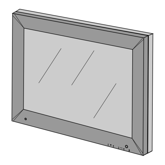
Page 6: Dimensions
DIMENSIONS 197.78 306.02 MML1801... - Page 7 DIMENSIONS MML1801...
-
Page 8: Installation
If you ordered the monitor with the resistive touchscreen option, the following items should also be included: ● User’s manual of touchscreen ● Touchscreen cable PEDESTAL (standard) With the built-in pedestal you can tilt the monitor for a most comfortable viewing angle shown in fi gure 8a. MML1801 5° 15° fi g. 8a... -
Page 9: Mounting Instruction
The pedestal must be fi xed at monitor with N° 6 screws M3x10 (included into the BOX) as shown in fi gure 9a. ARM VESA PLATE fi g. 9b An arm with VESA (100x100) interface must be fi xed at monitor with N° 4 screws M4x10 as shown in fi gure 9b. MML1801... -
Page 10: Connecting Instruction
fi g 10b Insert the plug end of the power cord into a grounded wall outlet. For added protection, use a surge protector between the AC adapter and the electrical wall outlet to prevent sudden current variations from reaching the monitor MML1801... -
Page 11: Connecting Analog Video
Turn the monitor on fi rst, and then turn on the computer. CONNECTING COMPOSITE VIDEO (BNC) With the power the computer and the monitor turned off, connect the supplied video cable from the monitor to the computer’s video port (see fi g. 11b) fi g. 11b MML1801... -
Page 12: Connecting Digital Video
RS-232 serial port using the proper cable (see fi g. 12b) fi g. 12b NOTE: Follow the instructions included on the enclosed CD for installing the Touchscreen drivers on your system. Following driver software installation, calibrate your Touchscreen to the system following the procedure described on the enclosed CD. MML1801... -
Page 13: Input Instruction
Pin 18 : D0_RX + (T.M.D.S.) Pin 19 : GND (Data 0 shield) Pin 20 : N.C. Pin 21 : N.C. Pin 22 : GND (Clock shield) Pin 23 : CK_RX + (T.M.D.S.) Pin 24 : CK_RX - (T.M.D.S.) MML1801... -
Page 14: Control Panel Description
- MENU SELECT - / BRIGHTNESS Recall to 500 Cd/m² - MENU SELECT + - ENTER (Store/Source-Select) Light sensor GREEN= 500 cd/m² / Power-on < 500 cd/m² ORANGE= Stand-by Brightness Adjust - Brightness Adjust + Menu select - MML1801 menu Enter Menu select + fi g. 14a Power Switch... -
Page 15: (Osd) On Screen Display
│ └───── EXIT ├──────────ABC OFF ├──────────ABC REDUCED └──────────ABC FULL ├──────────TG3-PMS ├──────────LINEAR ├──────────DICOM └──────────MONITOR TG3 ┐ ├──────────VIDEO OFFSET ├──────────VIDEO GAIN ├──────────STORE VIDEO └──────────EXIT ├──────────AUTO-SETUP ON MODESET │ ├──────────ENABLED │ ├──────────DISABLED │ └──────────ONLY ONCE ├──────────AUTO-CLOCK FEATURE │ ├──────────ENABLED │ └──────────DISABLED └──────────EXIT MML1801... -
Page 16: Osd Key Functions
Languages OSD Settings Video Source Keyboard Option Exit MML1801 OSD KEY FUNCTIONS Description It activates the OSD MAIN MENU if this is not active, otherwise selects and executes a desired OSD Special Function. When main menu or sub-menu is active, it allows to move or scroll to the previous (upper) item or decrement the magnitude of the parameter. -
Page 17: Information
Operating Hours Video timing number 3) To press Enter buttton to return to Main Menu. FIMI-Philips MML1801 Ver CO.62-DO.62 6.3.0 Image Adjust 1) Press Enter button when the Image Adjust is highlighted on Main Menu. The Image Adjust window appears. -
Page 18: Horizontal Position
1) Press Enter button when the Image Enhancement is highlighted on Image Adjust. The Image Enhancement window appears. 2) Press the Menu + or Menu - button until the desired item is highlighted. MML1801 Image Adjust Horizontal Position Vertical position... -
Page 19: Transfer Function
3) Press the Enter button to confi rm your selection and return to Image Enhancement window 6.3.7 Advanced 1) Press Enter button when the Adavanced is highlighted on Main Menu The Advanced window appears. ABC Selection ABC Off ABC Reduced ABC Full Transfer Function TG3 - PMS Linear DICOM Monitor TG3 MML1801... -
Page 20: Phase Adjust
Note: It is necessary to use video pattern dedicated to obtain the best result 3) When the position is adjusted, press the Enter buton to return to Advanced window 4) To select Exit and press again Enter button to return to Image Adjust or select Service. MML1801 Advanced Phase Adjust... -
Page 21: Service
2) Press Adjust + or Adjust - button until the desired item is highlighted 3) Press the Enter button to confi rm your selection and return to Auto-Setup Options window Service Video Offset Video Gain Store Video Exit Auto-Setup Options Auto-Setup On Modeset Auto-Clock Feature Exit MML1801... -
Page 22: Auto-Clock Feature
1) Press Enter button when the Auto-Level is highlighted on Advanced. To perform an automatic calibration of the video signal. Valid only BNC, DSUB-SOG and DSUB video source. 2) Select Exit and press again Enter button to return to Image Adjust. MML1801 Auto-Setup On Modest Enabled Disabled... -
Page 23: Restore Factory Preset
2) Press the Menu + or Menu - button until the desired item is highlighted. Languages English Français Deustch Español Italiano OSD Settings OSD Position OSD Size OSD Transparency OSD Timeout Exit OSD Position Horizontal Position Vertical position Exit MML1801... -
Page 24: Osd Position
2) Press the Adjust + or Adjust - button until the desired item is highlighted. Normal Standard dimensions Double Double dimension 3) Press the Enter button to confi rm your selection and return to OSD Settings window MML1801 OSD Position Horizontal Position Vertical position... -
Page 25: Osd Size
OSD Size OSD Transparency OSD Timeout Exit OSD Timeout 10 Sec. 20 Sec. 30 Sec. 45 Sec. 60 Sec. 90 Sec. 120 Sec. Disabled Video Source DSUB (Ht. and Vt. Sync.) DSUB-SOG (Green Input) DSUB (Ht. + Vt. Sync.) Exit MML1801... -
Page 26: Keyboard Option
○ Brightness + ○ Menu - The dialog (Fig. 26a) will disappear any time a wrong key will be pressed. For every right key pressed a “plus” characters appears in dialog of Fig. 26a. MML1801 Check Input Signal (XXX) Keyboard Option... - Page 27 INTENTIONALLY LEFT BLANK...
- Page 28 3119 206 1404.1...