Toshiba VF-PS1 Instruction Manual
Totally enclosed box type inverter
Hide thumbs
Also See for VF-PS1:
- Instruction manual (317 pages) ,
- Function manual (27 pages) ,
- Instruction manual (27 pages)
Table of Contents
Advertisement
Quick Links
Instruction Manual
Totally enclosed box type Inverter
TOSVERT
1. Make sure that this instruction manual is delivered to the end user of the
inverter unit.
2.This manual gives supplementary information of some items referred in the
instruction manual E6581386 supplied with the product. Read this manual
and E6581386 before installing or operating the inverter unit, and store them
in a safe place for reference.
PS1
TM
VF-
NOTICE
E6581429
I
Safety
precautions
II
Introduction
Contents
1
Read first
2
Connection
of equipment
3
Operations
Searching and
4
setting
parameters
5
Monitoring the
operation status
6
List of function
key functions
Measures to
7
satisfy the
standards
Selection of
8
peripheral
devices
9
Table of
parameters
10
Specifications
Advertisement
Table of Contents

Related Manuals for Toshiba VF-PS1


Summary of Contents for Toshiba VF-PS1
-
Page 1: Instruction Manual
E6581429 Safety precautions Introduction Contents Read first Instruction Manual Connection of equipment Totally enclosed box type Inverter Operations Searching and setting TOSVERT parameters Monitoring the operation status List of function key functions Measures to satisfy the standards Selection of peripheral devices Table of parameters... -
Page 3: Instruction Manual
E6581429 I. Safety precautions Thoroughly familiarize yourself with the symbols and indications shown in “I. Safety Precautions,” of the instruction manual E6581386 and below, and then continue to read manuals. Make sure that you observe all cautions given. Transportation & installation Caution •... - Page 4 E6581429 II. Introduction Thank you for your purchase of the totally enclosed box type for IP54 Inverter, “TOSVERT VF-PS1”. Note) Drives with UL Type 12 conformity are optional. Contact your nearest Toshiba inverter distributor for them.
-
Page 5: Table Of Contents
E6581429 - Contents - I. Safety precautions ······················································································································································ II. Introduction ································································································································································ Read first····························································································································································· Check the product ········································································································································ Contents of the product code ······················································································································· Structure of the main body ··························································································································· 1.3.1 Names and functions ···························································································································· 1.3.2 Detaching the cover ······························································································································ A-11 1.3.3 Grounding capacitor switching method ·································································································... -
Page 7: Read First
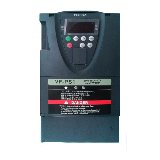
Additional functions II specification code L: Built-in EMC filter 004:0.4kW 185:18.5kW TOSVERT 4: 380V~480V P: Provided E: Totally enclosed (class A) : Special VF-PS1 series 007:0.75kW 220:22kW box type specification code 015:1.5kW 300:30kW Y: Others basic filter 022:2.2kW 370:37kW is a number) -
Page 8: Structure Of The Main Body
E6581429 1.3 Structure of the main body 1.3.1 Names and functions 1) Outside view Operation panel (Note) [ Front view ] [ Side view ] Wiring port plate Cooling fan [ Bottom view ] Note: Operation panel is not attached to the inverter main unit at the delivery. Attach the panel at the position of the upper figure before installing the inverter. -
Page 9: List Of Function
E6581429 Operation panel Totally enclosed box type VF-PS1 series have a special operation panel. (2) (3) (4) (5) (10) (1): LCD panel For explanation of windows displayed, see the next page. (2) to (5): [F1] to [F4] function keys The function of each function key varies depending on the window currently displayed. - Page 10 E6581429 LCD panel This section explains the features of windows available, using the top window of Status Monitor Mode as an example. Status Monitor Mode Real-time information Rotative direction Frequency reference 60.0Hz Output current Input voltage Output voltage (1): Displays the mode currently selected. (2): Displays the operating status of the inverter with a graphical symbol.
- Page 11 E6581429 2) Main circuit terminal VFPS1-4007PLE~4022PLE PO PA/+ PB PC/- M4 screw U/T1 V/T2 W/T3 R/L1 S/L2 T/L3 Grounding capacitor switching switch Grounding terminal (M5 screw) VFPS1-4007PDE~4022PDE PO PA/+ PB PC/- M4 screw M4 slotted head screw R/L1 S/L2 T/L3 U/T1 V/T2 W/T3 Grounding terminal (M5 screw)
- Page 12 E6581429 VFPS1-4037PDE, 4055PDE PO PA/+ PC/- M4 slotted head screw M4 screw R/L1 S/L2 T/L3 U/T1 V/T2 W/T3 Grounding terminal (M5 screw) VFPS1-4075PLE, 4110PLE M5 screw R/L1 S/L2 T/L3 PO PA/+ PB PC/- U/T1 V/T2 W/T3 Grounding capacitor switching switch Grounding terminal(M5 screw) VFPS1-4075PDE, 4110PDE M4 slotted head screw...
- Page 13 E6581429 VFPS1-4150PLE Grounding capacitor M5 screw switching switch R/L1 S/L2 T/L3 PA/+ PC/- U/T1 V/T2 W/T3 Grounding terminal(M5 screw) VFPS1-4150PDE M4 slotted head screw M5 screw PA/+ PC/- U/T1 V/T2 W/T3 R/L1 T/L3 S/L2 Grounding terminal (M6 screw) Grounding terminal (M5 screw) VFPS1-4185PLE, 4220PLE Grounding capacitor...
- Page 14 E6581429 VFPS1-4185PDE, 4220PDE M5 slotted head screw M6 screw PA/+ PC/- U/T1 V/T2 W/T3 R/L1 T/L3 S/L2 Grounding terminal(M6 screw) Grounding terminal(M5 screw) VFPS1-4300PLE Grounding capacitor switching switch M10 hexagon socket set screw PA/+ Grounding terminal (M10 hexagon socket set screw) Grounding terminal(M5 screw) VFPS1-4300PDE M5 slotted head screw...
- Page 15 E6581429 VFPS1-4370PLE, 4450PLE Grounding capacitor switching switch M10 hexagon socket set screw PA/+ Grounding terminal (M10 hexagon socket set screw) Grounding terminal(M5 screw) VFPS1-4370PDE, 4450PDE M6 slotted head screw M10 hexagon socket set screw R/L1 S/L2 T/L3 PA/+ Grounding terminal (M10 hexagon socket set screw) Grounding terminal(M6 screw) Grounding terminal(M5 screw) VFPS1-4550PLE~4900PLE...
- Page 16 E6581429 VFPS1-4550PDE~4900PDE M20 hexagon socket head cap screw M16 hexagon socket set screw U/T1 V/T2 W/T3 R/L1 S/L2 T/L3 PA/+ PC/- grounding terminal(M16 hexagon socket set screw) grounding terminal(M8 screw) Following power terminals are cage type ones. - Input terminals of VFPS1-4007PDE to 4220PDE - All power terminals of VFPS1-4300PLE to 4900PLE, VFPS1-4300PDE to 4900PDE For tightening torque and cable stripping length, refer to the table below.
-
Page 17: Detaching The Cover
E6581429 1.3.2 Detaching the cover Danger • Never remove the front cover while power is on or within 15 minutes after power off. Never turn on the power while the front cover is open. Circuit boards are exposed when the front cover is removed and contact with them will result in Mandatory electric shock. -
Page 18: Grounding Capacitor Switching Method
E6581429 Charge lamp Charge lamp is inside the unit front cover open. Never remove the front cover while power is on or within 15 minutes after power off, nor turn on the power while the front cover is open. They can result in electric shock. Location of charge lamp depends on type form. -
Page 19: In Case Of Adopting External Braking Resistor (Optional
E6581429 VFPS1-4300PLE~4900PLE A switch or switches enable to reduce grounding capacitance. To change the capacitance Large Small from small to large, push in the button. (Factory default position) To change the capacitance Large Small from large to small, pull up the button. -
Page 20: Notes On The Application
10cm or more –10°C to 50°C. Where ambient temperature will rise above 40°C, derating of rated current is needed. VF-PS1 5cm or more • Install the inverter in a well-ventilated place and mount it 5cm or more on a flat metal plate in portrait operation. -
Page 21: Connection Of Equipment
E6581429 2. Connection of equipment 2.1 Cautions on wiring Wiring • Following power terminals are cage type ones. - Input terminals of VFPS1-4007PDE to 4220PDE - All power terminals of VFPS1-4300PLE to 4900PLE, VFPS1-4300PDE to 4900PDE For tightening torque and cable stripping length, refer to 1.3.1 2). •... -
Page 22: Standard Connections
E6581429 2.2 Standard connections [Standard connection diagram – sink logic] The figure below shows an example of typical wiring in the main circuit 200V 0.4-45kW/400V 0.75-75kW inverter. This inverter has following three setting/monitor modes. *1: A DC reactor (DCL) is incorporated in the position shown the figure above. External DC reactor cannot be used. *2: For 30kW to 90kW drives, an additional DC reactor is incorporated in the position shown the figure above. - Page 23 E6581429 [Standard connection diagram – source logic] The figure below shows an example of typical wiring in the main circuit 200V 0.4-45kW/400V 0.75-75kW inverter. This inverter has following three setting/monitor modes. *1: A DC reactor (DCL) is incorporated in the position shown the figure above. External DC reactor cannot be used. *2: For 30kW to 90kW drives, an additional DC reactor is incorporated in the position shown the figure above.
-
Page 24: Description Of Terminals
Description of terminals 2.3.1 Main circuit terminals This diagram shows an example of wiring of the main circuit. Use options if necessary. Power supply and motor connections VF-PS1 Connect the power Connect the motor Power supply cables to RL1, S/L2, cables to U/T1, V/T2 and T/L3. -
Page 25: Operations
E6581429 3. Operations 3.1 Settings to be made at first power on When the inverter is powered on at the first time after purchase, the Language selection window shown below appears on the LCD panel. In this window, select the language you want to display on the screen. 1. -
Page 26: Setting/Monitor Modes
E6581429 3.2 Setting/monitor modes This inverter has following three setting/monitor modes. (1) Top View Mode When the inverter is powered on, it enters this mode first. The top window displays the operating status. In this mode, you can set a panel operation frequency, use a function key as the EASY key, and so on. ⇒... -
Page 27: Operation In Top View Mode
E6581429 3.3 Operation in Top View Mode When the inverter is powered on, it enters this mode first, which allows you to monitor the operating status, set an operation frequency, use EASY key, and switch between languages. When Panel Jog Run is selected, a jog run frequency also can be specified in this mode. Explanation of the top window Display of commands Display of... -
Page 28: Using An Easy Key Function
E6581429 2. After selecting the position of a figure you want to change, specify/confirm a value with the control dial. (In this example, 30.0Hz is specified.) Basic Parameters Functions of function keys Panel frequency The functions keys allow you to select the position or decimal place Output frequency of each figure (operation frequency) you want to increment or 30.0Hz... -
Page 29: Selecting A Language To Be Displayed
E6581429 (2) Local / Remote key function • “Loc/ ” is displayed. ([F1] key is in OFF State) In this state, remote controlled operation via terminal board is available. • If the [F1] key is pressed while “Loc/ ” is displayed, it turns to “ /Rem”. -
Page 30: Emergency Stop / Reset Operation
E6581429 1. Press the [F4] key to carry out jog run. The jog run frequency is displayed on the screen. Top View Mode (In this example, the operation frequency is set at 5.0Hz.) FWD 60.0 Hz Operation continues as long as the [F4] key is pressed, and it stops when the [F4] key is released. -
Page 31: Searching And Setting Parameters
E6581429 4. Searching and setting parameters In the Parameter Setup Mode, you can set basic parameters and extended parameters. This mode also allows you to use the history function (parameter “auh” in the manual E6581386) and the changed parameter search function (parameter “gru” in the manual E6581386) easily by simply selecting the desired function from a menu. -
Page 32: Setting A Basic Parameter
E6581429 4.2 Setting a basic parameter When Quick mode is selected using the EASY key function, skip step 1. Go straight to step 2. 1. Select/confirm “Basic parameters” using the control dial. The Basic Parameters window appears. Parameter Setup Mode Functions of function keys Basic Parameters :Automatic acc/dec... -
Page 33: Setting An Extended Parameter
E6581429 3. Using the control dial, select/confirm an item or specify/confirm a value. (In this example, “Panel / LCD-option” is selected and confirmed or frequency of 90.0Hz is specified and confirmed.) When the change you made is saved, the title of the •... -
Page 34: Searching For Parameters Whose Setting Has Been Changed (Changed Parameters
E6581429 4.4 Searching for parameters whose setting has been changed (Changed Parameters) This function displays parameters whose current settings are different from their default settings, and their present settings. 1. Select/confirm “Changed Parameters” using the control dial. The Changed Parameters window appears. Parameter Setup Mode Changed Parameters Functions of function keys... -
Page 35: Monitoring The Operation Status
E6581429 5. Monitoring the operation status In the Status Monitor Mode, you can monitor various kinds of statuses and information, such as the operating status of the inverter, information on the terminal board, and trip information. Status Monitor Mode Real-time information Functions of function keys Rotative direction Frequency reference... -
Page 36: Displaying Details Of An Item Monitored
E6581429 5.1 Displaying details of an item monitored 1. Select/confirm the desired item using the control dial. (Ex. Select/confirm “Output current”) The monitor window of the item selected appears. Status Monitor Mode * Depending on the item selected, no monitor window may be Output current displayed. -
Page 37: List Of Function Key Functions
E6581429 6. List of function key functions Each function key is corresponding to the function whose abbreviation or graphic symbol is displayed at the bottom of the window and over the key. And by pressing a function key, corresponding function is performed. Top View Mode FWD 60.0 Hz STOP... -
Page 39: Measures To Satisfy The Standards
E6581429 7. Measures to satisfy the standards 7.1 How to cope with the CE standards 7.1.1 Measures to satisfy the EMC directive Concrete measures to EMC directive are shown below. (1) This inverter installs a EMC filter inside. So the conducted and radiated noise can be reduced. EMC directive compliance Requirements PWM carrier... - Page 40 E6581429 Ex. Countermeasure – inverter wiring PLE - type PDE - type Power supply wiring (Shielded cables) Power supply wiring (Shielded cables) R/L1, S/L2, T/L3 Motor wiring (Shielded cables) R/L1, S/L2, T/L3 Motor wiring (Shielded cables) (Fix with nonmetal cable gland) U/T1, V/T2, W/T3 (Fix with nonmetal cable gland) U/T1, V/T2, W/T3...
- Page 41 (47.5) (37.4) (18.8) 63.5 50.5 16.5 4550PDE~4900PDE 170.5 191.5 (60.5) (47.5) (18.8) Note) Values in ( ) are for UL Type 12 conformity type. Drives with UL Type 12 conformity are optional. Contact your nearest Toshiba inverter distributor for them.
-
Page 42: Conforming To Ul Type
*2: The value of the UL rated output current is applicable when the carrier frequency (CF) is less than the value shown in the table. *3: The cables used must be 75°C copper cables within 40°C ambient temperature. 7.2.2 Conforming to UL Type 12 Drives with UL Type 12 conformity are optional. Contact your nearest Toshiba inverter distributor for them. -
Page 43: Selection Of Peripheral Devices
E6581429 8. Selection of peripheral devices 8.1 Selection of wiring materials and devices Wire size Applicable Main circuit Braking resistor / DC terminal motor Inverter type form Braking unit Earth cable Input terminal Output terminal (optional) (kW) (Optional) (R,S,T) (U,V,W) 0.75 VFPS1-4007PLE/PDE VFPS1-4015PLE/PDE... -
Page 44: Selection Of Wiring Equipment
VFPS1-4900PLE/PDE 171.8 (*1): Selections for use of the Toshiba 4-pole standard motor with power supply voltage of 400V-50Hz. (*2): Choose the MCCB according to the power supply capacity. For comply with UL and CSA standard, use the fuse certified by UL and CSA. -
Page 45: Table Of Parameters
E6581429 9. Table of parameters For parameters, refer to the instruction manual E6581386. However, for totally enclosed box type drives, only following points are different. Title Communication No. Function Adjustment range 0300 PWM carrier frequency 1.0~16.0kHz *1 *1: Although instruction manual E6581386 describes that the carrier frequency is adjustable between 2.5 to 8.0kHz for 90kW model, it is adjustable between 1.0 to 16.0kHz for totally enclosed box type 90kW model. -
Page 47: Specifications
Note 3: An external power supply backup available (optional) (Type: CPS002Z) Note 4: ±10% when the inverter is used continuously (load of 100%). Note 5: Drives with UL Type 12 conformity are optional. Contact your nearest Toshiba inverter distributor for them. -
Page 48: Operations··························································································································································· C
E6581429 2) Common specification Item Specification Control system Sinusoidal PWM control Output voltage adjustment Main circuit voltage feedback control. (Switchable between automatic adjustment/fix/control off) Setting between 0.01 to 500Hz. Default max. frequency is set to 0.01 to 60Hz. Output frequency range Maximum frequency adjustment (30 to 500Hz) Minimum setting steps of 0.01Hz: operation panel input (60Hz base),... - Page 49 E6581429 (Continued) Item Specification Stall prevention during operation, overload limit, overload, undervoltage on power source side, DC circuit Alarms undervoltage, setting error, in retry, upper limit, lower limit. Overcurrent, overvoltage, fin overheat, short circuit on the load side, ground fault on the load side, inverter overload, arm overcurrent at starting, overcurrent on the load side at starting, EEPROM error, Causes of RAM error, ROM error, transmission error, (dynamic braking resistor overcurrent/overload), (emergency...
-
Page 50: Outside Dimensions And Weights
E6581429 10.2 Outside dimensions and mass Outside dimensions and weight Applicable Applicable Approximate Dimensions (mm) Inverter type Drawing motor motor mass (kW) (HP) (kg) [Note 1] 0.75 VFPS1-4007PLE(PDE) 13(15) VFPS1-4015PLE(PDE) VFPS1-4022PLE(PDE) VFPS1-4037PLE(PDE) 16(18) VFPS1-4055PLE(PDE) VFPS1-4075PLE(PDE) 20(23) VFPS1-4110PLE(PDE) VFPS1-4150PLE(PDE) 25(29) 18.5 VFPS1-4185PLE(PDE) 36(41) VFPS1-4220PLE(PDE) - Page 51 E6581429 Fig. C Fig. D Fig. E Fig. F...
- Page 52 E6581429 Fig. G Fig. H...