ABB CM30 User Manual
Universal process controllers, 1/4 and 1/2 din
Hide thumbs
Also See for CM30:
- User manual (114 pages) ,
- Manual (88 pages) ,
- Communications supplement (30 pages)
Table of Contents
Advertisement
Quick Links
User Guide – Extended / Dual Functionality IM/CM/ED–EN Rev. B
ControlMaster CM30 and CM50
Universal process controllers,
1
/
and
1
/
DIN
4
2
The Company
We are an established world force in the design and manufacture of instrumentation for industrial process
control, flow measurement, gas and liquid analysis and environmental applications.
As a part of ABB, a world leader in process automation technology, we offer customers application expertise,
service and support worldwide.
We are committed to teamwork, high quality manufacturing, advanced technology and unrivalled service and
support.
The quality, accuracy and performance of the Company's products result from over 100 years experience,
combined with a continuous program of innovative design and development to incorporate the latest
technology.
Advertisement
Table of Contents

Related Manuals for ABB CM30


Summary of Contents for ABB CM30
- Page 1 Universal process controllers, As a part of ABB, a world leader in process automation technology, we offer customers application expertise, service and support worldwide. We are committed to teamwork, high quality manufacturing, advanced technology and unrivalled service and support.
- Page 2 Serial No. Reset Hour Linearizer 1 (2) Hardware Revision Software Revision *When in Advanced Level (configuration mode), press and hold the key to return to the standard Operator page – see Fig. 3.1, page 5. **Enabled for CM30 and CM50 only...
-
Page 3: Table Of Contents
4.4.1 Removing the Controller from its Case ......................... 9 4.4.2 Resetting Jumper Links ....................10 Electrical Connections ......................11 4.5.1 CM30 Electrical Connections ..................12 4.5.2 CM50 Electrical Connections ..................13 4.5.3 Analog Inputs ......................14 4.5.4 Frequency / Pulse Input ....................15 4.5.5 Digital Input / Output .................... - Page 4 ControlMaster CM30 and CM50 Universal process controllers, Contents Templates and Functionality ......................64 Basic Templates ........................64 8.1.1 Single Loop / Single Loop with Remote Setpoint ............64 Standard Templates ......................65 8.2.1 Auto / Manual Station (Low Signal Selection / Digital Signal Selection) ......65 8.2.2 Analog Backup Station (Low Signal Selection / Digital Signal Selection) .......
-
Page 5: Safety
ControlMaster CM30 and CM50 Universal process controllers, 1 Safety 1 Safety Information in this manual is intended only to assist our customers in the efficient operation of our equipment. Use of this manual for any other purpose is specifically prohibited and its contents are not to be reproduced in full or part without prior approval of the Technical Publications Department. -
Page 6: Introduction
ControlMaster CM30 and CM50 Universal process controllers, 2 Introduction 2 Introduction This manual provides details for the ControlMaster CM30 ( DIN) and CM50 ( DIN) controllers with Extended / Dual Loop functionality Note. Read all relevant sections of this guide before configuring the system or modifying system parameters. -
Page 7: Display Overview
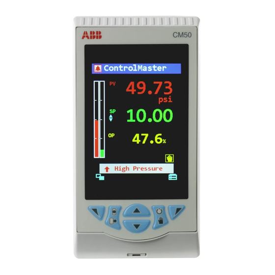
Indicates which Manual Local value is adjusted Mode Setpoint by the keys Auto Totalizer Process Mode Running Alarm Icons Totalizer Autotune Stopped Adaptive Feedforward Gain Fig. 3.1 ControlMaster CM30 and CM50 Displays and Icons IM/CM/ED–EN Rev. B... -
Page 8: Front Panel Keys
ControlMaster CM30 and CM50 Universal process controllers, 3 Display Overview 3.1 Front Panel Keys Fig. 3.2 Front Panel Keys Navigation (left) / Operator Level access key – see page 16. Local / Remote setpoint mode selection key. Up / Down keys – navigate up / down menus and increase / decrease displayed values. -
Page 9: Installation
ControlMaster CM30 and CM50 Universal process controllers, 4 Installation 4 Installation Caution. Select a location away from strong electrical and magnetic fields. If these cannot be avoided, particularly in applications where 'walkie talkies' are used, connect using screened cables within grounded metal conduit 4.1 Siting... -
Page 10: Dimensions
–0 +0.8 Controllers can be –0 close-stacked to (3.6) +0.03 DIN 43835 –0 30 (1.18) 14 (0.55) Fig. 4.3 ControlMaster CM30 Dimensions Dimensions in mm (in.) 23 (0.9) 123 (4.9) 76 (3.0) 137.8 (5.6) (5.4) 146 (5.7) +0.7 –0 (2.7) (+0.03... -
Page 11: Mounting
ControlMaster CM30 and CM50 Universal process controllers, 4 Installation 4.3 Mounting 4.4 Jumper Links for Relay Outputs ControlMaster is designed for panel mounting. For The factory-set default for relay action is N/O. NEMA4X protection, a panel thickness of 2.5 mm 4.4.1 Removing the Controller ... -
Page 12: Resetting Jumper Links
Fig. 4.7. 2. If necessary, move the link to select the relay action required (N/O or N/C). CM30 Option Board 1 / 1a LK1 = Relay O/P 2 LK2 = Relay O/P 3 LK3 = Relay O/P 4... -
Page 13: Electrical Connections
ControlMaster CM30 and CM50 Universal process controllers, 4 Installation 4.5 Electrical Connections Warning. The controller is not fitted with a switch therefore a disconnecting device such as a switch or circuit breaker conforming to local safety standards must be fitted to the final installation. -
Page 14: Cm30 Electrical Connections
**N/O (factory default) or N/C contact selection made via internal jumper links – see page 9 ***200 mA Type T fuse (mains AC) or 2 A Type T fuse (24 V DC) and external isolating switch Fig. 4.8 CM30 Electrical Connections IM/CM/ED–EN Rev. B... -
Page 15: Cm50 Electrical Connections
ControlMaster CM30 and CM50 Universal process controllers, 4 Installation 4.5.2 CM50 Electrical Connections Rear View Rear View Standard Connections Option Board 1 Analog Input 3 Analog Input 1 Analog Input 2 Analog Input 4 TX PSU Tx PSU Digital Output + External... -
Page 16: Analog Inputs
For mA input types, to ensure loop continuity when the controller is switched off, fit a suitably rated diode (for example, type 1N4148 or equivalent) as shown. Note .3 Leads must have equal resistance, not exceeding 20 each. Fig. 4.11 ControlMaster CM30 and CM50 Optional Analog Inputs (3 and 4) IM/CM/ED–EN Rev. B... -
Page 17: Frequency / Pulse Input
CM30: Terminal 43 or 35 + External CM50: Terminal 7 or 30 Load CM30: Terminal 44 or 45; 36, 37, 38 or 39 CM50: Terminal 8 or 9; 31, 32, 33 or 34 Digital Input/Output – CM30: Terminal 46 or 40... -
Page 18: Operator Level Menus
Other active Out of Spec High Latch Alarm diagnostic / alarm states can be viewed on the Check Function Low Latch Alarm Diagnostic View – see page 17. Fig. 5.1 ControlMaster Diagnostic Status Bar (ControlMaster CM30 Shown) IM/CM/ED–EN Rev. B... -
Page 19: Diagnostic View
ControlMaster CM30 and CM50 Universal process controllers, 5 Operator Level Menus 5.2 Diagnostic View 5.4 Access Level The Diagnostic View can be selected from the Level Access Operator / View Select menu. All currently active Logout Displayed after Basic or Advanced level diagnostic alarm states are displayed in the are accessed. -
Page 20: Basic Level
ControlMaster CM30 and CM50 Universal process controllers, 6 Basic Level 6 Basic Level The Basic menu provides access to the tunable control settings and setpoint Menu values. Basic Select Exit Loop 1 (2) Setpoints Local Setpoint 1 (4) The local setpoint value required. If this value is adjusted in the Operator Level (see page 16) its value in here is also updated. - Page 21 ControlMaster CM30 and CM50 Universal process controllers, 6 Basic Level …Basic Loop 1 (2) Control On/Off Hysteresis Sets the hysteresis value in engineering units. Note. Applicable only if Control Type is On/Off – see page 39. Setpoint Hysteresis Hysteresis Value...
- Page 22 ControlMaster CM30 and CM50 Universal process controllers, 6 Basic Level …Basic / …Loop 1 (2) Control / … Autotune First Step Defines the maximum size of the first output step in the autotuning process. Autotune adjusts the output step magnitude according to the process noise and response to provide a reliable measurement of the process characteristics with the minimum disturbance of the process.
- Page 23 ControlMaster CM30 and CM50 Universal process controllers, 6 Basic Level …Basic Loop 1 (2) Mot Valve Motorized Valve Output With Feedback Open Relay Motorized (OP x Ratio) + Bias Valve Controller Close Relay Position Feedback Motorized Valve Output Without Feedback (Boundless)
- Page 24 ControlMaster CM30 and CM50 Universal process controllers, 6 Basic Level …Basic / …Loop 1 (2) Mot Valve Calculation for Control Pulses (Boundless Control) The following calculations are for guidance when setting deadband, proportional and integral values: Minimum 'On' time of integral action pulses (for a fixed control deviation):...
- Page 25 ControlMaster CM30 and CM50 Universal process controllers, 6 Basic Level …Basic Loop 1 (2) Time Prop The active time of the output pulse is proportional to the value of the control output. With 100 % output the pulse is active for the complete cycle time, for example:...
-
Page 26: Advanced Level
ControlMaster CM30 and CM50 Universal process controllers, 7 Advanced Level 7 Advanced Level 7.1 Device Setup Provides access to standard setup parameters to determine the type of Menu Device Setup control / indication required. Also provides the ability to create non-standard configurations for special application requirements. - Page 27 ControlMaster CM30 and CM50 Universal process controllers, 7 Advanced Level …Device Setup / …Basic Setup Config Action The Config Action parameter is used to determine how the controller and controller outputs behave when the Advanced level is entered – see page 24.
-
Page 28: Display
ControlMaster CM30 and CM50 Universal process controllers, 7 Advanced Level 7.2 Display Used to setup the operator page, displayed language and display hardware Menu Display settings. Exit Select Language Selects the language on the controller's local display. Operator Templates Enables up to 4 operator pages to be configured to suit the application requirements. - Page 29 ControlMaster CM30 and CM50 Universal process controllers, 7 Advanced Level …Display Operator Functions Autoscroll When enabled (On), Operator pages (see page 16) are scrolled continuously at intervals of 10 seconds per page. Soft Key Function Assigns a dedicated function to the Navigation key (right) – see page 6.
- Page 30 Contrast Increases / Decreases the display contrast to suit local environmental conditions (enabled for CM30 and CM50 only). *When the controller is setup for the first time, the Scale Low and Scale High values default to match the engineering range.
- Page 31 ControlMaster CM30 and CM50 Universal process controllers, 7 Advanced Level …Display Date & Time Sets the date format, local time / date and daylight saving start / end times. Date Format Selected from: DD–MM–YYYY, MM–DD–YYYY, YYYY–MM–DD. Time & Date Sets the controller’s time and date.
- Page 32 ControlMaster CM30 and CM50 Universal process controllers, 7 Advanced Level …Display Customise Pages The contents and appearance of each Operator Page (see page 16) can be customized to meet particular user requirements. Page Number Selects the Operator Page (1 to 4) to be customized.
- Page 33 ControlMaster CM30 and CM50 Universal process controllers, 7 Advanced Level …Display / …Customise Pages / …Parameters A user-programmable, 3-character alphanumeric tag used to identify each parameter. State 0 Tag A user-programmable, 8-character alphanumeric tag displayed when the state of the selected parameter has a value of 0.
-
Page 34: Input/Output
ControlMaster CM30 and CM50 Universal process controllers, 7 Advanced Level 7.3 Input/Output Enables analog and digital inputs / outputs and relays to be configured. Menu Input/Output Exit Select Analog Inputs Analog Input 1 (4)* Input Type Millivolts, Milliamps, Volts, Resistance (Ohms), RTD, Thermocouple, Digital volt-free, 24V Digital, Freq. - Page 35 ControlMaster CM30 and CM50 Universal process controllers, 7 Advanced Level …Input/Output / …Analog Inputs / …Analog Input 1 (4) Eng. Low Specifies the engineering low (minimum) value. For example, for an electrical input range of 4.0 to 20.0 mA, representing a pressure range of 50 to 250 bar, set the Eng Low value to 50.0 and the Eng High value to 250.0.
- Page 36 Analog Output 1 (2) Note. Analog Output 2 is available only if an option board is fitted – see pages 12 (CM30) and 13 (CM50) for option board details. Output Type Selects the output type required (applicable only to Analog Output 1).
- Page 37 ControlMaster CM30 and CM50 Universal process controllers, 7 Advanced Level …Input/Output Digital I/O Digital IO 1 (6) Type Sets the Digital IO to operate as an output or an input. No action taken. Output The Digital IO operates as an output.
-
Page 38: Control
ControlMaster CM30 and CM50 Universal process controllers, 7 Advanced Level 7.4 Control Enables the setpoints, control functions and outputs to be configured. Menu Control Exit Select Loop 1 (2) Setpoints The controller can have up to 4 independent local setpoint values, remote setpoint functionality and the ability to limit the absolute values and rate of change of the control setpoint. - Page 39 ControlMaster CM30 and CM50 Universal process controllers, 7 Advanced Level …Control / …Loop 1 (2) Setpoints RSP Ratio When the remote (external) setpoint is selected the control setpoint value is: (ratio x remote setpoint input) + bias RSP Bias Sets the remote setpoint bias in engineering units – see Appendix C, page 83 for description of analog input units.
- Page 40 ControlMaster CM30 and CM50 Universal process controllers, 7 Advanced Level …Control / …Loop 1 (2) Setpoints / …Select Sources Remote Select The source required to select remote setpoint mode Remote (or remote ratio) mode. Setpoint Mode Loc/Rem Toggle The source required to select either local or remote Remote setpoint mode.
- Page 41 ControlMaster CM30 and CM50 Universal process controllers, 7 Advanced Level …Control / …Loop 1 (2) Control Control Type Selects the basic type of controller required. Standard proportional, integral and derivative control. pPI controller: pPI Controller Process Deadtime Model Model Without...
- Page 42 ControlMaster CM30 and CM50 Universal process controllers, 7 Advanced Level …Control / …Loop 1 (2) Control Control Action If the required controller action is known it can be set using this parameter. Otherwise it can be set to Unknown and Autotune (see page 19) determines and selects the correct action.
- Page 43 ControlMaster CM30 and CM50 Universal process controllers, 7 Advanced Level …Control / …Loop 1 (2) Control / …Gain Scheduling Mode Turns the gain scheduling function On or Off. Source The Gain Scheduling (GSRef) reference signal – see Appendix A, page 79 for description of sources.
- Page 44 ControlMaster CM30 and CM50 Universal process controllers, 7 Advanced Level …Control / …Loop 1 (2) Control / …FeedForward Mode Feedforward control is disabled. Static Gain Gain applied by FeedForward block is a fixed value set by the user. Adaptive Gain Gain applied by the FeedForward block is set by the controller automatically.
- Page 45 ControlMaster CM30 and CM50 Universal process controllers, 7 Advanced Level …Control / …Loop 1 (2) Control / …Adaptive Control Mode Turns adaptive control On or Off. Critical Gain Normally set by the autotuner, but can be set manually if necessary. A valid setting must be Critical Period...
- Page 46 ControlMaster CM30 and CM50 Universal process controllers, 7 Advanced Level …Control / …Loop 1 (2) Control Loop 1 (2) Output Used to set the output limits, tracking rates, slew rates and output action on power failure or process variable failure.
- Page 47 ControlMaster CM30 and CM50 Universal process controllers, 7 Advanced Level …Control / …Loop 1 (2) Output A/M Select Sources Selection of Auto and Manual control modes can be controlled by digital signals; either from internal digital signals (for example, alarm states) or from external signals via digital inputs (or digital communications).
- Page 48 ControlMaster CM30 and CM50 Universal process controllers, 7 Advanced Level …Control /…Loop 1 (2) Output / …Slew Rate Rate The maximum rate of change of the control output (% / s). Disable Source The source required to disable slew rate control of the Disabled output.
-
Page 49: Process Alarm
ControlMaster CM30 and CM50 Universal process controllers, 7 Advanced Level 7.5 Process Alarm Used to configure up to 8 independent process alarms. Menu Process Alarm Select Exit Process Alarm Process alarm examples: Hysteresis Trip point Hysteresis Process Variable Alarm On... - Page 50 ControlMaster CM30 and CM50 Universal process controllers, 7 Advanced Level …Process Alarm Alarm 1 (8) Type Alarm types comprise: High Process, Low Process, High Latch, Low Latch. The alarm Tag is displayed as a diagnostic message and appears in the Diagnostic Status Bar and the Diagnostic view in the Operator Level.
-
Page 51: Totalizer
ControlMaster CM30 and CM50 Universal process controllers, 7 Advanced Level 7.6 Totalizer Two 9-digit totalizers are provided. These can be configured independently to Menu Totalizer totalize any analog or digital signal. Four modes of operation are provided. Where possible, the count rate is calculated automatically according to source units, totalizer units and engineering range. - Page 52 ControlMaster CM30 and CM50 Universal process controllers, 7 Advanced Level …Totalizer Total DP’s Selects the number of decimal places displayed on the totalizer value. Preset Count The value the totalizer counts from and the value applied when the totalizer is reset.
-
Page 53: Calculating The Totalizer Count Rate Manually
ControlMaster CM30 and CM50 Universal process controllers, 7 Advanced Level 7.6.1 Calculating the Totalizer Count Rate Manually Analog Mode Example 1: Eng Hi (of source) x volume unit conversion Count Rate = time unit conversion Eng Hi = 2500 l/m. Totalizer required to increment in m Volume unit conversion: 1 l = 0.001 m... - Page 54 ControlMaster CM30 and CM50 Universal process controllers, 7 Advanced Level Frequency Mode Example 1: Eng Hi (of source) x volume unit conversion x pulse duration Count Rate = time unit conversion Eng Hi = 6000 l/m. Frequency input fullscale (Electrical High) = 500 Hz, Totalizer required to increment in m Volume unit conversion: 1 l = 0.001 m...
-
Page 55: Functions
ControlMaster CM30 and CM50 Universal process controllers, 7 Advanced Level 7.7 Functions Contains parameters for setting up the math block(s), logic equations and timer Menu Functions functions within the controller. Exit Select Logic Equations Up to 8 logic equations can be configured. Each equation can combine a maximum of 8 operands (digital signals) with 7 operators. - Page 56 ControlMaster CM30 and CM50 Universal process controllers, 7 Advanced Level …Functions Math Blocks Up to 8 math blocks can be configured. Each block can be configured as one of 6 different types (see Block Type below). The resulting analog value can be used as a source for other function blocks, for example, Process Variable in the Custom Config parameter –...
- Page 57 ControlMaster CM30 and CM50 Universal process controllers, 7 Advanced Level …Functions / …Math Blocks Equation Setup Source 1 (2) The source of the first operand in the equation (any analog or digital signal or user-defined constant). Source 1 (2) Sets the constant value to be used.
- Page 58 ControlMaster CM30 and CM50 Universal process controllers, 7 Advanced Level …Functions / …Math Blocks Multiplexer Setup Source 1 Selects the source for the first input into the multiplexer. Source 1 Constant Sets the constant value to be used. Note. Applicable only if Source 1 is assigned to one of the constants.
- Page 59 ControlMaster CM30 and CM50 Universal process controllers, 7 Advanced Level …Functions Linearizer 1 (2) A custom 20-breakpoint linearizer. Custom linearizers can be applied to any analog input by selecting them as the linearizer type for that input – see page 32.
-
Page 60: Communication
ControlMaster CM30 and CM50 Universal process controllers, 7 Advanced Level …Functions Real Time Alarms 2 Independent real-time alarms can be configured to be activated on particular days and times for a set duration. Real Time Alarm 1 Sets the days the alarm is activated, the alarm duration, alarm display enable in the diagnostics window and enables a (status bar) tag to be created for the alarm. -
Page 61: Diagnostics
ControlMaster CM30 and CM50 Universal process controllers, 7 Advanced Level 7.9 Diagnostics Used to view diagnostic and performance (historical) data – see Section 7.9.1 Menu Diagnostics for description of diagnostic messages and recommended corrective action(s). Exit Select Diagnostic History Displays a log of the diagnostic messages generated by the controller. Each diagnostic condition has a classification code conforming to NAMUR NE107. -
Page 62: Diagnostic Messages
ControlMaster CM30 and CM50 Universal process controllers, 7 Advanced Level 7.9.1 Diagnostic Messages Number / Possible Cause Suggested Action Icon Message Cycle power to device. 242.004 Temporary or permanent failure of analog to If problem persists replace main I/O board, ADC 1 Failed digital converter on the main I/O board. - Page 63 ControlMaster CM30 and CM50 Universal process controllers, 7 Advanced Level Number / Possible Cause Suggested Action Icon Message Check calibration of AO2, AIN 3 and AIN4 (CM50 only). 212.018 Failure of non-volatile memory on option board Recalibrate If necessary. Acknowledge error. ...
- Page 64 ControlMaster CM30 and CM50 Universal process controllers, 7 Advanced Level Number / Possible Cause Suggested Action Icon Message 070.040 (066.041) Autotune has been aborted by the user. Tuner 1 (2) Abort Check process for issues that may have 078.038 caused a large change in its dynamics, for (074.039)
-
Page 65: Device Info
Used to display read-only factory-set parameters for the controller. Menu Device Info Exit Select Instrument Type The controller’s model number (for example, CM30). I/O Build The input / output (I/O) configuration. No. Analog Inputs The number of analog inputs available. No. Analog Outputs The number of analog outputs available. -
Page 66: Templates And Functionality
ControlMaster CM30 and CM50 Universal process controllers, 8 Templates and Functionality 8 Templates and Functionality Notes. Input assignments can be changed in Device Setup / Custom Config – see page 25. Output assignments can be changed in Input / Output configuration – see page 32. -
Page 67: Standard Templates
ControlMaster CM30 and CM50 Universal process controllers, 8 Templates and Functionality 8.2 Standard Templates 8.2.1 Auto / Manual Station (Low Signal Selection / Digital Signal Selection) This template configures the ControlMaster as a back up for a Master Controller (system). In normal operation the ControlMaster's current output follows the master controllers output value in Automatic mode. -
Page 68: Analog Backup Station (Low Signal Selection / Digital Signal Selection)
ControlMaster CM30 and CM50 Universal process controllers, 8 Templates and Functionality 8.2.2 Analog Backup Station (Low Signal Selection / Digital Signal Selection) This template provides a back up for a master controller (system). In normal operating mode, the ControlMaster operates in Remote Control Mode. In this mode the output of the ControlMaster follows the Master controller's output. -
Page 69: Single Indicator
ControlMaster CM30 and CM50 Universal process controllers, 8 Templates and Functionality The auto-manual station and analog backup station templates can be used in series or in parallel with the master output signal. Parallel operation is achieved by using an external relay that is triggered by a relay on the ControlMaster, and selects the output to be routed to the process. -
Page 70: Extended Templates
ControlMaster CM30 and CM50 Universal process controllers, 8 Templates and Functionality 8.3 Extended Templates 8.3.1 Feedforward / Feedforward with Remote Setpoints This template allows for an extra (disturbance) variable which is weighted by the feedforward gain and bias values to be then added to the controller output value. When in manual mode the PID output tracks the difference between the control output value and the feedforward signal to ensure bumpless transfer back in to auto mode. -
Page 71: Cascade With Feedforward
ControlMaster CM30 and CM50 Universal process controllers, 8 Templates and Functionality 8.3.3 Cascade with Feedforward This template connects 2 PID loops together in order to enhance the control of a Master variable (loop) by manipulation of a slave loop. The first (master) controller provides the set point for the second (slave) Controller. -
Page 72: Ratio Station (Internal / External Ratio)
ControlMaster CM30 and CM50 Universal process controllers, 8 Templates and Functionality 8.3.5 Ratio Station (Internal / External Ratio) The ratio station template configures the ControlMaster as an Indicator and setpoint generator. The unregulated 'wild' variable is weighted with ratio and bias values and is then retransmitted to a slave controller. -
Page 73: Dual Loop Templates
ControlMaster CM30 and CM50 Universal process controllers, 8 Templates and Functionality 8.4 Dual Loop Templates Dual loop templates allow the ControlMaster to act as 2 independent single loop controllers. These templates are available with remote setpoint for either, or both control loops. This allows the same output options seen on the single loop template. -
Page 74: Pc Configuration
ControlMaster CM30 and CM50 Universal process controllers, 9 PC Configuration 9 PC Configuration In addition to local configuration via the front panel keys, the controller can be configured from a PC via the infrared port. The infrared port is activated when Advanced level is accessed. For further information contact your sales representative. -
Page 75: Specification
ControlMaster CM30 and CM50 Universal process controllers, 10 Specification 10 Specification Operation Display Control output types Current proportioning Color VGA TFT, liquid crystal display (LCD) with Time proportioning built-in backlight On / Off Motorized valve with feedback Language Motorized valve without feedback Split output –... - Page 76 ControlMaster CM30 and CM50 Universal process controllers, 10 Specification Maths blocks Non-universal process inputs Number Number 2 (1 standard, 1 optional) Operators +, -, x , / Type Voltage Average, Maximum, Minimum Current High / Low / Median Select Thermocouple (if associated universal...
- Page 77 ControlMaster CM30 and CM50 Universal process controllers, 10 Specification Inputs Thermocouple Maximum Range Accuracy °C (°F) (% of reading) –18 to 1800 0.1 % or ±2 °C (3.6 °F) (0 to 3270) (above 200 °C [392 °F]) * –100 to 900 0.1 % or ±0.5 °C...
- Page 78 ControlMaster CM30 and CM50 Universal process controllers, 10 Specification Standard Accuracy Linear Inputs Analog Input (% of reading) Millivolts 0 to 150 mV 0.1 % or ±20 µV Milliamps 0 to 50 mA 0.2 % or ±4 µA Volts 0 to 25 V 0.2 % or ±20 mV...
- Page 79 – separate User Guide (IM/CM/C–EN). Infrared port Relays Baud rate up to 115 kBaud Number CM30: 4 (1 standard, 3 optional) Distance up to 1 m CM50: 4 (2 standard, 2 optional) Functions firmware upgrade, configuration upload / download Type CM30: Standard with changeover contacts.
- Page 80 ControlMaster CM30 and CM50 Universal process controllers, 10 Specification Safety Physical Approvals and certifications Size EN61010-1 CM30 97 x 97 x 141 mm (3.8 x 3.8 x 5.5 in.) cULus CM50 144 x 76 x 146 mm (5.6 x 3.0 x 5.7 in.)
-
Page 81: Appendix A - Digital And Analog Sources
ControlMaster CM30 and CM50 Universal process controllers, Appendix A – Digital and Analog Sources Appendix A – Digital and Analog Sources Note. Numbers in brackets indicate additional parameters, for example, Alarm 1 (8) Ack. State indicates that 8 Alarm Ack. State parameters are available. -
Page 82: Analog Sources
ControlMaster CM30 and CM50 Universal process controllers, Appendix A – Digital and Analog Sources A.2 Analog Sources Source Name Description Anlg IP 1 (4) Analog input Constant 1 (8) Math block constant Linearizer 1 (2) Custom linearizer Loop 1 (2) actual ratio. Applies to ratio... -
Page 83: Appendix B - Configuration Error Codes
Dual Output Loop 2 Value 1 Analog Input Value B2 (I/P 4 – CM50) Dual Output Loop 2 Value 2 Analog Input Value C1 (I/P 3 – CM30) Mot Valve Output 1 Analog Input Value C2 (I/P 4 – CM30) - Page 84 Analog Input State B1 (I/P 3 – CM50) Alarm Ack State 3 Analog Input State B2 (I/P 4 – CM50) Alarm State 4 Analog Input State C1 (I/P 3 – CM30) Alarm Ack State 4 Analog Input State C2 (I/P 4– CM30) Alarm State 5...
-
Page 85: Appendix C - Analog Input Engineering Units
ControlMaster CM30 and CM50 Universal process controllers, Appendix C – Analog Input Engineering Units Appendix C – Analog Input Engineering Units Unit Description Unit Description pounds per day, hour, minute, lb/d, lb/h, lb/m, lb/s second. % sat % saturation m WG... -
Page 86: Appendix D - Output Type Assignments
ControlMaster CM30 and CM50 Universal process controllers, Appendix D – Output Type Assignments Appendix D – Output Type Assignments Output Type AO 1 AO 2 DIO 1 DIO 2 RLY1 RLY2 RLY3 RLY4 Analog ALM 1 ALM 2 ALM 3... - Page 87 Repair Centre. — Metals and Minerals — Oil, Gas & Petrochemical — Pulp and Paper ABB Limited Tel: +44 (0)1480 475321 Drives and Motors Fax: +44 (0)1480 217948 — AC and 6 Drives, AC and DC Machines, AC Motors to ...
- Page 88 Howard Road document without prior notice. With regard St. Neots to purchase orders, the agreed particulars Cambridgeshire PE19 8EU shall prevail. ABB does not accept any responsibility whatsoever for potential UK errors or possible lack of information in this Tel: +44 (0)1480 475321...