Siemens SIMATIC S7-300 Manual
High-speed analog mixed module
Hide thumbs
Also See for SIMATIC S7-300:
- Manual (676 pages) ,
- Reference manual (574 pages) ,
- Installation and operating manual (356 pages)
Table of Contents
Advertisement
SIMATIC S7-300 SM 335 - High-speed analog mixed module for SIMATIC S7-300
SIMATIC
S7-300
SM 335 - High-speed analog mixed
module for SIMATIC S7-300
Manual
02/2009
A5E02409063-01
Preface
Properties and technical data
______________
of SM 335
______________
______________
______________
______________
SM 335
______________
______________
1
2
3
4
5
6
A
Advertisement
Table of Contents
Troubleshooting

Related Manuals for Siemens SIMATIC S7-300


Summary of Contents for Siemens SIMATIC S7-300
- Page 1 Preface Properties and technical data SIMATIC S7-300 SM 335 - High-speed analog mixed module for SIMATIC S7-300 ______________ of SM 335 ______________ Wiring the inputs and outputs SIMATIC ______________ Data exchange with SM 335 S7-300 ______________ SM 335 - High-speed analog mixed...
- Page 2 Note the following: WARNING Siemens products may only be used for the applications described in the catalog and in the relevant technical documentation. If products and components from other manufacturers are used, these must be recommended or approved by Siemens. Proper transport, storage, installation, assembly, commissioning, operation and maintenance are required to ensure that the products operate safely and without any problems.
- Page 3 Range of validity of this manual The manual describes the components based on the data valid at the time of its release. SIEMENS reserves the right to include current product information for new modules. This manual is valid for the following module:...
- Page 4 Available anthology of Getting Started manuals: focused on commissioning a fully functional S7-300 Getting Started • application. Contribution ID: 15390497 PROFINET Getting Started Collection • Contribution ID: 19290251 SM 335 - High-speed analog mixed module for SIMATIC S7-300 Manual, 02/2009, A5E02409063-01...
- Page 5 ● Factory Mutual Research: Approval Standard Class Number 3611. For more information about approvals and standards, refer to the "Standards and approvals" section in the SIMATIC S7-300 Module Data Manual (http://support.automation.siemens.com/WW/view/en/8859629). SM 335 - High-speed analog mixed module for SIMATIC S7-300 Manual, 02/2009, A5E02409063-01...
- Page 6 The online catalog and ordering systems are available on the Internet (http://www.siemens.com/automation/mall). Training Centers Siemens offers appropriate courses to help you get started with the S7-300 and the SIMATIC S7 automation system. Contact your regional training center, or the central training center in D-90327 Nuremberg.
- Page 7 ● Worldwide forum in which users and experts exchange ideas ● Your local contact partner for Industry Automation in our contacts database. ● Information about on-site services, repairs, spare parts, and lots more. SM 335 - High-speed analog mixed module for SIMATIC S7-300 Manual, 02/2009, A5E02409063-01...
- Page 8 Preface SM 335 - High-speed analog mixed module for SIMATIC S7-300 Manual, 02/2009, A5E02409063-01...
- Page 9 SM 335 parameters for the free and conditional cycle modes ............49 3.3.3 SM 335 parameters for the special mode "Comparator" .............53 3.3.4 SM 335 parameters for the special mode "Measuring Only"............57 SM 335 - High-speed analog mixed module for SIMATIC S7-300 Manual, 02/2009, A5E02409063-01...
- Page 10 Evaluating diagnostics data in OB 82 ..................94 Error tree of SM 335........................95 Troubleshooting .......................... 96 List of abbreviations..........................99 List of abbreviations ........................99 Glossary ..............................101 Index..............................107 SM 335 - High-speed analog mixed module for SIMATIC S7-300 Manual, 02/2009, A5E02409063-01...
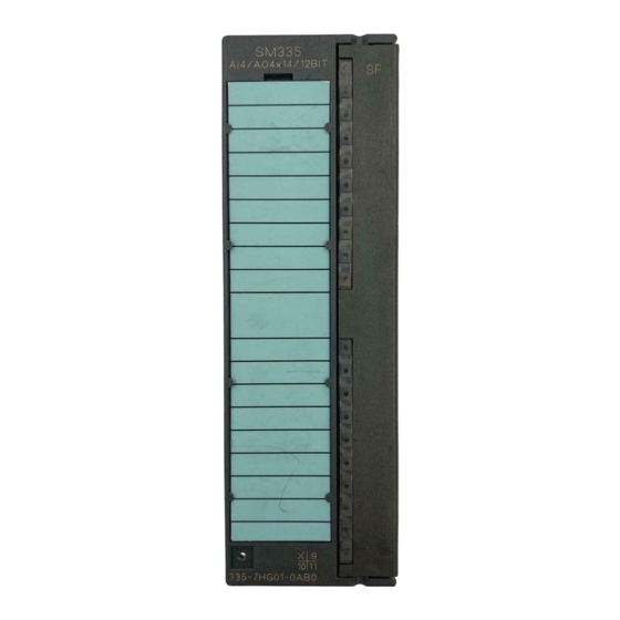
- Page 11 Properties and technical data of SM 335 Properties of SM 335 SM 355 is an I/O module for SIMATIC S7-300 and features the same general technical data as all of the other signal modules of SIMATIC S7-300. SM 335; AI4/AO4 14/12 Bit features the following properties.
- Page 12 – Comparator – Measuring only Interrupts / diagnostics ● Parameterizable diagnostics ● Parameterizable diagnostics interrupt ● Parameterizable cycle end interrupt (triggers a hardware interrupt on the CPU) SM 335 - High-speed analog mixed module for SIMATIC S7-300 Manual, 02/2009, A5E02409063-01...
- Page 13 Terminal diagram of SM 335 For information about the wiring of the inputs/outputs of SM 335, refer to chapter Wiring the inputs and outputs (Page 25) and to the Operating Instructions SIMATIC S7-300, Installation (http://support.automation.siemens.com/WW/view/en/13008499). The "X" imprint on the module identifies the version, in this case version 1. The version number is used to distinguish between products with the same order number.
- Page 14 Electrical isolation SM 335 contains a variety of different analog elements. The analog outputs are electrically isolated to the backplane bus of SIMATIC S7-300. All outputs are connected to the common potential M . The encoder supply output and the analog outputs are connected to common...
- Page 15 4 to 20 mA Input 0: Voltage ± 10 V Input 1: Voltage ± 10 V Input 2: Current ± 10 V Input 3: Current ± 10 V SM 335 - High-speed analog mixed module for SIMATIC S7-300 Manual, 02/2009, A5E02409063-01...
- Page 16 Diagnostics interrupt • Yes, parameterizable Diagnostics functions Yes, parameterizable Fault indication on the module for group • Yes, red LED errors Reading diagnostics information • Other UL/CSA/FM SM 335 - High-speed analog mixed module for SIMATIC S7-300 Manual, 02/2009, A5E02409063-01...
- Page 17 Wiring of the signal transducers For voltage measurement • Supported For current measurement • Not possible – As 2-wire transducer Supported – As 4-wire transducer Not possible For resistance measurement • SM 335 - High-speed analog mixed module for SIMATIC S7-300 Manual, 02/2009, A5E02409063-01...
- Page 18 Rated voltage 10 V Max. output current 25 mA Short-circuit-proof Operational limit (across temperature range) 0,2 % Temperature error 0.002 %/K Basic error of rated voltage 0.1% SM 335 - High-speed analog mixed module for SIMATIC S7-300 Manual, 02/2009, A5E02409063-01...
- Page 19 Short-circuit protection • Short-circuit current • 8 mA max. Connection of actuators For voltage output • Supported – 2-wire connection Not possible – 4-wire connection (measuring line) SM 335 - High-speed analog mixed module for SIMATIC S7-300 Manual, 02/2009, A5E02409063-01...
- Page 20 Max. 1 % at 400 Hz (across temperature range) Intrinsic error limit 0,005 % (operational limit at 25°C) Temperature error (0 to 60°C) ± 0.003 %/K Linearity error SM 335 - High-speed analog mixed module for SIMATIC S7-300 Manual, 02/2009, A5E02409063-01...
- Page 21 A description of those special modes is provided in chapter Special operating modes of SM 335 (Page 77). This chapter also describes how to switch to the special operating modes. SM 335 - High-speed analog mixed module for SIMATIC S7-300 Manual, 02/2009, A5E02409063-01...
- Page 22 To activate the free cycle, set up a cycle time of 0.5 ms for SM 335 in HW Config. The following figure shows the structure of the cycle time for the free cycle. Figure 1-3 Cycle time for the free cycle of SM 335 SM 335 - High-speed analog mixed module for SIMATIC S7-300 Manual, 02/2009, A5E02409063-01...
- Page 23 400 µs (200 µs + 1 x 200 µs + 4 x 0 µs). Deselection of the diagnostics functions does not have any effect on the cycle time. SM 335 - High-speed analog mixed module for SIMATIC S7-300 Manual, 02/2009, A5E02409063-01...
- Page 24 To activate the conditional cycle, set up a cycle time of 1 to 16 ms for SM 335 in HW Config. The following figure shows the structure of the cycle time for the conditional cycle. Figure 1-4 Cycle time for the conditional cycle of SM 335 SM 335 - High-speed analog mixed module for SIMATIC S7-300 Manual, 02/2009, A5E02409063-01...
- Page 25 Basics of the wiring of SM 335 You must install the SM 335 before wiring the analog I/O. Install SM 335 as any other I/O module of SIMATIC S7-300. Refer to the Operating Instructions SIMATIC S7-300, Hardware and Installation (http://support.automation.siemens.com/WW/view/en/13008499). Note the installation guidelines in these operating instructions.
- Page 26 It is helpful to terminate the analog inputs of SM 335 and the corresponding ground to a terminal block from which you can distribute the ground potential to the analog inputs. Installation This basically results in the following configuration: Figure 2-1 Wiring sensors SM 335 - High-speed analog mixed module for SIMATIC S7-300 Manual, 02/2009, A5E02409063-01...
- Page 27 You must take corresponding measures (depending on the encoder's potentials) to prevent the valid value from being exceeded. For more information, refer to the SIMATIC S7-300 Automation Systems, Module Data (http://support.automation.siemens.com/WW/view/en/8859629) Manual. If operated SM 335 in non-isolated mode, the common mode voltage between the encoder...
- Page 28 You should, therefore, disconnect the shield from the actuator's ground cable, or use an actuator whose ground cable is not connected to ground. SM 335 - High-speed analog mixed module for SIMATIC S7-300 Manual, 02/2009, A5E02409063-01...
- Page 29 ) with PIN 20 (24 V supply ground). Additional information For more information about the wiring of the interval counter input, refer to chapter Wiring the interval counter input (Page 72). SM 335 - High-speed analog mixed module for SIMATIC S7-300 Manual, 02/2009, A5E02409063-01...
- Page 30 Do not interconnect PIN 10 once again with PIN 6 or ground if using the 4-wire measurement shown in the previous figure. Such circuitry would develop a ground loop that is subject to interference coupling. SM 335 - High-speed analog mixed module for SIMATIC S7-300 Manual, 02/2009, A5E02409063-01...
- Page 31 Measured value Calculate the corrected analog measured value as follows: = corrected analog value Korr K = correction factor = analog value measured at the analog input SM 335 - High-speed analog mixed module for SIMATIC S7-300 Manual, 02/2009, A5E02409063-01...
- Page 32 Wiring the inputs and outputs 2.6 Adjusting the encoder supply SM 335 - High-speed analog mixed module for SIMATIC S7-300 Manual, 02/2009, A5E02409063-01...
- Page 33 (http://support.automation.siemens.com/WW/view/en/8859629) Manual describes how to insert the measuring range module into SM 335. The insert position of the measuring range module sets the measuring mode for the analog inputs (current/voltage measurement). SM 335 - High-speed analog mixed module for SIMATIC S7-300 Manual, 02/2009, A5E02409063-01...
- Page 34 You can use the output values to transfer analog values to SM 335. Those analog values are output at the analog outputs of SM 335; refer to the table of the output value of SM 335 in chapter Output values (Page 39) . SM 335 - High-speed analog mixed module for SIMATIC S7-300 Manual, 02/2009, A5E02409063-01...
- Page 35 Interval duration bits 8 to 15 *) or ***) ModAddr + Interval duration bits 0 to 7 *) or ***) *) Initial value **) set to factory default ***) current value SM 335 - High-speed analog mixed module for SIMATIC S7-300 Manual, 02/2009, A5E02409063-01...
- Page 36 (Page 60). You should preferably run the evaluation by calling OB 40 in order to ensure consistency of the measured value and of the number of end of cycle interrupts. SM 335 - High-speed analog mixed module for SIMATIC S7-300 Manual, 02/2009, A5E02409063-01...
- Page 37 Error code; refer to the table showing the meaning of bits 0, 1 and 2 in the return code of SM 335 1) Only one of the bits 5 and 6 can be set SM 335 - High-speed analog mixed module for SIMATIC S7-300 Manual, 02/2009, A5E02409063-01...
- Page 38 The "Comparator" mode was terminated because new parameters were transferred by means of SFC to SM 335. See also Principle of the special operating mode "Comparator" (Page 80) SM 335 - High-speed analog mixed module for SIMATIC S7-300 Manual, 02/2009, A5E02409063-01...
- Page 39 Representation of analog values of analog input channels (Page 40) and Representation of analog values for analog output channels (Page 42). SM 335 - High-speed analog mixed module for SIMATIC S7-300 Manual, 02/2009, A5E02409063-01...
- Page 40 -27652 93FC Undershoot range -1.176 V -11.759 V -2.940 V -11.76 mA -32512 8100 -32516 80FC Underflow -1.185 V -11.851 V -2.963 V -11.85 mA -32768 8000 SM 335 - High-speed analog mixed module for SIMATIC S7-300 Manual, 02/2009, A5E02409063-01...
- Page 41 -723.4 μV 1446.8 nA <4 mA FFFE Undershoot range Wire-break -18.446 mV -92.223 mV 18.448 μA (7FFF -225 FF00 <-18.446 mV <-92.223 mV <-18.448 μA -32768 8000 Underflow SM 335 - High-speed analog mixed module for SIMATIC S7-300 Manual, 02/2009, A5E02409063-01...
- Page 42 -10 V -27656 93F8 Undershoot range -10 V -27648 93F0 -10.006 V -32496 8110 -11.753 V -32504 8108 -11.753 V -32512 8100 Underflow (off-voltage and off-current) -32768 8000 SM 335 - High-speed analog mixed module for SIMATIC S7-300 Manual, 02/2009, A5E02409063-01...
- Page 43 HW Config of STEP 7. Also, position the measuring range modules of the module as required; refer to chapter Setting up the measuring range using the measuring range module (Page 15). SM 335 - High-speed analog mixed module for SIMATIC S7-300 Manual, 02/2009, A5E02409063-01...
- Page 44 (= short-circuit test at analog output) Wire-break check Reaction to CPU STOP Outputs have no current or voltage (OCV) Number of active channels *) Valid setting for the entire module SM 335 - High-speed analog mixed module for SIMATIC S7-300 Manual, 02/2009, A5E02409063-01...
- Page 45 From 0 V to + 10 V * The 0.5 ms setting in HW Config means: Free cycle The 1 to 16 ms setting in HW Config means: Conditional cycle SM 335 - High-speed analog mixed module for SIMATIC S7-300 Manual, 02/2009, A5E02409063-01...
- Page 46 ● 0 V (if "Outputs idle" was parameterized in HW Config) ● the most recently output analog value (if "Hold Last Value" was parameterized in HW Config). SM 335 - High-speed analog mixed module for SIMATIC S7-300 Manual, 02/2009, A5E02409063-01...
- Page 47 Data set 1 contains the dynamic parameters of SM 335 which you can modify. NOTICE The transfer always has to include the entire data set 1 (bytes 0 to 13). SM 335 - High-speed analog mixed module for SIMATIC S7-300 Manual, 02/2009, A5E02409063-01...
- Page 48 If you enable input diagnostics, SM 335 scans the analog inputs to detect common mode errors as well as measuring range overshoot and undershoot. If you enable output diagnostics, SM 335 scans the outputs to detect short-circuits. SM 335 - High-speed analog mixed module for SIMATIC S7-300 Manual, 02/2009, A5E02409063-01...
- Page 49 Fixed in the free and conditional cycle modes: 00 Wire-break check Monitoring time factor for the interval counter (refer to chapter Parameterizing the interval counter input of SM 335 (Page 74)) SM 335 - High-speed analog mixed module for SIMATIC S7-300 Manual, 02/2009, A5E02409063-01...
- Page 50 The process and diagnostics interrupt settings affect all module channels. Figure 3-3 Meaning of the bits in the byte for the output of interrupts and substitute values (DS1, byte 0) SM 335 - High-speed analog mixed module for SIMATIC S7-300 Manual, 02/2009, A5E02409063-01...
- Page 51 ● Byte 6 = analog output channel CH0 ● Byte 7 = analog output channel CH1 ● Byte 8 = analog output channel CH2 ● Byte 9 = analog output channel CH3 SM 335 - High-speed analog mixed module for SIMATIC S7-300 Manual, 02/2009, A5E02409063-01...
- Page 52 In the free and conditional cycle modes, this byte always has the value 00 Figure 3-4 Meaning of the bits in the " dynamic measuring cycle control" byte SM 335 - High-speed analog mixed module for SIMATIC S7-300 Manual, 02/2009, A5E02409063-01...
- Page 53 The parameters for the special operating mode "Comparator" can only be transferred by way of SFC 55 "WR_PARM" or SFB 53 "WRREC". NOTICE The transfer always has to include the entire data set DS1 (bytes 0 to 13). SM 335 - High-speed analog mixed module for SIMATIC S7-300 Manual, 02/2009, A5E02409063-01...
- Page 54 After the active comparator time has expired, SM 335 automatically returns to the "conditional cycle" or "free cycle" mode. Define the comparator time in milliseconds (1 = 1 ms, 2 = 2 ms, up to 0 = 256 ms). SM 335 - High-speed analog mixed module for SIMATIC S7-300 Manual, 02/2009, A5E02409063-01...
- Page 55 The comparator can also be monitored in the comparator check byte: The comparator check byte has the following structure: Figure 3-7 Comparator check byte for the special mode "Comparator" SM 335 - High-speed analog mixed module for SIMATIC S7-300 Manual, 02/2009, A5E02409063-01...
- Page 56 ● Bit i = 0: the old analog value is retained You can set up to 3 bits. The analog values are output until a new value is written to the output. SM 335 - High-speed analog mixed module for SIMATIC S7-300 Manual, 02/2009, A5E02409063-01...
- Page 57 Used as in the free and conditional cycle modes ( refer to chapter SM 335 parameters for the free and conditional cycle modes (Page 49), table of the SM 335 parameters in data set 1 (DS1) SM 335 - High-speed analog mixed module for SIMATIC S7-300 Manual, 02/2009, A5E02409063-01...
- Page 58 Meaning of the bits in the " dynamic measuring cycle control" byte Bit 4 in the "Dynamic measuring cycle control" (comparator mode) byte must be set to "0". SM 335 - High-speed analog mixed module for SIMATIC S7-300 Manual, 02/2009, A5E02409063-01...
- Page 59 You can view all diagnostics data of SM 335 by calling SFC 59. Chapter Structure of the diagnostics data for SM 335 (Page 61) provides a description of the syntax of diagnostics data. SM 335 - High-speed analog mixed module for SIMATIC S7-300 Manual, 02/2009, A5E02409063-01...
- Page 60 The comparator time is set in byte 10 of the parameterization data set DS 1 Measured value low byte of Comparator 2 Measured value high byte of Comparator 2 1) Bytes 9 to 11 are not used for comparator mode 0 SM 335 - High-speed analog mixed module for SIMATIC S7-300 Manual, 02/2009, A5E02409063-01...
- Page 61 Channel-specific diagnostics byte for analog output CH0 Channel-specific diagnostics byte for analog output CH1 Channel-specific diagnostics byte for analog output CH2 Channel-specific diagnostics byte for analog output CH3 SM 335 - High-speed analog mixed module for SIMATIC S7-300 Manual, 02/2009, A5E02409063-01...
- Page 62 Internal error Bit 1 is set in module diagnostics byte 0 if SM 335 indicates one of the following errors: ● Watchdog ● EEPROM error ● ADC/DAC error SM 335 - High-speed analog mixed module for SIMATIC S7-300 Manual, 02/2009, A5E02409063-01...
- Page 63 SFC 55 "WR_PARM" or SFB 53 "WRREC". 3.4.4 Module diagnostics byte 1 Structure Module diagnostics byte 1 always contains the fixed value 35 SM 335 - High-speed analog mixed module for SIMATIC S7-300 Manual, 02/2009, A5E02409063-01...
- Page 64 , and the counter input is set to FF FF FF 3.4.6 Module diagnostics byte 3 Structure Module diagnostics bytes 3 and 2 indicate error states. Figure 3-13 Module diagnostics byte 3 SM 335 - High-speed analog mixed module for SIMATIC S7-300 Manual, 02/2009, A5E02409063-01...
- Page 65 Image of changes to channel-specific diagnostic data Note Channel-specific faults at the analog output channels CH0 to CH3 or output in the diagnostics view of HW Config as channels CH4 to CH7. SM 335 - High-speed analog mixed module for SIMATIC S7-300 Manual, 02/2009, A5E02409063-01...
- Page 66 The measured value at the input is checked for overflow (bit 7) and underflow (bit 6). The corresponding bit is set if the analog value is in overflow or underflow state. SM 335 - High-speed analog mixed module for SIMATIC S7-300 Manual, 02/2009, A5E02409063-01...
- Page 67 SM 335 sets the bits in the channel-specific diagnostics bytes of the outputs after it has detected a short-circuit or a parameterization error at the corresponding analog output. Figure 3-16 Channel-specific diagnostics byte for the analog output SM 335 - High-speed analog mixed module for SIMATIC S7-300 Manual, 02/2009, A5E02409063-01...
- Page 68 Data exchange with SM 335 3.4 Evaluating the diagnostics data of SM 335 SM 335 - High-speed analog mixed module for SIMATIC S7-300 Manual, 02/2009, A5E02409063-01...
- Page 69 You can also record the signals of simple rotary encoders and determine the speed based on the interval period. The number of intervals per time unit or the intervals for distance measurements can also be used to measure velocity. SM 335 - High-speed analog mixed module for SIMATIC S7-300 Manual, 02/2009, A5E02409063-01...
- Page 70 1 until the next positive edge at cyclic intervals of 0.5 μs. We refer to this counter as the interval duration counter. SM 335 - High-speed analog mixed module for SIMATIC S7-300 Manual, 02/2009, A5E02409063-01...
- Page 71 The interval duration counter returns a 3-byte count value. Those 3 bytes can be used to represent values up to FF FF FF (decimal 16777215). The lower limit frequency is derived accordingly for N = 1: SM 335 - High-speed analog mixed module for SIMATIC S7-300 Manual, 02/2009, A5E02409063-01...
- Page 72 The cam disc is mounted on a rotary shaft, for example, on the extruder worm of an injection molding machine. Figure 4-2 Wiring the encoder to the interval counter input SM 335 - High-speed analog mixed module for SIMATIC S7-300 Manual, 02/2009, A5E02409063-01...
- Page 73 To provide a reference potential for the interval counter input, it is sufficient to connect the input to the 24 V load voltage which is connected to ground potential; refer to the SIMATIC S7-300, Hardware and Installation (http://support.automation.siemens.com/WW/view/en/13008499) Operating Instructions. SM 335 - High-speed analog mixed module for SIMATIC S7-300 Manual, 02/2009, A5E02409063-01...
- Page 74 Special case: The '0’ value is equivalent by default to 8.388 seconds. Examples: ● Byte 13 (DS1) = 1 → monitoring time = 0,032765625 seconds ● Byte 13 (DS1) = 2 → monitoring time = 0.06553125 seconds SM 335 - High-speed analog mixed module for SIMATIC S7-300 Manual, 02/2009, A5E02409063-01...
- Page 75 The internal duration is measured once again. The interval counter is incremented again by the count of "1" if a valid interval is measured at the next pulse input. SM 335 - High-speed analog mixed module for SIMATIC S7-300 Manual, 02/2009, A5E02409063-01...
- Page 76 The interval between two pulses had a duration of 43000 x 0.5 μs. The rotational speed of the extruder worm is then calculated as follows: SM 335 - High-speed analog mixed module for SIMATIC S7-300 Manual, 02/2009, A5E02409063-01...
- Page 77 In the special mode "Measuring Only", SM 335 performs continuous measurements without updating the analog outputs. This facilitates particularly short cycle times for the recording of analog inputs. SM 335 - High-speed analog mixed module for SIMATIC S7-300 Manual, 02/2009, A5E02409063-01...
- Page 78 To enable the special mode "Measuring Only", you must transfer all parameters for SM 335 and set bit 6 and 7 in byte 11: Figure 5-2 Dynamic measuring cycle control for the special mode "Measuring Only" SM 335 - High-speed analog mixed module for SIMATIC S7-300 Manual, 02/2009, A5E02409063-01...
- Page 79 "conditional cycle" or "free cycle" • mode For more information about the parameterization for the "Comparator" mode, refer to chapter SM 335 parameters for the special mode "Comparator" (Page 53). SM 335 - High-speed analog mixed module for SIMATIC S7-300 Manual, 02/2009, A5E02409063-01...
- Page 80 Comparator 1 does not generate a process interrupt, does not output any analog values, and changes over to Comparator 2. Comparator 1 The following figure shows how Comparator 1 works: Figure 5-3 Operating principle of Comparator 1 SM 335 - High-speed analog mixed module for SIMATIC S7-300 Manual, 02/2009, A5E02409063-01...
- Page 81 Comparator 1 does not operate at the cycle time time of 1 ms. Comparator 2 The following figure shows how Comparator 2 works: Figure 5-4 Operating principle of Comparator 2 SM 335 - High-speed analog mixed module for SIMATIC S7-300 Manual, 02/2009, A5E02409063-01...
- Page 82 SM 33 has been started. Remedy: Do not read the values from the analog inputs until the next end of cycle interrupt has been cleared. SM 335 - High-speed analog mixed module for SIMATIC S7-300 Manual, 02/2009, A5E02409063-01...
- Page 83 Message by means of return code of SM 335; refer to the table in chapter Input values (Page 35) for information about the bits in the return code of SM 335. SM 335 - High-speed analog mixed module for SIMATIC S7-300 Manual, 02/2009, A5E02409063-01...
- Page 84 SM 335. Using this analog output you can directly control the drive for the form/mold motion. This method lets you achieve fast closing motions and reproducible, high-speed braking actions. SM 335 - High-speed analog mixed module for SIMATIC S7-300 Manual, 02/2009, A5E02409063-01...
- Page 85 The set comparator time is reported in the local data of OB 40, provided SM 335 has generated a corresponding process interrupt. (refer to table 'Interrupt table triggered by the comparator' in chapter Hardware interrupt (Page 60). SM 335 - High-speed analog mixed module for SIMATIC S7-300 Manual, 02/2009, A5E02409063-01...
- Page 86 The comparator can also be monitored in the comparator check byte: The comparator check byte has the following structure: Figure 5-8 Comparator check byte for the special mode "Comparator" SM 335 - High-speed analog mixed module for SIMATIC S7-300 Manual, 02/2009, A5E02409063-01...
- Page 87 The measured value of Comparators 2 can be read from the local data of OB 40. (bytes 10 and 11, refer to the 'Interrupt triggered by the comparator' section in chapter Hardware interrupt (Page 60). SM 335 - High-speed analog mixed module for SIMATIC S7-300 Manual, 02/2009, A5E02409063-01...
- Page 88 (T <0.5 ms). After time has expired, SM 335 returns to the previously parameterized operating mode. SM 335 - High-speed analog mixed module for SIMATIC S7-300 Manual, 02/2009, A5E02409063-01...
- Page 89 Assigned as defined in chapter SM 335 parameters for the free and conditional cycle modes (Page 49) Dynamic measuring cycle control Assigned as defined in chapter SM 335 parameters for the free and conditional cycle modes (Page 49) SM 335 - High-speed analog mixed module for SIMATIC S7-300 Manual, 02/2009, A5E02409063-01...
- Page 90 ’1’. You can achieve a measuring cycle time < 0.5 ms by disabling three analog inputs. SM 335 - High-speed analog mixed module for SIMATIC S7-300 Manual, 02/2009, A5E02409063-01...
- Page 91 Advantage of the diagnostics interrupt OB 82 is called automatically if you enabled the diagnostics interrupt. OB 82 returns the module start address in the local data. SM 335 - High-speed analog mixed module for SIMATIC S7-300 Manual, 02/2009, A5E02409063-01...
- Page 92 SM 335 reports a wire-break in the 4 to 20 mA range in the current to be measured is less than 1.185 mA. This action triggers a diagnostic message and the ID 7FFF SM 335 - High-speed analog mixed module for SIMATIC S7-300 Manual, 02/2009, A5E02409063-01...
- Page 93 (e.g. wire break), which, however, disable diagnostics interrupts. A change to diagnostics data always leads to a change of data set 1 which can always be read, independent of the parameterization. SM 335 - High-speed analog mixed module for SIMATIC S7-300 Manual, 02/2009, A5E02409063-01...
- Page 94 (refer to chapter Structure of the diagnostics data for SM 335 (Page 61)) You can react to the fault in your program with the help of the diagnostics data. SM 335 - High-speed analog mixed module for SIMATIC S7-300 Manual, 02/2009, A5E02409063-01...
- Page 95 3. If a bit is set, follow the arrows again from this bit and check which one of the bits is set, and so forth. 4. The table below provides an error description for the corresponding bit. Figure 6-1 Error tree of SM 335 SM 335 - High-speed analog mixed module for SIMATIC S7-300 Manual, 02/2009, A5E02409063-01...
- Page 96 Verify the correct position of the module diagnostics byte 2 bit 0 or missing. measuring range module and check whether this position agrees with the parameter settings. SM 335 - High-speed analog mixed module for SIMATIC S7-300 Manual, 02/2009, A5E02409063-01...
- Page 97 SM 335. SM335 reports the channel which has incorrect analog output x bit 0 channel-specific parameters. Channel-specific diagnostics byte Analog input x bit 0 SM 335 - High-speed analog mixed module for SIMATIC S7-300 Manual, 02/2009, A5E02409063-01...
- Page 98 Troubleshooting 6.5 Troubleshooting SM 335 - High-speed analog mixed module for SIMATIC S7-300 Manual, 02/2009, A5E02409063-01...
- Page 99 Measuring line (positive / negative) Reference potential of the analog measuring circuit Organization block Group error Error LED, System function block System function Signal module Common Mode Voltage SM 335 - High-speed analog mixed module for SIMATIC S7-300 Manual, 02/2009, A5E02409063-01...
- Page 100 List of abbreviations A.1 List of abbreviations SM 335 - High-speed analog mixed module for SIMATIC S7-300 Manual, 02/2009, A5E02409063-01...
- Page 101 A transfer medium that interconnects several nodes. Data may be transferred in serial or parallel mode, using electrical or fiber-optic conductors. Bus segment Self-contained part of a bus system. Bus segments are coupled by means of → Repeater. SM 335 - High-speed analog mixed module for SIMATIC S7-300 Manual, 02/2009, A5E02409063-01...
- Page 102 Module diagnostics function report errors to the → CPU by means of diagnostics interrupts. The CPU operating system calls OB 82 when a diagnostics interrupt is generated. SM 335 - High-speed analog mixed module for SIMATIC S7-300 Manual, 02/2009, A5E02409063-01...
- Page 103 The permissible input delay is determined by the line length between the encoder and the module. Unshielded encoder supply lines of a grater length (more than 100 m) require a long delay setting. SM 335 - High-speed analog mixed module for SIMATIC S7-300 Manual, 02/2009, A5E02409063-01...
- Page 104 Organization block OBs form the interface between the CPU operating system and the user program. The sequential order of user program execution is defined in the organization blocks. SM 335 - High-speed analog mixed module for SIMATIC S7-300 Manual, 02/2009, A5E02409063-01...
- Page 105 → System Function Signal module Signal modules (SMs) form the interface between the process and the automation system. These are available as digital and analog input/output and IO modules. SM 335 - High-speed analog mixed module for SIMATIC S7-300 Manual, 02/2009, A5E02409063-01...
- Page 106 . A wirebreak check is used to monitor line continuity between the encoder and input, or between the actuator and output. The module detects a wirebreak based on a current flow at the appropriately programmed input/output. SM 335 - High-speed analog mixed module for SIMATIC S7-300 Manual, 02/2009, A5E02409063-01...
- Page 107 OB 40, 60 Position, 4 Operating mode Conditional cycle, 24 Free cycle, 22 Order number 6ES7335- 7HG02-0AB0, 11 Error description, 96 Output values, 34 Error tree, 95 Installation, 39 SM 335 - High-speed analog mixed module for SIMATIC S7-300 Manual, 02/2009, A5E02409063-01...
- Page 108 Module diagnostics byte 3, 64 Technical data, 16 of the analog inputs, 17 Of the analog outputs, 19 Of the interval counter, 20 Terminal diagram, 13 Training Centers, 6 SM 335 - High-speed analog mixed module for SIMATIC S7-300 Manual, 02/2009, A5E02409063-01...