Table of Contents
Advertisement
Quick Links
HPE ProLiant BL460c Gen9 Server
Blade
User Guide
Abstract
This document is for the person who installs, administers, and troubleshoots servers and storage systems. Hewlett Packard Enterprise
assumes you are qualified in the servicing of computer equipment and trained in recognizing hazards in products with hazardous energy
levels.
Part Number: 768826-005
March 2017
Edition: 5
Advertisement
Table of Contents

Related Manuals for HP proliant bl460c gen9


Summary of Contents for HP proliant bl460c gen9
-
Page 1: User Guide
HPE ProLiant BL460c Gen9 Server Blade User Guide Abstract This document is for the person who installs, administers, and troubleshoots servers and storage systems. Hewlett Packard Enterprise assumes you are qualified in the servicing of computer equipment and trained in recognizing hazards in products with hazardous energy levels. - Page 2 © Copyright 2014, 2017 Hewlett Packard Enterprise Development LP The information contained herein is subject to change without notice. The only warranties for Hewlett Packard Enterprise products and services are set forth in the express warranty statements accompanying such products and services. Nothing herein should be construed as constituting an additional warranty.
-
Page 3: Table Of Contents
Contents Component identification ........................6 Front panel components ............................6 Front panel LEDs and buttons ..........................7 Front panel LED power fault codes ....................... 7 Serial label pull tab information ........................8 Drive numbering ............................... 8 Hot-plug drive LED definitions ..........................9 NVMe SSD components ............................ - Page 4 General DIMM slot population guidelines ....................47 Identifying the processor type........................48 Installing a DIMM ............................49 HP Trusted Platform Module option ........................50 Installing the Trusted Platform Module board ....................50 Retaining the recovery key/password......................52 Enabling the Trusted Platform Module ......................52 Cabling ..............................
- Page 5 System battery replacement ........................ 70 Regulatory information ......................... 72 Safety and regulatory compliance .......................... 72 Belarus Kazakhstan Russia marking ........................72 Turkey RoHS material content declaration ......................73 Ukraine RoHS material content declaration ......................73 Warranty information .............................. 73 Electrostatic discharge ......................... 74 Preventing electrostatic discharge .........................
-
Page 6: Component Identification
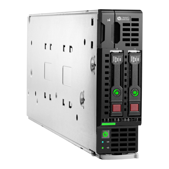
Component identification Front panel components Item Description Serial label pull tab HPE c-Class Blade SUV connector* (behind the serial label pull tab) Drive bay 2 Drive bay 1 Server blade release lever Server blade release button *The SUV connector and the c-Class Blade SUV Cable are used for some server blade configuration and diagnostic procedures. -
Page 7: Front Panel Leds And Buttons
Front panel LEDs and buttons Item Description Status Health LED Solid green = Normal Flashing green (1 flash per second) = iLO is rebooting Flashing amber = System degraded Flashing red (1 flash per second) = System critical If the health LED indicates a degraded or critical state, review the system IML ("Integrated Management Log"... -
Page 8: Serial Label Pull Tab Information
Subsystem Front panel LED behavior 1 flash System board 2 flashes Processor 3 flashes Memory 4 flashes Riser board PCIe slots 5 flashes FlexibleLOM 6 flashes Removable HPE Flexible Smart Array controller/Smart SAS HBA controller 7 flashes System board PCIe slots 8 flashes Power backplane or storage backplane 9 flashes... -
Page 9: Hot-Plug Drive Led Definitions
Hot-plug drive LED definitions Item Status Definition Locate Solid blue The drive is being identified by a host application. Flashing blue The drive carrier firmware is being updated or requires an update. Activity ring Rotating green Drive activity No drive activity Do not remove Solid white Do not remove the drive. -
Page 10: Nvme Ssd Components
NVMe SSD components Item Component Status Definition Release lever Ejects the NVMe drive carrier from the cage. — Activity ring LED Rotating green Drive activity No drive activity Do Not Remove Solid white Drive is powered on, and configured in system. Do not remove the drive. -
Page 11: System Board Components
System board components Item Description System battery Solid state device connector (M.2) Processor 2 DIMM slots (8) Processor 1 DIMM slots (8) SAS/SATA controller or NVMe pass-through board connector Mezzanine connector 1 (Type A mezzanine only) Mezzanine connector 2 (Type A or Type B mezzanine) Enclosure connector MicroSD card slot FlexibleLOM connectors (2) -
Page 12: Mezzanine Connector Definitions
Position Default Function Off = Power-on password is enabled. On = Power-on password is disabled. Off = No function. On = ROM reads system configuration as invalid. Off = Set default boot mode to UEFI. On = Set default boot mode to legacy. -
Page 13: Suv Cable Connectors
The arrow points to the front of the server blade. SUV cable connectors CAUTION: Before disconnecting the SUV cable from the connector, always squeeze the release buttons on the sides of the connector. Failure to do so can result in damage to the equipment. -
Page 14: Operations
Operations Power up the server blade The Onboard Administrator initiates an automatic power-up sequence when the server blade is installed. If the default setting is changed, use one of the following methods to power up the server blade: • Use a virtual power button selection through iLO. •... -
Page 15: Remove The Server Blade
• Use the Onboard Administrator GUI to initiate a shutdown: Select the Enclosure Information tab. In the Device Bays item, select the Overall checkbox. From the Virtual Power menu, initiate a shutdown of applications and the OS: — For a controlled shutdown, select Momentary Press. —... -
Page 16: Install The Access Panel
Slide the access panel towards the rear of the server blade, and then lift to remove the panel. Install the access panel Place the access panel on top of the server blade. Slide the access panel forward until it clicks into place. Remove the DIMM baffles The server contains two DIMM baffles. -
Page 17: Install The Dimm Baffles
DIMM baffle (right side) DIMM baffle (left side) Install the DIMM baffles The server contains two DIMM baffles. Power down the server blade (on page 14). Remove the server blade (on page 15). Place the server blade on a flat, level work surface. Operations 17... - Page 18 Remove the access panel (on page 15). Install the DIMM baffle. DIMM baffle (right side) DIMM baffle (left side) Install the access panel (on page 16). Install the server blade (on page 28). Power up the server blade (on page 14). Operations 18...
-
Page 19: Remove The Direct Connect Sata Cable
Remove the direct connect SATA cable Power down the server blade (on page 14). Remove the server blade (on page 15). Place the server blade on a flat, level work surface. Remove the access panel (on page 15). Remove the direct connect SATA cable. Press in the latch on the connector. -
Page 20: Remove The Mezzanine Assembly
Route and secure the cable onto the right DIMM baffle. Remove the mezzanine assembly Power down the server blade (on page 14). Remove the server blade (on page 15). Place the server blade on a flat, level work surface. Remove the access panel (on page 15). Remove the mezzanine assembly. -
Page 21: Install The Flexiblelom
Remove the access panel (on page 15). Remove the mezzanine assembly (on page 20). Use the FlexibleLOM handle to remove the FlexibleLOM from the system board. Install the FlexibleLOM Power down the server blade (on page 14). Remove the server blade (on page 15). Place the server blade on a flat, level work surface. -
Page 22: Remove The Storage Controller/Nvme Pass-Through Board
Power up the server blade (on page 14). Remove the storage controller/NVMe pass-through board Back up all server blade data. Power down the server blade (on page 14). Remove the server blade (on page 15). Place the server blade on a flat, level work surface. Remove the access panel (on page 15). -
Page 23: Remove A Drive
Remove a drive Back up all server blade data on the drive. Remove the drive. Install the front panel/drive cage assembly Power down the server blade (on page 14). Remove the server blade (on page 15). Place the server blade on a flat, level work surface. Remove the access panel (on page 15). -
Page 24: Remove The Front Panel/Drive Cage Assembly
Install the direct connect SATA cable (on page 19). Install the access panel (on page 16). Install the server blade (on page 28). Power up the server blade (on page 14). Remove the front panel/drive cage assembly Power down the server blade (on page 14). Remove the server blade (on page 15). -
Page 25: Setup
Setup Overview Installation of a server blade requires the following steps: Install and configure a BladeSystem c-Class enclosure. Install any server blade options. Install interconnect modules in the enclosure. Connect the interconnect modules to the network. Install a server blade. Complete the server blade configuration. -
Page 26: Interconnect Bay Numbering And Device Mapping
Interconnect bay numbering and device mapping • HPE BladeSystem c7000 Enclosure To support network connections for specific signals, install an interconnect module in the bay corresponding to the FlexibleLOM or mezzanine signals. Server blade signal Interconnect Interconnect bay labels 1 and 2 FlexibleLOM 3 and 4 Mezzanine 1... -
Page 27: Connecting To The Network
• HPE BladeSystem c3000 Enclosure Server blade Interconnect Interconnect Notes signal bay number bay label — FlexibleLOM Four-port cards connect to bay 2. Mezzanine 1 3 and 4 • Mezzanine 2 Four-port cards • Ports 1 and 3 connect to bay 3. •... -
Page 28: Install The Server Blade
Two types of interconnect modules are available for BladeSystem c-Class enclosures: Pass-Thru modules and switch modules. For more information about interconnect module options, see the Hewlett Packard Enterprise website (http://www.hpe.com/servers/blades/interconnects). IMPORTANT: To connect to a network with a Pass-Thru module, always connect the Pass-Thru module to a network device that supports Gigabit or 10 Gb speed, depending on the corresponding Pass-Thru model. -
Page 29: Completing The Configuration
Remove the enclosure connector cover. Retain the blank for future use. Install the server blade. Completing the configuration To complete the server blade and BladeSystem configuration, see the overview card that ships with the enclosure. Setup 29... -
Page 30: Hardware Options Installation
Hardware options installation Introduction If more than one option is being installed, read the installation instructions for all the hardware options and identify similar steps to streamline the installation process. WARNING: To reduce the risk of personal injury from hot surfaces, allow the drives and the internal system components to cool before touching them. -
Page 31: Nvme Ssd Option
Install the drive. Determine the status of the drive from the drive LED definitions ("Hot-plug drive LED definitions" on page 9). NVMe SSD option CAUTION: To prevent improper cooling and thermal damage, do not operate the server blade or the enclosure unless all drive and device bays are populated with either a component or a blank. -
Page 32: Storage Controller/Nvme Pass-Through Board Options
Determine the status of the drive from the LEDs ("NVMe SSD components" on page 10). Storage controller/NVMe pass-through board options To install the component: Back up all server blade data. Power down the server blade (on page 14). Remove the server blade (on page 15). Place the server blade on a flat, level work surface. -
Page 33: Smart Storage Battery Option
Push the handle down into the closed position to fully seat the storage controller/NVMe pass-through board. Install the access panel (on page 16). Install the server blade (on page 28). Power up the server blade (on page 14). Smart Storage Battery option To install the component: Power down the server blade (on page 14). - Page 34 Install the Smart Storage Battery on the DIMM baffle. Route the cable on the DIMM baffle. Align and install the DIMM baffle. Hardware options installation 34...
-
Page 35: Mezzanine Card Option
Press down on the cable connector to fully seat the Smart Storage Battery cable connector to the system board. If removed, install the direct connect SATA cable ("Install the direct connect SATA cable" on page 19). If removed, install the internal USB drive. To locate the internal USB connector, see "System board components (on page 11)."... - Page 36 Remove the mezzanine assembly. Align the mezzanine card with the guide pins on the mezzanine assembly. Hardware options installation 36...
-
Page 37: M.2 Enablement Option
Install the mezzanine card in the mezzanine assembly, and then tighten the mezzanine card screws to secure the card to the mezzanine assembly. Align the mezzanine assembly with the guide pins on the system board, and then install the mezzanine assembly on the system board. Press down firmly on the mezzanine assembly handles, and then close the mezzanine assembly latch. -
Page 38: Installing A Processor
Remove the access panel (on page 15). Do one of the following: Remove the storage controller/NVMe pass-through board (on page 22). Remove the direct connect SATA cable (on page 19). Remove all DIMM baffles ("Remove the DIMM baffles" on page 16). Remove the front panel/drive cage assembly (on page 24). - Page 39 CAUTION: To prevent possible server blade overheating, always populate processor socket 2 with a processor and a heatsink or a processor socket cover and a heatsink blank. CAUTION: To prevent damage to electrical components, properly ground the server blade before beginning any installation procedure. Improper grounding can cause ESD. IMPORTANT: Processor socket 1 must be populated at all times or the server blade does not function.
- Page 40 Open each of the processor locking levers in the order indicated in the following illustration, and then open the processor retaining bracket. Remove the clear processor socket cover. Retain the processor socket cover for future use. CAUTION: THE PINS ON THE SYSTEM BOARD ARE VERY FRAGILE AND EASILY DAMAGED.
- Page 41 Install the processor. Verify that the processor is fully seated in the processor retaining bracket by visually inspecting the processor installation guides on either side of the processor. THE PINS ON THE SYSTEM BOARD ARE VERY FRAGILE AND EASILY DAMAGED. Close the processor retaining bracket.
-
Page 42: Memory Options
Remove the thermal interface protective cover from the heatsink. CAUTION: To avoid damage to the system board, processor socket, and screws, do not overtighten the heatsink screws. Using a T-15 screwdriver, install the heatsink. Install all DIMM baffles ("Install the DIMM baffles"... -
Page 43: Memory-Processor Compatibility Information
IMPORTANT: This server blade does not support mixing LRDIMMs and RDIMMs. Attempting to mix any combination of these DIMMs can cause the server to halt during BIOS initialization. The memory subsystem in this server blade can support LRDIMMs or RDIMMs: •... - Page 44 Operating memory speed is a function of rated DIMM speed, the number of DIMMs installed per channel, processor model, and the speed selected in the BIOS/Platform Configuration (RBSU) of the UEFI System Utilities ("UEFI System Utilities" on page 62). Populated DIMM speed with Intel Xeon E5-2600 v3 processors installed Type Rank 1 DIMM per channel...
-
Page 45: Smartmemory
SmartMemory SmartMemory authenticates and unlocks certain features available only on Qualified memory and verifies whether installed memory has passed Hewlett Packard Enterprise qualification and test processes. Qualified memory is performance-tuned for ProLiant and BladeSystem servers and provides future enhanced support through Active Health and manageability software. Memory subsystem architecture The memory subsystem in this server blade is divided into channels. -
Page 46: Dimm Identification
DIMM identification To determine DIMM characteristics, see the label attached to the DIMM and refer to the following illustration and table. Item Description Definition Capacity 8 GB 16 GB 32 GB 64 GB 128 GB Rank 1R = Single-rank 2R = Dual-rank 4R = Quad-rank 8R = Octal-rank Data width on DRAM... -
Page 47: General Dimm Slot Population Guidelines
Advanced Memory Protection options are configured in the BIOS/Platform Configuration (RBSU). If the requested AMP mode is not supported by the installed DIMM configuration, the server blade boots in Advanced ECC mode. For more information, see the HPE UEFI System Utilities User Guide for HPE ProLiant Gen9 Servers on the Hewlett Packard Enterprise website (http://www.hpe.com/info/ProLiantUEFI/docs). -
Page 48: Identifying The Processor Type
• When two processors are installed, install the DIMMs in sequential alphabetical order balanced between the two processors: P1-A, P2-A, P1-B, P2-B, P1-C, P2-C, and so forth. • When single-rank, dual-rank, and quad-rank DIMMs are populated for two DIMMs per channel, always populate the higher number rank DIMM first (starting from the farthest slot). -
Page 49: Installing A Dimm
Installing a DIMM CAUTION: To avoid damage to the hard drives, memory, and other system components, the air baffle, drive blanks, and access panel must be installed when the server is powered up. CAUTION: To avoid damage to the hard drives, memory, and other system components, be sure to install the correct DIMM baffles for your server model. -
Page 50: Hp Trusted Platform Module Option
HP Trusted Platform Module option For more information about product features, specifications, options, configurations, and compatibility, see the product QuickSpecs on the Hewlett Packard Enterprise website (http://www.hpe.com/info/qs). Use these instructions to install and enable a TPM on a supported server blade. This procedure includes three sections: Installing the Trusted Platform Module board. - Page 51 Remove the storage controller/NVMe pass-through board (on page 22). Remove the direct connect SATA cable (on page 19). If installed, remove the internal USB drive. To locate the internal USB connector, see "System board components (on page 11)." Remove the DIMM baffle ("Remove the DIMM baffles"...
-
Page 52: Retaining The Recovery Key/Password
OS application TPM settings. For more information on firmware updates and hardware procedures, see the HP Trusted Platform Module Best Practices White Paper on the Hewlett Packard Enterprise Support Center website (http://www.hpe.com/support/hpesc). -
Page 53: Cabling
Cabling Cabling resources Cabling configurations and requirements vary depending on the product and installed options. For more information about product features, specifications, options, configurations, and compatibility, see the product QuickSpecs on the Hewlett Packard Enterprise website (http://www.hpe.com/info/qs). HPE Smart Storage Battery cabling Direct connect SATA cabling Cabling 53... -
Page 54: Using The Hpe C-Class Blade Suv Cable
Using the HPE c-Class Blade SUV Cable The c-Class Blade SUV Cable enables the user to perform server blade administration, configuration, and diagnostic procedures by connecting video and USB devices directly to the server blade. For SUV cable connectors, see "SUV cable connectors (on page 13)." Connecting locally to a server blade with video and USB devices Use the SUV cable to connect a monitor and any of the following USB devices:... -
Page 55: Accessing Local Media Devices
Item Description USB mouse USB keyboard c-Class Blade SUV Cable Accessing local media devices Use the following configuration when configuring a server blade or loading software updates and patches from a USB CD/DVD-ROM. Use a USB hub when connecting a USB CD-ROM drive to the server blade. The USB connectors on the SUV cable do not support devices that require greater than a 500mA power source. -
Page 56: Troubleshooting
Troubleshooting Troubleshooting resources The HPE ProLiant Gen9 Troubleshooting Guide, Volume I: Troubleshooting provides procedures for resolving common problems and comprehensive courses of action for fault isolation and identification, issue resolution, and software maintenance on ProLiant servers and server blades. To view the guide, select a language: •... -
Page 57: Software And Configuration Utilities
Scripting Toolkit for Windows and Linux (on page 61) Online and Offline Service Pack for ProLiant (on page 61) Online and Offline HP Smart Update Manager (on page 61) Offline HPE UEFI System Utilities ("UEFI System Utilities" on page 62) -
Page 58: Ilo Restful Api Support
The Active Health System provides: • Continuous health monitoring of over 1600 system parameters • Logging of all configuration changes • Consolidated health and service alerts with precise time stamps • Agentless monitoring that does not affect application performance The Agentless Management Service is available in the SPP, which can be downloaded from the Hewlett Packard Enterprise website (http://www.hpe.com/servers/spp/download). -
Page 59: Hpe Ilo
automatic, secure submission of hardware event notifications to Hewlett Packard Enterprise, which will initiate a fast and accurate resolution, based on your product’s service level. Notifications can be sent to your authorized Hewlett Packard Enterprise Channel Partner for onsite service, if configured and available in your country. -
Page 60: Intelligent Provisioning
Intelligent Provisioning Intelligent Provisioning is a single-server deployment tool embedded in ProLiant Gen8 and later servers. Intelligent Provisioning simplifies ProLiant server setup and provides a reliable and consistent way to deploy ProLiant server configurations: • Intelligent Provisioning prepares the system for installing "off-the-shelf" and Hewlett Packard Enterprise branded versions of operating system software and integrates optimized ProLiant server support software. -
Page 61: Scripting Toolkit For Windows And Linux
The SPP is a comprehensive systems software (drivers and firmware) solution delivered as a single package with major server releases. This solution uses HP SUM as the deployment tool and is tested on all supported ProLiant servers including ProLiant Gen8 and later servers. -
Page 62: Uefi System Utilities
ProLiant servers and network-based targets, such as iLOs, OAs, and VC Ethernet and Fibre Channel modules. For more information about HP SUM, see the product page on the Hewlett Packard Enterprise website (http://www.hpe.com/servers/hpsum). To download HP SUM, see the Hewlett Packard Enterprise website (http://www.hpe.com/servers/hpsum/download). -
Page 63: Flexible Boot Control
Flexible boot control This feature enables you to do the following: • Add Boot Options: Browse all FAT16 and FAT32 file systems. To add a new UEFI boot option, select an X64 UEFI application with an .EFI extension. For example, adding an OS boot loader or other UEFI application as a new UEFI boot option. The new boot option is appended to the boot-order list. -
Page 64: Embedded Uefi Shell
A physically present user can customize the certificates embedded in the UEFI BIOS by adding or removing their own certificates. When Secure Boot is enabled, the System Maintenance Switch does not restore all manufacturing defaults when set to the ON position. For security reasons, the following are not restored to defaults when the System Maintenance Switch is in the ON position: •... -
Page 65: Utilities And Features
The serial number should only be modified by qualified service personnel. This value should always match the serial number located on the chassis. To clear the warning, press the Enter key. Enter the serial number and press the Enter key. Select Product ID. -
Page 66: Usb Support
properly, the system periodically resets the timer. However, when the operating system fails, the timer expires and restarts the server. ASR increases server availability by restarting the server within a specified time after a system hang. You can disable ASR from the System Management Homepage or through UEFI System Utilities. USB support Hewlett Packard Enterprise server blades support both USB 2.0 ports and USB 3.0 ports. -
Page 67: Keeping The System Current
NOTE: The server ships with the same version programmed on each side of the ROM. Safety and security benefits When you flash the system ROM, ROMPaq writes over the backup ROM and saves the current ROM as a backup, enabling you to switch easily to the alternate ROM version if the new ROM becomes corrupted for any reason. -
Page 68: Operating Systems And Virtualization Software Support For Proliant Servers
Configure VCRM to update the repository automatically with internet downloads of the latest software and firmware from Hewlett Packard Enterprise • VCA compares installed software versions on the node with updates available in the VCRM managed repository. Administrators configure VCA to point to a repository managed by VCRM. For more information about version control tools, see the following documents on the Hewlett Packard Enterprise website (http://www.hpe.com/info/enterprise/docs): •... - Page 69 Let us know what Hewlett Packard Enterprise commercial products you own and we will send you the latest updates to keep your business running smoothly. For more information, see the Hewlett Packard Enterprise website (http://www.hpe.com/info/pcn). Software and configuration utilities 69...
-
Page 70: System Battery Replacement
System battery replacement If the server blade no longer automatically displays the correct date and time, then replace the battery that provides power to the real-time clock. Under normal use, battery life is 5 to 10 years. WARNING: The computer contains an internal lithium manganese dioxide, a vanadium pentoxide, or an alkaline battery pack. - Page 71 To replace the component, reverse the removal procedure. For more information about battery replacement or proper disposal, contact an authorized reseller or an authorized service provider. System battery replacement 71...
-
Page 72: Regulatory Information
Regulatory information Safety and regulatory compliance For important safety, environmental, and regulatory information, see Safety and Compliance Information for Server, Storage, Power, Networking, and Rack Products, available at the Hewlett Packard Enterprise website (http://www.hpe.com/support/Safety-Compliance-EnterpriseProducts). Belarus Kazakhstan Russia marking Manufacturer and Local Representative Information Manufacturer information: Hewlett Packard Enterprise Company, 3000 Hanover Street, Palo Alto, CA 94304 U.S. -
Page 73: Turkey Rohs Material Content Declaration
Manufacturing date: The manufacturing date is defined by the serial number. CCSYWWZZZZ (serial number format for this product) Valid date formats include: • YWW, where Y indicates the year counting from within each new decade, with 2000 as the starting point;... -
Page 74: Electrostatic Discharge
Electrostatic discharge Preventing electrostatic discharge To prevent damaging the system, be aware of the precautions you must follow when setting up the system or handling parts. A discharge of static electricity from a finger or other conductor may damage system boards or other static-sensitive devices. This type of damage may reduce the life expectancy of the device. -
Page 75: Specifications
Specifications Environmental specifications Specification Value — Temperature range* 10°C to 35°C (50°F to 95°F) Operating -30°C to 60°C (-22°F to 140°F) Non-operating — Relative humidity (noncondensing)** 10% to 90% @ 28°C (82.4°F) Operating 5% to 95% @ 38.7°C (101.7°F) Non-operating —... -
Page 76: Support And Other Resources
Hewlett Packard Enterprise Support Center More Information on Access to Support Materials page (http://www.hpe.com/support/AccessToSupportMaterials). IMPORTANT: Access to some updates might require product entitlement when accessed through the Hewlett Packard Enterprise Support Center. You must have an HP Passport set up with relevant entitlements. Websites •... -
Page 77: Customer Self Repair
Software Depot (http://www.hpe.com/support/softwaredepot) • Customer Self Repair (http://www.hpe.com/support/selfrepair) • Insight Remote Support (http://www.hpe.com/info/insightremotesupport/docs) • Serviceguard Solutions for HP-UX (http://www.hpe.com/info/hpux-serviceguard-docs) • Single Point of Connectivity Knowledge (SPOCK) Storage compatibility matrix (http://www.hpe.com/storage/spock) • Storage white papers and analyst reports (http://www.hpe.com/storage/whitepapers) Customer Self Repair Hewlett Packard Enterprise products are designed with many Customer Self Repair (CSR) parts to minimize repair time and allow for greater flexibility in performing defective parts replacement. - Page 78 • Obligatoire—Pièces pour lesquelles la réparation par le client est obligatoire. Si vous demandez à Hewlett Packard Enterprise de remplacer ces pièces, les coûts de déplacement et main d'œuvre du service vous seront facturés. • Facultatif—Pièces pour lesquelles la réparation par le client est facultative. Ces pièces sont également conçues pour permettre au client d'effectuer lui-même la réparation.
- Page 79 spedizione fornito. La mancata restituzione del componente può comportare la fatturazione del ricambio da parte di Hewlett Packard Enterprise. Nel caso di riparazione da parte del cliente, Hewlett Packard Enterprise sostiene tutte le spese di spedizione e resa e sceglie il corriere/vettore da utilizzare. Per ulteriori informazioni sul programma CSR di Hewlett Packard Enterprise, contattare il centro di assistenza di zona.
- Page 80 • Obligatorio—componentes cuya reparación por parte del usuario es obligatoria. Si solicita a Hewlett Packard Enterprise que realice la sustitución de estos componentes, tendrá que hacerse cargo de los gastos de desplazamiento y de mano de obra de dicho servicio. •...
- Page 81 Hewlett Packard Enterprise vermeldt in de documentatie bij het vervangende CSR-onderdeel of het defecte onderdeel aan Hewlett Packard Enterprise moet worden geretourneerd. Als het defecte onderdeel aan Hewlett Packard Enterprise moet worden teruggezonden, moet u het defecte onderdeel binnen een bepaalde periode, gewoonlijk vijf (5) werkdagen, retourneren aan Hewlett Packard Enterprise. Het defecte onderdeel moet met de bijbehorende documentatie worden geretourneerd in het meegeleverde verpakkingsmateriaal.
- Page 82 Support and other resources 82...
- Page 83 Support and other resources 83...
-
Page 84: Remote Support
Remote support Remote support is available with supported devices as part of your warranty or contractual support agreement. It provides intelligent event diagnosis, and automatic, secure submission of hardware event notifications to Hewlett Packard Enterprise, which will initiate a fast and accurate resolution based on your product’s service level. -
Page 85: Acronyms And Abbreviations
Acronyms and abbreviations Array Configuration Utility Advanced Memory Protection application program interface Automatic Server Recovery certificate signing request HP SUM HP Smart Update Manager HPE SSA HPE Smart Storage Administrator Integrated Lights-Out Integrated Management Log JSON JavaScript Object Notation keyboard, video, and mouse... - Page 86 POST Power-On Self-Test RBSU ROM-Based Setup Utility REST representational state transfer serial attached SCSI Service Pack for ProLiant serial, USB, video Trusted Platform Module UEFI Unified Extensible Firmware Interface universal serial bus Version Control Agent VCRM Version Control Repository Manager Acronyms and abbreviations 86...
-
Page 87: Documentation Feedback
Documentation feedback Hewlett Packard Enterprise is committed to providing documentation that meets your needs. To help us improve the documentation, send any errors, suggestions, or comments to Documentation Feedback (mailto:docsfeedback@hpe.com). When submitting your feedback, include the document title, part number, edition, and publication date located on the front cover of the document. For online help content, include the product name, product version, help edition, and publication date located on the legal notices page. -
Page 88: Index
Index DIMM baffles 16, 17 DIMM identification 46 DIMM installation guidelines 45, 46, 49 access panel, installing 16 DIMM population guidelines 47, 48 access panel, removing 15 DIMM slot locations 10, 12, 47 ACU (Array Configuration Utility) 65 DIMM, installing 49 Advanced ECC memory 46, 47, 48 DIMMs 10, 12, 45, 46, 49 array controllers 32... - Page 89 hard drive LEDs 9 memory, configuration requirements 46, 48 hard drives, determining status of 9 memory, configuring 46, 47 hardware options 30 memory, online spare 47, 48 hardware options installation 30 mezzanine board connectors 10 health driver 65 mezzanine boards 20, 35 heatsink 38 mezzanine card 20, 35 heatsink blank 38...
- Page 90 SAS controller 22 VCRM (Version Control Repository Manager) 67 SAS drives 9 Version Control Agent (VCA) 67 scripted installation 61 Version Control Repository Manager (VCRM) 67 serial connector 12 video connector 12 serial label pull tab 6, 8 video devices 54 serial number 64 server blade release lever 6 server features and options 30...