HP ProLiant BL460c G6 User Manual
Server blade
Hide thumbs
Also See for ProLiant BL460c G6:
- Deployment manual (54 pages) ,
- Integration notes (26 pages)
Table of Contents
Advertisement
HP ProLiant BL460c G6 Server Blade
User Guide
Abstract
This document is for the person who installs, administers, and troubleshoots servers and storage systems. HP assumes you are qualified in the
servicing of computer equipment and trained in recognizing hazards in products with hazardous energy levels.
Part Number: 501274-002
March 2011
Edition: 2
Advertisement
Table of Contents
Troubleshooting

Related Manuals for HP ProLiant BL460c G6


Summary of Contents for HP ProLiant BL460c G6
-
Page 1: Hp Proliant Bl460C G6 Server Blade
User Guide Abstract This document is for the person who installs, administers, and troubleshoots servers and storage systems. HP assumes you are qualified in the servicing of computer equipment and trained in recognizing hazards in products with hazardous energy levels. - Page 2 © Copyright 2009, 2011 Hewlett-Packard Development Company, L.P. The information contained herein is subject to change without notice. The only warranties for HP products and services are set forth in the express warranty statements accompanying such products and services. Nothing herein should be construed as constituting an additional warranty. HP shall not be liable for technical or editorial errors or omissions contained herein.
-
Page 3: Table Of Contents
Install the access panel..........................14 Remove the DIMM baffle .......................... 14 Setup ............................15 Overview ............................... 15 Installing an HP BladeSystem c-Class enclosure ................... 15 Installing server blade options ........................15 Installing interconnect modules ........................15 Interconnect bay numbering and device mapping ................16 Connecting to the network ........................ - Page 4 Using the HP c-Class Blade SUV Cable ...................... 45 Connecting locally to a server blade with video and USB devices ..............45 Accessing a server blade with local KVM ..................46 Accessing local media devices ......................46 Software and configuration utilities ....................48 Server blade deployment tools ........................
- Page 5 Specifications ..........................92 Environmental specifications ........................92 Server blade specifications ........................92 Technical support ........................93 Before you contact HP ..........................93 HP contact information ..........................93 Customer Self Repair ..........................93 Acronyms and abbreviations ...................... 101 Index ............................104...
-
Page 6: Component Identification
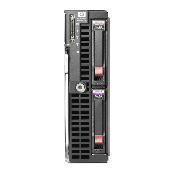
Serial label pull tab Release button Server blade release lever Power On/Standby button Hard drive bay 1 Hard drive bay 2 *The SUV connector and the HP c-Class Blade SUV Cable are for some server blade configuration and diagnostic procedures. Component identification 6... -
Page 7: Front Panel Leds
Front panel LEDs Item Description Status UID LED Blue = Identified Blue flashing = Active remote management Off = No active remote management Health LED Green = Normal Amber flashing = Degraded condition Red flashing = Critical condition Flex-10 NIC 1 LED* Green = Network linked Green flashing = Network activity Off = No link or activity... -
Page 8: Sas And Sata Hard Drive Leds
SAS and SATA hard drive LEDs Item Description Fault/UID LED (amber/blue) Online LED (green) SAS and SATA hard drive LED combinations Online/activity Fault/UID LED Interpretation LED (green) (amber/blue) On, off, or flashing Alternating amber The drive has failed, or a predictive failure alert has been received and blue for this drive;... -
Page 9: System Board Components
Processor socket 1 (populated) TPM connector Cache module connector The symbols correspond to the symbols located on the interconnect bays. For more information, see the HP ProLiant BL460c G6 Server Blade Installation Instructions that ship with the server blade. Component identification 9... -
Page 10: Mezzanine Connector Definitions
Mezzanine connector definitions A PCIe x8 mezzanine connector supports x16 cards at up to x8 speeds. Item PCIe x8, Type I mezzanine card only Mezzanine connector 1 x8, Type 1 or II mezzanine card Mezzanine connector 2 DIMM slot locations DIMM slots are numbered sequentially (1 through 6) for each processor. -
Page 11: Hp C-Class Blade Suv Cable
HP c-Class Blade SUV Cable Item Connector Description Server blade For connecting to the SUV connector on the server blade front panel Video For connecting a video monitor For connecting up to two USB devices Serial For trained personnel to connect a null modem... -
Page 12: Operations
For more information about the Onboard Administrator, see the enclosure setup and installation guide on the HP website (http://www.hp.com/support). For more information about iLO 2, see "Integrated Lights-Out 2 technology (on page 59)." Power down the server blade Before powering down the server blade for any upgrade or maintenance procedures, perform a backup of critical server data and programs. -
Page 13: Remove The Server Blade
Select the Enclosure Information tab, and then select the Overall checkbox in the Device Bays item. Initiate a shutdown from the Virtual Power menu: — Select Momentary Press to initiate a controlled shutdown of applications and the OS. — Select Press and Hold to initiate an emergency shutdown of applications and the OS. IMPORTANT: When the server blade is in standby mode, auxiliary power is still being provided. -
Page 14: Remove The Access Panel
Remove the access panel To remove the component: Power down the server blade (on page 12). Remove the server blade (on page 13). Lift the access panel latch and slide the access panel to the rear. Remove the access panel. WARNING: To reduce the risk of personal injury from hot surfaces, allow the drives and the internal system components to cool before touching them. -
Page 15: Setup
Installing an HP BladeSystem c-Class enclosure Before performing any server blade-specific procedures, install an HP BladeSystem c-Class enclosure. The most current documentation for server blades and other HP BladeSystem components is available at the HP website (http://www.hp.com/go/bladesystem/documentation). Documentation is also available in the following locations: •... -
Page 16: Interconnect Bay Numbering And Device Mapping
3 and 4 Mezzanine 1 5 and 6 Mezzanine 2 7 and 8 For detailed port mapping information, see the HP BladeSystem enclosure installation poster or the HP BladeSystem enclosure setup and installation guide on the HP website (http://www.hp.com/go/bladesystem/documentation). Setup 16... - Page 17 Ports 1 and 3 connect to bay 3 • Ports 2 and 4 connect to bay 4 For detailed port mapping information, see the HP BladeSystem enclosure installation poster or the HP BladeSystem enclosure setup and installation guide on the HP website (http://www.hp.com/go/bladesystem/documentation).
-
Page 18: Connecting To The Network
Connecting to the network To connect the HP BladeSystem to a network, each enclosure must be configured with network interconnect devices to manage signals between the server blades and the external network. Two types of interconnect modules are available for HP BladeSystem c-Class enclosures: Pass-Thru modules and switch modules. - Page 19 Remove the enclosure connector cover. Prepare the server blade for installation. Setup 19...
- Page 20 Install the server blade. Setup 20...
-
Page 21: Hardware Options Installation
Hardware options installation Introduction If more than one option is being installed, read the installation instructions for all the hardware options and identify similar steps to streamline the installation process. WARNING: To reduce the risk of personal injury from hot surfaces, allow the drives and the internal system components to cool before touching them. -
Page 22: Processor Option
Prepare the hard drive. Install the hard drive. Determine the status of the hard drive from the hot-plug SAS hard drive LED combinations ("SAS and SATA hard drive LED combinations" on page 8). Processor option WARNING: To reduce the risk of personal injury from hot surfaces, allow the drives and the internal system components to cool before touching them. - Page 23 IMPORTANT: Processor socket 1 must always be populated. If processor socket 1 is empty, the server blade does not power up. To install the component: Update the system ROM using any standard ROM flash mechanism. Power down the server blade (on page 12). Remove the server blade (on page 13).
- Page 24 Open the processor locking lever and the processor socket retaining bracket. Do not remove the processor socket cover. IMPORTANT: Be sure the processor remains inside the processor installation tool. If the processor has separated from the installation tool, carefully re-insert the processor in the tool. Handle the processor by the edges only, and do not touch the bottom of the processor, especially the contact area.
- Page 25 Align the processor installation tool with the socket, and then install the processor. THE PINS ON THE SYSTEM BOARD ARE VERY FRAGILE AND EASILY DAMAGED. CAUTION: THE PINS ON THE SYSTEM BOARD ARE VERY FRAGILE AND EASILY DAMAGED. To avoid damage to the system board: •...
- Page 26 Press the tabs on the processor installation tool to separate it from the processor, and then remove the tool. Close the processor socket retaining bracket and the processor locking lever. The processor socket cover is automatically ejected. Remove the cover. CAUTION: Be sure to close the processor socket retaining bracket before closing the processor locking lever.
-
Page 27: Memory Options
Remove the thermal interface protective cover from the heatsink. Align and install the heatsink. Alternate tightening the screws until the heatsink is seated properly. Install all DIMM baffles. Install the access panel (on page 14). Memory options IMPORTANT: This server blade does not support mixing RDIMMs and UDIMMs. Attempting to mix these two types causes the server to halt during BIOS initialization. -
Page 28: Memory Subsystem Architecture
• Single- and dual-rank PC3-10600 (DDR-1333) DIMMs operating at 1333 and 1066 MHz • Quad-rank PC3-8500 (DDR-1067) DIMMs operating at 1066 MHz Depending on the processor model, the number of DIMMs installed, and whether UDIMMs or RDIMMs are installed, the memory clock speed may be reduced to 1066 or 800 MHz. For more information on the effect of DIMM slot population, see "General DIMM slot population guidelines (on page 31)."... -
Page 29: Memory Configurations
DIMM type R = RDIMM (registered) E = UDIMM (unbuffered with ECC) For the latest supported memory information, see the QuickSpecs on the HP website (http://www.hp.com). Memory configurations To optimize server blade availability, the server blade supports the following AMP modes: •... -
Page 30: Rdimm Maximum Memory Configurations
For the latest memory configuration information, see the QuickSpecs on the HP website (http://www.hp.com). RDIMM maximum memory configurations The following table lists the maximum memory configuration possible with 8-GB RDIMMs. Rank Single-processor Dual-processor 48 GB 96 GB Single-rank 48 GB... -
Page 31: General Dimm Slot Population Guidelines
General DIMM slot population guidelines Observe the following guidelines for all AMP modes: • Populate DIMM slots for a processor only if the processor is installed. • To maximize performance in multi-processor configurations, distribute the total memory capacity between all processors as evenly as possible. •... -
Page 32: Lockstep Memory Population Guidelines
• Do not install DIMMs in channel 3 for any processor. • DIMMs installed on channel 1 and channel 2 of an installed processor must be identical. • In multi-processor configurations, each processor must have a valid Mirrored Memory configuration. •... -
Page 33: Installing A Dimm
• DIMM configuration on channel 1 and channel 2 of a processor must be identical. • In multi-processor configurations, each processor must have a valid Lockstep Memory configuration. • In multi-processor configurations, each processor may have a different valid Lockstep Memory configuration. -
Page 34: Mezzanine Card Option
Optional mezzanine cards enable network connectivity or provide Fibre Channel support. For mezzanine card locations, see the system board components (on page 9). For mezzanine card mapping, see the HP ProLiant BL460c G6 Server Blade Installation Instructions or see "Interconnect bay numbering and device mapping (on page 16)."... -
Page 35: Cache Module And Battery Pack Option
Remove the mezzanine connector cover. Install the mezzanine card. Press down on the connector to seat the board. Install the access panel (on page 14). Install the server blade ("Installing a server blade" on page 18). Cache module and battery pack option The optional BBWC enabler provides the system with a means for storing and saving data in the event of an unexpected system shutdown. - Page 36 Remove the access panel (on page 14). Remove all hard drives ("Hard drive option" on page 21). Remove the hard drive backplane. Remove the two T-15 screws from the front panel/hard drive cage assembly. Remove the front panel/hard drive cage assembly. Hardware options installation 36...
- Page 37 Connect the BBWC battery pack cable to the cache module. Install the cache module. Route the BBWC battery pack cable ("BBWC battery pack cabling" on page 45). Hardware options installation 37...
- Page 38 Install the battery pack. Install the front panel/hard drive cage assembly. Install the two T-15 screws to secure the front panel/hard drive cage assembly to the chassis. Hardware options installation 38...
-
Page 39: Hp Trusted Platform Module Option
Do not remove an installed TPM. Once installed, the TPM becomes a permanent part of the system board. • When installing or replacing hardware, HP service providers cannot enable the TPM or the encryption technology. For security reasons, only the customer can enable these features. •... -
Page 40: Installing The Trusted Platform Module Board
Recovery Mode after BitLocker™ detects a possible compromise of system integrity. • HP is not liable for blocked data access caused by improper TPM use. For operating instructions, see the encryption technology feature documentation provided by the operating system. - Page 41 Remove the front panel/hard drive cage assembly. CAUTION: Any attempt to remove an installed TPM from the system board breaks or disfigures the TPM security rivet. Upon locating a broken or disfigured rivet on an installed TPM, administrators should consider the system compromised and take appropriate measures to ensure the integrity of the system data.
- Page 42 Install the TPM security rivet by pressing the rivet firmly into the system board. Install the front panel/hard drive cage assembly. Install the two T-15 screws to secure the front panel/hard drive cage assembly to the chassis. Hardware options installation 42...
-
Page 43: Retaining The Recovery Key/Password
Install the hard drive backplane. Press down on the hard drive backplane retainer to seat the board. Install the access panel (on page 14). Install the server blade ("Installing a server blade" on page 18). Power up the server blade (on page 12). Retaining the recovery key/password The recovery key/password is generated during BitLocker™... - Page 44 OS application TPM settings. For more information on firmware updates and hardware procedures, see the HP Trusted Platform Module Best Practices White Paper on the HP website (http://www.hp.com/support).
-
Page 45: Cabling
Mezzanine card cabling: Use the 11.5-inch BBWC battery pack cable. Using the HP c-Class Blade SUV Cable The HP c-Class Blade SUV Cable enables the user to perform server blade administration, configuration, and diagnostic procedures by connecting video and USB devices directly to the server blade. For SUV cable connectors, see "HP c-Class Blade SUV Cable (on page 11)."... -
Page 46: Accessing A Server Blade With Local Kvm
Description Monitor USB mouse USB keyboard HP c-Class Blade SUV Cable Accessing local media devices Use the following configuration when configuring a server blade or loading software updates and patches from a USB CD/DVD-ROM or a USB diskette. Use a USB hub when connecting a USB diskette drive and/or USB CD-ROM drive to the server blade. The USB hub provides additional connections. - Page 47 Connect the HP c-Class Blade SUV cable to the server blade. Connect the video connector to a monitor. Connect a USB hub to one USB connector. Connect the following to the USB hub: USB CD/DVD-ROM drive USB keyboard USB mouse...
-
Page 48: Software And Configuration Utilities
• Rack infrastructure interface service For Microsoft® Windows® OS users, these items are included in the HP ProLiant iLO 2 Standard Blade Edition, available from the HP website (http://www.hp.com/servers/lights-out). Linux OS users can download these components from the HP website (http://www.hp.com/products/servers/linux). -
Page 49: Network-Based Pxe Deployment
The c-Class tab enables you to control specific settings for the HP BladeSystem. iLO 2 also provides web-based status for the HP BladeSystem configuration. For detailed information about iLO 2, refer to the HP Integrated Lights-Out User Guide on the HP website (http://www.hp.com/servers/lights-out). - Page 50 1.3.1_07 1.3.1_08 1.4.1 for Windows® users only 1.4.2 for Linux users only Access the Java™ Runtime Environment versions at the HP website (http://java.sun.com/products/archive/index.html). • DHCP server (IP address assignment) AMD Athlon™ XP processor (700 MHz or greater recommended), AMD Athlon™ 64 processor, or Intel®...
-
Page 51: Deployment Methods
ProLiant server health - whether physical or virtual, deploy ProLiant servers quickly, optimize power consumption, and control ProLiant servers from anywhere. HP Insight Control server deployment is a key component of Insight Control which provides an automated, simple-to-use solution for bare-metal deployment and configuration of HP ProLiant servers with an operating system or virtualization platform. - Page 52 This automated server configuration process cuts time from each deployment, making it possible to scale rapid, high-volume server deployments. For more information, and to download the SmartStart Scripting Toolkit, see the HP website (http://www.hp.com/servers/sstoolkit). CD-ROM deployment CD-ROM deployment involves using a bootable CD that executes scripts to configure the hardware and install the OS.
-
Page 53: Diskette Image Deployment
To deploy with a boot CD: Use the HP c-Class Blade SUV Cable to connect a USB CD-ROM drive to the server blade. Refer to "Connecting locally to a server blade with video and USB devices (on page 45)." Insert the boot CD into the USB CD-ROM drive. -
Page 54: Configuration Tools
• SAN storage drivers are loaded. Refer to supporting white papers and the HP website (http://www.hp.com/servers/rdp). For SAN configuration information for the server blade, refer to the HP StorageWorks SAN Design Reference Guide on the HP website (http://h18000.www1.hp.com/products/storageworks/san/documentation.html). Configuration tools... -
Page 55: Hp Rom-Based Setup Utility
Selecting the primary boot controller • Configuring memory options • Language selection For more information on RBSU, see the HP ROM-Based Setup Utility User Guide on the Documentation CD or the HP website (http://www.hp.com/support/smartstart/documentation). Using RBSU To use RBSU, use the following keys: •... -
Page 56: Boot Options
RBSU by pressing the F9 key when prompted. After the settings are selected, exit RBSU and allow the server to reboot automatically. For more information on RBSU, see the HP ROM-Based Setup Utility User Guide on the Documentation CD or the HP website (http://www.hp.com/support/smartstart/documentation). -
Page 57: Array Configuration Utility
Select Mirrored Memory with Advanced ECC Support. Press the Enter key. Press the Esc key to exit the current menu or press the F10 key to exit RBSU. For more information on mirrored memory, see the white paper on the HP website (http://h18000.www1.hp.com/products/servers/technology/memoryprotection.html). Configuring lockstep memory... -
Page 58: Option Rom Configuration For Arrays
Mozilla Firefox 2.0 or later For Linux servers, see the README.TXT file for additional browser and support information. For more information, see the Configuring Arrays on HP Smart Array Controllers Reference Guide on the Documentation CD or the HP website (http://www.hp.com). -
Page 59: Management Tools
ASR increases server availability by restarting the server within a specified time after a system hang or shutdown. At the same time, the HP SIM console notifies you by sending a message to a designated pager number that ASR has restarted the system. You can disable ASR from the HP SIM console or through RBSU. -
Page 60: Erase Utility
USB support and functionality USB support HP provides both standard USB 2.0 support and legacy USB 2.0 support. Standard support is provided by the OS through the appropriate USB device drivers. Before the OS loads, HP provides support for USB devices through legacy USB support, which is enabled by default in the system ROM. -
Page 61: Diagnostic Tools
Diagnostic tools HP Insight Diagnostics HP Insight Diagnostics is a proactive server blade management tool, available in both offline and online versions, that provides diagnostics and troubleshooting capabilities to assist IT administrators who verify server blade installations, troubleshoot problems, and perform repair validation. -
Page 62: Remote Support And Analysis Tools
HP strongly recommends that you install HP Insight Remote Support software to complete the installation or upgrade of your product and to enable enhanced delivery of your HP Warranty, HP Care Pack Service, or HP contractual support agreement. HP Insight Remote Support supplements your monitoring 24 x 7 to ensure maximum system availability by providing intelligent event diagnosis, and automatic, secure submission of hardware event notifications to HP, which will initiate a fast and accurate resolution, based on your product’s... -
Page 63: Proliant Support Packs
ROM upgrades required by each target server For more information, see the HP Smart Update Manager User Guide. The guide and the HP Smart Update Manager utility are available from the ProLiant Firmware Maintenance CD. This CD and others can be downloaded free of charge from the SmartStart download page on the HP website (http://www.hp.com/go/support). -
Page 64: Care Pack
Care Pack HP Care Pack Services offer upgraded service levels to extend and expand bundled services with easy-to-buy, easy-to-use support packages that help you make the most of your server investments. For more information, see the HP website (http://www.hp.com/services/carepack). Software and configuration utilities 64... -
Page 65: Troubleshooting
The HP BladeSystem c-Class Enclosure Troubleshooting Guide provides procedures and solutions for troubleshooting HP BladeSystem c-Class enclosures. This guide explains how to use the Insight Display to troubleshoot enclosures, and it includes a flowchart to help you navigate the troubleshooting process. To view the guide, see the HP website (http://www.hp.com/support/BladeSystem_Enclosure_TSG_en). -
Page 66: Symbols On Equipment
Warnings WARNING: Only authorized technicians trained by HP should attempt to repair this equipment. All troubleshooting and repair procedures are detailed to allow only subassembly/module-level repair. Because of the complexity of the individual boards and subassemblies, no one should attempt to make repairs at the component level or to make modifications to any printed wiring board. -
Page 67: Symptom Information
If the problem occurs randomly, what is the duration or frequency? To answer these questions, the following information may be useful: • Run HP Insight Diagnostics (on page 61) and use the survey page to view the current configuration or to compare it to previous configurations. •... -
Page 68: Performing Processor Procedures In The Troubleshooting Process
HP recommends you have access to the server documentation for server-specific information. HP recommends you have access to the SmartStart CD for value-added software and drivers required during the troubleshooting process. Download the current version of SmartStart from the HP website (http://www.hp.com/servers/smartstart). -
Page 69: Loose Connections
HP website (http://www.hp.com/support). Troubleshooting flowcharts To effectively troubleshoot a problem, HP recommends that you start with the first flowchart in this section, "Start diagnosis flowchart (on page 70)," and follow the appropriate diagnostic path. If the other flowcharts... -
Page 70: Start Diagnosis Flowchart
do not provide a troubleshooting solution, follow the diagnostic steps in "General diagnosis flowchart (on page 71)." The General diagnosis flowchart is a generic troubleshooting process to be used when the problem is not server-specific or is not easily categorized into the other flowcharts. The available flowcharts include: •... -
Page 71: General Diagnosis Flowchart
General diagnosis flowchart The General diagnosis flowchart provides a generic approach to troubleshooting. If you are unsure of the problem, or if the other flowcharts do not fix the problem, use the following flowchart. Item "Symptom information (on page 67)" "Loose connections (on page 69)"... - Page 72 Guide located on the Documentation CD or see "Troubleshooting resources (on page 65)" "Breaking the server down to the minimum hardware configuration (on page 68)" in the HP ProLiant Servers Troubleshooting Guide located on the Documentation CD or see "Troubleshooting resources (on page 65)" •...
-
Page 73: Server Blade Power-On Problems Flowchart
Server blade power-on problems flowchart Symptoms: • The server does not power on. • The system power LED is off or amber. Troubleshooting 73... - Page 74 Improperly seated component or interlock problem • Faulty internal component Item "Component identification (on page 6)" Maintenance and service guides for c-Class server blades, located on the HP website (http://www.hp.com/go/bladesystem/documentation) Integrated Lights-Out User Guide located on the HP website (http://www.hp.com/servers/lights-out) Troubleshooting 74...
-
Page 75: Post Problems Flowchart
POST problems flowchart Symptoms: • Server does not complete POST NOTE: The server has completed POST when the system attempts to access the boot device. • Server completes POST with errors Possible problems: • Improperly seated or faulty internal component •... - Page 76 "Troubleshooting resources (on page 65)" "Breaking the server down to the minimum hardware configuration (on page 68)" or in the HP ProLiant Servers Troubleshooting Guide located on the Documentation CD or see "Troubleshooting resources (on page 65)" "Symptom information (on page 67)"...
-
Page 77: Os Boot Problems Flowchart
OS boot problems flowchart There are two ways to use SmartStart when diagnosing OS boot problems on a server blade: • Use iLO to remotely attach virtual devices to mount the SmartStart CD onto the server blade. • Use a local I/O cable and drive to connect to the server blade, and then restart the server blade. Symptoms: •... - Page 78 Guide located on the Documentation CD or see "Troubleshooting resources (on page 65)" • Controller documentation "HP Insight Diagnostics (on page 61)" or in the HP ProLiant Servers Troubleshooting Guide located on the Documentation CD or see "Troubleshooting resources (on page 65)" •...
-
Page 79: Server Fault Indications Flowchart
* See the server blade OS boot problems flowchart (on page 77) Server fault indications flowchart Symptoms: • Server boots, but a fault event is reported by Insight Management Agents • Server boots, but the internal health LED, external health LED, or component health LED is red or amber Troubleshooting 79... - Page 80 • System overtemperature condition Item • "Integrated Management Log (on page 61)" or in the HP ProLiant Servers Troubleshooting Guide located on the Documentation CD or see "Troubleshooting resources (on page 65)" • "Event list error messages" in the HP ProLiant Servers Troubleshooting Guide located on the Documentation CD or see "Troubleshooting...
-
Page 81: Post Error Messages And Beep Codes
POST error messages and beep codes For a complete listing of error messages, refer to the "POST error messages" in the HP ProLiant Servers Troubleshooting Guide located on the Documentation CD or on the HP website (http://www.hp.com/support). Troubleshooting 81... - Page 82 WARNING: To avoid potential problems, ALWAYS read the warnings and cautionary information in the server documentation before removing, replacing, reseating, or modifying system components. Troubleshooting 82...
-
Page 83: Battery Replacement
Battery replacement If the server blade no longer automatically displays the correct date and time, you may need to replace the battery that provides power to the real-time clock. Under normal use, battery life is 5 to 10 years. WARNING: The computer contains an internal lithium manganese dioxide, a vanadium pentoxide, or an alkaline battery pack. - Page 84 Remove the battery. IMPORTANT: Replacing the system board battery resets the system ROM to its default configuration. After replacing the battery, reconfigure the system through RBSU. To replace the component, reverse the removal procedure. For more information about battery replacement or proper disposal, contact an authorized reseller or an authorized service provider.
-
Page 85: Regulatory Compliance Notices
Regulatory compliance notices Regulatory compliance identification numbers For the purpose of regulatory compliance certifications and identification, this product has been assigned a unique regulatory model number. The regulatory model number can be found on the product nameplate label, along with all required approval markings and information. When requesting compliance information for this product, always refer to this regulatory model number. -
Page 86: Declaration Of Conformity For Products Marked With The Fcc Logo, United States Only
Hewlett-Packard Company P. O. Box 692000, Mail Stop 530113 Houston, Texas 77269-2000 • 1-800-HP-INVENT (1-800-474-6836). (For continuous quality improvement, calls may be recorded or monitored.) For questions regarding this FCC declaration, contact us by mail or telephone: • Hewlett-Packard Company P. -
Page 87: European Union Regulatory Notice
Compliance with these directives implies conformity to applicable harmonized European standards (European Norms) that are listed in the EU Declaration of Conformity issued by HP for this product or product family and available (in English only) either within the product documentation or at the following HP website (http://www.hp.eu/certificates) (type the product number in the search field). -
Page 88: Japanese Notice
This symbol on the product or on its packaging indicates that this product must not be disposed of with your other household waste. Instead, it is your responsibility to dispose of your waste equipment by handing it over to a designated collection point for the recycling of waste electrical and electronic equipment. -
Page 89: Chinese Notice
Batteries, battery packs, and accumulators should not be disposed of together with the general household waste. To forward them to recycling or proper disposal, use the public collection system or return them to HP, an authorized HP Partner, or their agents. Regulatory compliance notices 89... -
Page 90: Taiwan Battery Recycling Notice
For more information about battery replacement or proper disposal, contact an authorized reseller or an authorized service provider. Taiwan battery recycling notice The Taiwan EPA requires dry battery manufacturing or importing firms in accordance with Article 15 of the Waste Disposal Act to indicate the recovery marks on the batteries used in sales, giveaway or promotion. Contact a qualified Taiwanese recycler for proper battery disposal. -
Page 91: Electrostatic Discharge
Electrostatic discharge Preventing electrostatic discharge To prevent damaging the system, be aware of the precautions you need to follow when setting up the system or handling parts. A discharge of static electricity from a finger or other conductor may damage system boards or other static-sensitive devices. -
Page 92: Specifications
Specifications Environmental specifications Specification Value — Temperature range* 10°C to 35°C (50°F to 95°F) Operating -30°C to 60°C (-22°F to 140°F) Non-operating — Relative humidity (noncondensing)** 10% to 90% @ 28°C (82.4°F) Operating 5% to 95% @ 38.7°C (101.7°F) Non-operating —... -
Page 93: Technical Support
If during the diagnosis period HP (or HP service providers or service partners) identifies that the repair can be accomplished by the use of a CSR part, HP will ship that part directly to you for replacement. There are two categories of CSR parts: •... - Page 94 HP specifies in the materials shipped with a replacement CSR part whether a defective part must be returned to HP. In cases where it is required to return the defective part to HP, you must ship the defective part back to HP within a defined period of time, normally five (5) business days. The defective part must be returned with the associated documentation in the provided shipping material.
- Page 95 HP sono realizzati con numerosi componenti che possono essere riparati direttamente dal cliente (CSR, Customer Self Repair). Se in fase di diagnostica HP (o un centro di servizi o di assistenza HP) identifica il guasto come riparabile mediante un ricambio CSR, HP lo spedirà direttamente al cliente per la sostituzione.
- Page 96 HP podrá cobrarle por el de sustitución. En el caso de todas sustituciones que lleve a cabo el cliente, HP se hará cargo de todos los gastos de envío y devolución de componentes y escogerá la empresa de transporte que se utilice para dicho servicio.
- Page 97 HP. Informatie over Service Partners vindt u op de HP website (http://www.hp.com/go/selfrepair). Reparo feito pelo cliente Os produtos da HP são projetados com muitas peças para reparo feito pelo cliente (CSR) de modo a minimizar o tempo de reparo e permitir maior flexibilidade na substituição de peças com defeito. Se, durante o período de diagnóstico, a HP (ou fornecedores/parceiros de serviço da HP) concluir que o reparo...
- Page 98 Opcional – Peças cujo reparo feito pelo cliente é opcional. Essas peças também são projetadas para o reparo feito pelo cliente. No entanto, se desejar que a HP as substitua, pode haver ou não a cobrança de taxa adicional, dependendo do tipo de serviço de garantia destinado ao produto.
- Page 99 Technical support 99...
- Page 100 Technical support 100...
-
Page 101: Acronyms And Abbreviations
Acronyms and abbreviations ABEND abnormal end Array Configuration Utility Array Diagnostics Utility Advanced Memory Protection Automatic Server Recovery BBWC battery-backed write cache Fibre Channel iLO 2 Integrated Lights-Out 2 Integrated Management Log ORCA Option ROM Configuration for Arrays physical to virtual Performance Management Pack Acronyms and abbreviations 101... - Page 102 POST Power-On Self Test ProLiant Support Pack Preboot Execution Environment RBSU ROM-Based Setup Utility Rapid Deployment Pack RILOE Remote Insight Lights-Out Edition serial attached SCSI SATA serial ATA Systems Insight Manager Server Migration Pack unit identification universal serial bus virtual to physical virtual to virtual Acronyms and abbreviations 102...
- Page 103 Version Control Agent VCRM Version Control Repository Manager Acronyms and abbreviations 103...
-
Page 104: Index
30 BBWC battery pack 35 deployment infrastructure 49 beep codes 81 deployment methods 48, 49, 51 before you contact HP 93 deployment overview 49 BIOS (Basic Input/Output System) 56, 59 device mapping 16 BIOS Serial Console 56 DHCP server 48... - Page 105 LEDs, hard drive 8 heatsink blank 22 LEDs, NIC 7 help resources 93 LEDs, SAS hard drive 8 HP c-Class Blade SUV Cable 6, 11, 45 LEDs, SATA hard drive 8 HP contact information 93 LEDs, troubleshooting 65 HP Insight Diagnostics 61...
- Page 106 processors 9, 22, 68 loose connections 69 Product ID 58 ProLiant Support Pack (PSP) 63 PSP (ProLiant Support Pack) 63 maintenance guidelines 62 PSPs, overview 63 management tools 48, 59 PXE (preboot execution environment) 49, 51 memory 27, 28, 57 PXE deployment 49, 51 memory configurations 29 memory options 21...
- Page 107 70 static electricity 91 support 62, 93 support packs 54 warnings 66 supported operating systems 63 website, HP 93 SUV connector 6, 11, 45 switches, interconnect 15 symbols on equipment 66 symptom information 67 system board 9...