Table of Contents
Advertisement
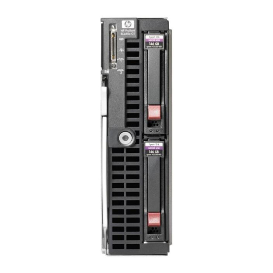
HP ProLiant BL460c G7 Server Blade
Maintenance and Service Guide
Abstract
This guide describes identification and maintenance procedures, diagnostic tools, specifications and requirements for hardware components and
software. This guide is for an experienced service technician. HP assumes you are qualified in the servicing of computer equipment, trained in
recognizing hazards in products, and are familiar with weight and stability precautions.
Part Number: 613019-002
February 2011
Edition: 2
Advertisement
Table of Contents

Related Manuals for HP ProLiant BL460c G7


Summary of Contents for HP ProLiant BL460c G7
-
Page 1: Hp Proliant Bl460C G7 Server Blade
This guide describes identification and maintenance procedures, diagnostic tools, specifications and requirements for hardware components and software. This guide is for an experienced service technician. HP assumes you are qualified in the servicing of computer equipment, trained in recognizing hazards in products, and are familiar with weight and stability precautions. - Page 2 © Copyright 2010, 2011 Hewlett-Packard Development Company, L.P. The information contained herein is subject to change without notice. The only warranties for HP products and services are set forth in the express warranty statements accompanying such products and services. Nothing herein should be construed as constituting an additional warranty. HP shall not be liable for technical or editorial errors or omissions contained herein.
-
Page 3: Table Of Contents
HP Trusted Platform Module ........................56 Diagnostic tools .......................... 57 Troubleshooting resources ........................57 HP Insight Diagnostics ..........................57 HP Insight Diagnostics survey functionality ....................57 Integrated Management Log ........................58 HP Insight Remote Support software ......................58 USB support and functionality ........................59 USB support .......................... - Page 4 Cabling ............................. 60 BBWC battery pack or FBWC capacitor pack cabling ................. 60 Using the HP c-Class Blade SUV Cable ...................... 60 Connecting locally to a server blade with video and USB devices ..............60 Accessing a server blade with local KVM ..................61 Accessing local media devices ......................
-
Page 5: Customer Self Repair
HP specifies in the materials shipped with a replacement CSR part whether a defective part must be returned to HP. In cases where it is required to return the defective part to HP, you must ship the defective part back to HP within a defined period of time, normally five (5) business days. The defective part must be returned with the associated documentation in the provided shipping material. - Page 6 HP sono realizzati con numerosi componenti che possono essere riparati direttamente dal cliente (CSR, Customer Self Repair). Se in fase di diagnostica HP (o un centro di servizi o di assistenza HP) identifica il guasto come riparabile mediante un ricambio CSR, HP lo spedirà direttamente al cliente per la sostituzione.
- Page 7 La mancata restituzione del componente può comportare la fatturazione del ricambio da parte di HP. Nel caso di riparazione da parte del cliente, HP sostiene tutte le spese di spedizione e resa e sceglie il corriere/vettore da utilizzare.
- Page 8 Si, durante la fase de diagnóstico, HP (o los proveedores o socios de servicio de HP) identifica que una reparación puede llevarse a cabo mediante el uso de un componente CSR, HP le enviará dicho componente directamente para que realice su sustitución. Los componentes CSR se clasifican en dos categorías:...
- Page 9 HP podrá cobrarle por el de sustitución. En el caso de todas sustituciones que lleve a cabo el cliente, HP se hará cargo de todos los gastos de envío y devolución de componentes y escogerá la empresa de transporte que se utilice para dicho servicio.
- Page 10 Opcional – Peças cujo reparo feito pelo cliente é opcional. Essas peças também são projetadas para o reparo feito pelo cliente. No entanto, se desejar que a HP as substitua, pode haver ou não a cobrança de taxa adicional, dependendo do tipo de serviço de garantia destinado ao produto.
- Page 11 No caso desse serviço, a substituição de peças CSR é obrigatória. Se desejar que a HP substitua essas peças, serão cobradas as despesas de transporte e mão-de-obra do serviço. Customer self repair 11...
- Page 12 Customer self repair 12...
- Page 13 Customer self repair 13...
- Page 14 Customer self repair 14...
- Page 15 Customer self repair 15...
-
Page 16: Illustrated Parts Catalog
Illustrated parts catalog Server blade components Item Description Spare part Customer self repair number (on page 5) Mechanical components Access panel 619822-001 Mandatory Hard drive blank 392613-001 Mandatory Front panel/hard drive cage assembly 619824-001 Mandatory Hardware and plastics kit 619821-001 Mandatory a) Heatsink blank —... - Page 17 Item Description Spare part Customer self repair number (on page 5) Processors — — a) 2.00-GHz Intel® Xeon® E5503 processor* ** 594889-001 Optional b) 2.13-GHz Intel® Xeon® E5506 processor* ** 536892-001 Optional c) 2.40-GHz Intel® Xeon® E5620 processor* ** 594887-001 Optional d) 2.53-GHz Intel®...
- Page 18 HP NC532m Dual Port 10GbE BL-c Adapter 466308-001 Mandatory f) HP NC542m Dual Port Flex-10 10GbE Multifunction 539933-001 Mandatory BL-c Adapter g) HP NC550m PCIe x8 Dual Port 10 GbE Flex-10 586445-001 Mandatory Ethernet Adapter h) HP BLc QLogic iSCSI Dual Port Adapter 488081-001 Mandatory...
- Page 19 Optional—Parts for which customer self repair is optional. These parts are also designed for customer self repair. If, however, you require that HP replace them for you, there may or may not be additional charges, depending on the type of warranty service designated for your product.
- Page 20 Optional: Opcional—Peças cujo reparo feito pelo cliente é opcional. Essas peças também são projetadas para o reparo feito pelo cliente. No entanto, se desejar que a HP as substitua, pode haver ou não a cobrança de taxa adicional, dependendo do tipo de serviço de garantia destinado ao produto.
- Page 21 Illustrated parts catalog 21...
-
Page 22: Removal And Replacement Procedures
Required tools You need the following items for some procedures: • T-15 Torx screwdriver (provided inside the access panel) • HP Insight Diagnostics software ("HP Insight Diagnostics" on page 57) Safety considerations Before performing service procedures, review all the safety information. -
Page 23: Symbols On Equipment
Symbols on equipment The following symbols may be placed on equipment to indicate the presence of potentially hazardous conditions. This symbol indicates the presence of hazardous energy circuits or electric shock hazards. Refer all servicing to qualified personnel. WARNING: To reduce the risk of injury from electric shock hazards, do not open this enclosure. -
Page 24: Remove The Server Blade
• Press and release the Power On/Standby button. This method initiates a controlled shutdown of applications and the OS before the server blade enters standby mode. • Press and hold the Power On/Standby button for more than 4 seconds to force the server blade to enter standby mode. -
Page 25: Access Panel
Remove the server blade. Place the server blade on a flat, level work surface. WARNING: To reduce the risk of personal injury from hot surfaces, allow the drives and the internal system components to cool before touching them. CAUTION: To prevent damage to electrical components, properly ground the server blade before beginning any installation procedure. -
Page 26: Hard Drive Blank
Hard drive blank Remove the hard drive blank. To replace the component, reverse the removal procedure. Hard drive IMPORTANT: Hot-plug capability and drive LED support are only available when a supported optional controller is installed in the server. To remove the component: Back up all data on the hard drive. -
Page 27: Battery Tray
Remove the hard drive. To replace the component, reverse the removal procedure. When adding hard drives to the server blade, observe the following general guidelines: • The system automatically sets all drive numbers. • If only one hard drive is used, install it in the bay with the lowest drive number. •... -
Page 28: Mezzanine Connector Cover
Remove the battery tray. To replace the component, reverse the removal procedure. Mezzanine connector cover To remove the component: Power down the server blade (on page 23). Remove the server blade (on page 24). Remove the access panel ("Access panel" on page 25). Remove the mezzanine connector cover. -
Page 29: Dimm Baffles
DIMM baffles To remove the component: Power down the server blade (on page 23). Remove the server blade (on page 24). Remove the access panel ("Access panel" on page 25). Remove the DIMM baffle. To replace the component, reverse the removal procedure. DIMMs IMPORTANT: This server blade does not support mixing RDIMMs and UDIMMs. -
Page 30: Heatsink Blank
Remove the DIMM. To replace the component, reverse the removal procedure. Heatsink blank To remove the component: Power down the server blade (on page 23). Remove the server blade (on page 24). Remove the access panel ("Access panel" on page 25). Remove the heatsink blank. -
Page 31: Mezzanine Card
Mezzanine card Optional mezzanine cards enable network connectivity or provide Fibre Channel support. For mezzanine card locations, see the system board components (on page 66). Because mezzanine cards are supported on multiple server blade models, the mezzanine card may have captive screws that are not required to secure it to the server blade. -
Page 32: Hard Drive Backplane
Install the mezzanine card. Press down on the connector to seat the board. Install the access panel ("Access panel" on page 25). Hard drive backplane To remove the component: Power down the server blade (on page 23). Remove the server blade (on page 24). Remove the access panel ("Access panel"... -
Page 33: Front Panel/Hard Drive Cage Assembly
Remove the hard drive backplane. To replace the component: Install the hard drive backplane. Press down on the hard drive backplane retainer to seat the board. Install the hard drives ("Hard drive" on page 26). Install the hard drive blanks ("Hard drive blank"... -
Page 34: Battery-Backed Write Cache And Flash-Backed Write Cache Procedures
Remove the access panel ("Access panel" on page 25). Remove all hard drives ("Hard drive" on page 26). Remove all hard drive blanks ("Hard drive blank" on page 26). Remove the hard drive backplane ("Hard drive backplane" on page 32). Remove the two T-15 screws from the front panel/hard drive cage assembly. -
Page 35: Removing The Battery Pack Or Capacitor Pack
Remove all hard drives ("Hard drive" on page 26). Remove all hard drive blanks ("Hard drive blank" on page 26). Remove the hard drive backplane ("Hard drive backplane" on page 32). Remove the front panel/hard drive cage assembly ("Front panel/hard drive cage assembly"... -
Page 36: Recovering The Data From The Cache
Disconnect the BBWC or FBWC cable from the cache module. Remove the battery pack or capacitor pack. To replace the component, reverse the removal procedure. Recovering the data from the cache Use one of the following procedures: • Recovering data from the battery-backed write cache (on page 36) •... - Page 37 Set up a recovery server blade station using an identical server blade model. Do not install any internal drives or BBWC in this server blade. (HP recommends this option.) Find a server blade that has enough empty drive bays to accommodate all the drives from the failed server blade and that meets all the other requirements for drive and array migration.
-
Page 38: Heatsink
If the server blade has failed, remove the controller, cache module ("Removing the cache module" on page 34), and capacitor pack ("Removing the battery pack or capacitor pack" on page 35) from the failed server blade, and install the controller, cache module, and capacitor pack in the recovery server blade. - Page 39 Remove the thermal interface protective cover from the heatsink. CAUTION: To avoid damage to the system board, processor socket, and screws, do not overtighten the heatsink screws. Use the wrench supplied with the system to reduce the possibility of overtightening the screws. Align and install the heatsink.
-
Page 40: Processor
To remove the component: Update the system ROM. Locate and download the latest ROM version from the HP website (http://www.hp.com/support). Follow the instructions on the website to update the system ROM. Power down the server blade (on page 23). - Page 41 Line up the processor tool, ensuring the locking lever graphic on the tool is oriented correctly. Press in on the plastic tabs, and then place the tool on the processor. Release the tabs, and then carefully lift the processor and tool straight up. Carefully rotate the tool, and then push in and release the tabs to secure the processor in the tool.
- Page 42 Carefully insert the processor into the processor installation tool. Handle the processor by the edges only, and do not touch the bottom of the processor, especially the contact area. Removal and replacement procedures 42...
- Page 43 Be sure the tool is oriented correctly. Align the processor installation tool with the socket, and then install the processor. THE PINS ON THE SYSTEM BOARD ARE VERY FRAGILE AND EASILY DAMAGED. CAUTION: THE PINS ON THE SYSTEM BOARD ARE VERY FRAGILE AND EASILY DAMAGED. To avoid damage to the system board: •...
- Page 44 Press and hold the tabs on the processor installation tool to separate it from the processor, and then remove the tool. Close the processor socket retaining bracket and the processor locking lever. CAUTION: Be sure to close the processor socket retaining bracket before closing the processor locking lever.
-
Page 45: System Board
Align and install the heatsink. Alternate tightening the screws until the heatsink is seated properly. Install the front panel/hard drive cage assembly ("Front panel/hard drive cage assembly" on page 33). Install the hard drive backplane ("Hard drive backplane" on page 32). Install the hard drives ("Hard drive"... - Page 46 Open the processor locking lever and the processor socket retaining bracket. Using the processor tool, remove the processor from the system board: Line up the processor tool, ensuring the locking lever graphic on the tool is oriented correctly. Press in on the plastic tabs, and then place the tool on the processor. Release the tabs, and then carefully lift the processor and tool straight up.
- Page 47 Carefully rotate the tool, and then push in and release the tabs to secure the processor in the tool. CAUTION: To avoid damage to the processor, do not touch the bottom of the processor, especially the contact area. Remove the system board assembly. Removal and replacement procedures 47...
- Page 48 To replace the system board: Install the spare system board. CAUTION: Failure to completely open the processor locking lever prevents the processor from seating during installation, leading to hardware damage. Open the processor locking lever and the processor socket retaining bracket. Do not remove the processor socket cover.
- Page 49 If the processor has separated from the installation tool, carefully re-insert the processor in the tool. Handle the processor by the edges only, and do not touch the bottom of the processor, especially the contact area. Removal and replacement procedures 49...
- Page 50 Align the processor installation tool with the socket, and then install the processor. THE PINS ON THE SYSTEM BOARD ARE VERY FRAGILE AND EASILY DAMAGED. CAUTION: THE PINS ON THE SYSTEM BOARD ARE VERY FRAGILE AND EASILY DAMAGED. To avoid damage to the system board: •...
- Page 51 Press the tabs on the processor installation tool to separate it from the processor, and then remove the tool. Close the processor socket retaining bracket and the processor locking lever. The processor socket cover is automatically ejected. Remove the cover. CAUTION: Be sure to close the processor socket retaining bracket before closing the processor locking lever.
- Page 52 Apply all the grease to the top of the processor in the following pattern to ensure even distribution. Install the heatsink ("Heatsink" on page 38). IMPORTANT: Install all components with the same configuration that was used on the failed system board. Install all components removed from the failed system board.
-
Page 53: System Battery
Press the Esc key to close the menu. Press the Esc key to exit RBSU. Press the F10 key to confirm exiting RBSU. The server blade automatically reboots. System battery If the server blade no longer automatically displays the correct date and time, you may need to replace the battery that provides power to the real-time clock. -
Page 54: Server Blade Release Lever
Identify the battery location ("System board components" on page 66). Remove the battery. IMPORTANT: Replacing the system board battery resets the system ROM to its default configuration. After replacing the battery, reconfigure the system through RBSU. To replace the component, reverse the removal procedure. Server blade release lever To remove the component: Power down the server blade (on page 23). -
Page 55: Release Button
Remove the server blade release lever. To replace the component, reverse the removal procedure. Release button To remove the component: Power down the server blade (on page 23). Remove the server blade (on page 24). Remove the access panel ("Access panel"... -
Page 56: Hp Trusted Platform Module
If you suspect a TPM board failure, leave the TPM installed and remove the system board ("System board" on page 45). Contact an HP authorized service provider for a replacement system board and TPM board. Removal and replacement procedures 56... -
Page 57: Diagnostic Tools
HP website (http://www.hp.com/support/BladeSystem_Enclosure_TSG_en). HP Insight Diagnostics HP Insight Diagnostics is a proactive server blade management tool, available in both offline and online versions, that provides diagnostics and troubleshooting capabilities to assist IT administrators who verify server blade installations, troubleshoot problems, and perform repair validation. -
Page 58: Integrated Management Log
HP strongly recommends that you install HP Insight Remote Support software to complete the installation or upgrade of your product and to enable enhanced delivery of your HP Warranty, HP Care Pack Service, or HP contractual support agreement. HP Insight Remote Support supplements your monitoring 24 x 7 to ensure maximum system availability by providing intelligent event diagnosis, and automatic, secure submission of hardware event notifications to HP, which will initiate a fast and accurate resolution, based on your product’s... -
Page 59: Usb Support And Functionality
USB support and functionality USB support HP provides both standard USB 2.0 support and legacy USB 2.0 support. Standard support is provided by the OS through the appropriate USB device drivers. Before the OS loads, HP provides support for USB devices through legacy USB support, which is enabled by default in the system ROM. -
Page 60: Cabling
Mezzanine card cabling: Use the 29.21-cm (11.50-in) cable. Using the HP c-Class Blade SUV Cable The HP c-Class Blade SUV Cable enables the user to perform server blade administration, configuration, and diagnostic procedures by connecting video and USB devices directly to the server blade. For SUV cable connectors, see "HP c-Class Blade SUV Cable (on page 69)."... -
Page 61: Accessing A Server Blade With Local Kvm
Description Monitor USB mouse USB keyboard HP c-Class Blade SUV Cable Accessing local media devices Use the following configuration when configuring a server blade or loading software updates and patches from a USB CD/DVD-ROM or a USB diskette. Use a USB hub when connecting a USB diskette drive and/or USB CD-ROM drive to the server blade. The USB hub provides additional connections. - Page 62 Connect the HP c-Class Blade SUV cable to the server blade. Connect the video connector to a monitor. Connect a USB hub to one USB connector. Connect the following to the USB hub: USB CD/DVD-ROM drive USB keyboard USB mouse...
-
Page 63: Component Identification
Serial label pull tab Release button Server blade release lever Power On/Standby button Hard drive bay 1 Hard drive bay 2 *The SUV connector and the HP c-Class Blade SUV Cable are for some server blade configuration and diagnostic procedures. Component identification 63... -
Page 64: Front Panel Leds
Front panel LEDs Item Description Status UID LED Blue = Identified Blue flashing = Active remote management Off = No active remote management Health LED Green = Normal Amber flashing = Degraded condition Red flashing = Critical condition Flex 1 LED* Green = Network linked Green flashing = Network activity Off = No link or activity... -
Page 65: Sas And Sata Hard Drive Leds
SAS and SATA hard drive LEDs Item Description Fault/UID LED (amber/blue) Online LED (green) SAS and SATA hard drive LED combinations Online/activity Fault/UID LED Interpretation LED (green) (amber/blue) On, off, or flashing Alternating amber The drive has failed, or a predictive failure alert has been received and blue for this drive;... -
Page 66: System Board Components
Processor socket 1 (populated) TPM connector Cache module connector The symbols correspond to the symbols located on the interconnect bays. For more information, see the HP ProLiant BL460c G7 Server Blade Installation Instructions that ship with the server blade. Component identification 66... -
Page 67: Mezzanine Connector Definitions
Mezzanine connector definitions Item PCIe x4, Type I mezzanine card only Mezzanine connector 1 x8, Type I or II mezzanine card Mezzanine connector 2 A PCIe x4 mezzanine connector supports x8 cards at up to x4 speeds. A PCIe x8 mezzanine connector supports x16 cards at up to x8 speeds. -
Page 68: System Maintenance Switch
10600 = 1333-MHz 8500 = 1066-MHz DIMM type R = RDIMM (registered) E = UDIMM (unbuffered with ECC) For the latest supported memory information, see the QuickSpecs on the HP website (http://www.hp.com). System maintenance switch Position Function Default iLO 2 security override... -
Page 69: Hp C-Class Blade Suv Cable
HP c-Class Blade SUV Cable Item Connector Description Server blade For connecting to the SUV connector on the server blade front panel Video For connecting a video monitor For connecting up to two USB devices Serial For trained personnel to connect a null modem... -
Page 70: Specifications
Specifications Environmental specifications Specification Value — Temperature range* 10°C to 35°C (50°F to 95°F) Operating -30°C to 60°C (-22°F to 140°F) Non-operating — Relative humidity (noncondensing)** 10% to 90% @ 28°C (82.4°F) Operating 5% to 95% @ 38.7°C (101.7°F) Non-operating —... -
Page 71: Acronyms And Abbreviations
FBWC flash-backed write cache Fibre Channel host bus adapter Host Channel Adapter HP SIM HP Systems Insight Manager iLO 3 Integrated Lights-Out 3 Integrated Management Log PCIe peripheral component interconnect express ProLiant Support Pack Acronyms and abbreviations 71... - Page 72 RBSU ROM-Based Setup Utility serial attached SCSI SATA serial ATA small form-factor Systems Insight Manager serial, USB, video trusted platform module unit identification universal serial bus Acronyms and abbreviations 72...
-
Page 73: Index
CSR (customer self repair) 5 heatsink blank 16, 30, 38 customer self repair (CSR) 5, 16 HP c-Class Blade SUV Cable 60, 63, 69 HP Insight Diagnostics 22, 57 HP Insight Diagnostics survey functionality 57 HP Insight Remote Support software 58... - Page 74 safety information 22 SAS drives 16, 65 LED, health 64, 65 SAS hard drive LEDs 65 LED, power button 64 SAS/SATA LED combinations 65 LED, system power 64 SATA hard drive 16, 65 LEDs 63, 65 SATA hard drive LEDs 65 LEDs, front panel 65 SD card module 16 LEDs, hard drive 65...