Table of Contents
Advertisement
Advertisement
Table of Contents

Related Manuals for Husqvarna MS 360 G


Summary of Contents for Husqvarna MS 360 G
- Page 1 Workshop manual MS 360 G HUSQVARNA CONSTRUCTION PRODUCTS...
- Page 2 LEGEND...
-
Page 3: Table Of Contents
ESD general notice ��������������������������������������������������������������������������������������������������������������������������������������� 5 6. Tools and Special Tools Tools ��������������������������������������������������������������������������������������������������������������������������������������������������������������� 6 7. Components - Navigation MS 360 G Navigation ���������������������������������������������������������������������������������������������������������������������������������� 7 8. Troubleshooting Problem with tile cracks ������������������������������������������������������������������������������������������������������������������������������� 8 9. Repair Instructions Replacing Belt and pulleys ��������������������������������������������������������������������������������������������������������������������������� 9 Replace blade shaft bearings ����������������������������������������������������������������������������������������������������������������������12... -
Page 4: Literature
LITERATURE 3. LITERATURE Workshop Manual The workshop manual covers all workshop maintenance for the MS 360 G� Some very simple and obvious repair work has been omitted� The manual is divided into numbered chapters as well as chapter headings that are specified in bold at the top of each page�... -
Page 5: Safety Instructions
General • No one may repair the MS 360 G unless they have read and understood the contents of this workshop manual� • This workshop manual is written for personnel with general knowledge about the repair and service of MS 360 G�... -
Page 6: Tools And Special Tools
TOOLS AND SPECIAL TOOLS 6. TOOLS AND SPECIAL TOOLS In the list below you will find the tools and the special tools used in this workshop manual. Tools Tool Tool no. Description Wrench set 10-19mm Allen Key, Kit 2�5 - 10 mm 525 45 52-01 Screwdriver Steel Ruler, 0 - 500 mm... -
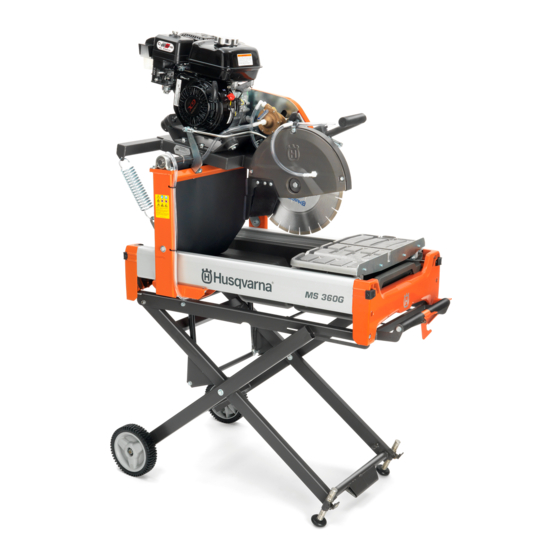
Page 7: Components - Navigation
COMPONENTS - NAVIGATION 7. COMPONENTS - NAVIGATION MS 360 G Navigation 1� Locking knob, depth adjustment 13� Blade Guard 2� Knob, depth stop adjustment 14� Frame 3� Locking nut, depth stop adjustment 15� Splash guard 4� Handle, cutting arm 16� Splash guard 5�... -
Page 8: Troubleshooting
TROUBLESHOOTING 8. TROUBLESHOOTING Problem with tile cracks If the tiles cracks at the end of a cut the blade is most likely not properly aligned with the conveyor cart� See: Check the blade alignment� (p�... -
Page 9: Repair Instructions
REPAIR INSTRUCTIONS 9. REPAIR INSTRUCTIONS Replace Belt and pulleys 1� Remove the belt cover by unscrewing the 2 screws� 2� Release the 2 knobs that hold the water pump and slide it away from the belt and tighten one of the knobs�... - Page 10 REPAIR INSTRUCTIONS 11� Ensure that the key is in place in the slot and then slide the pulley on to the blade shaft� 12� Assemble the center screw with threadlocker (e�g� Loctite 243)� Use a 7/32 inch or 5,5mm pin to lock the rotation of the pulley and tighten the screw to with 35Nm�...
- Page 11 REPAIR INSTRUCTIONS 17� Let the 4 screws holding the engine bracket be a little bit loose when tensioning the belt to keep the engine in a straight position� 18� Tighten the belt to 40Hz ±3� If you do not have a hertz meter, use your thumb and index finger to press the belt together with normal pressure�...
-
Page 12: Replace Blade Shaft Bearings
REPAIR INSTRUCTIONS Replace blade shaft bearings First see Replacing Belt and pulleys (p. 9) 1� Remove the 3 screws to open the blade guard� 2� Lock the rotation of the blade shaft by using a 7/32 inch or 5,5mm pin in the belt pulley stop hole�... - Page 13 REPAIR INSTRUCTIONS 10� Use a workshop press to remove the bearings from the housing� Use a collar that supports the housing but is large enough to let the bearing and the shaft pass� NOTE! Always replace the bearings when the bearing housing have been disassembled since they will get damaged by the disassemble process�...
- Page 14 REPAIR INSTRUCTIONS NOTE! When assembling the new bearings, always press against the inner collar of the bearing to not damage it� The inner collar of the bearing has a higher press fit towards the shaft then the outer collar of the bearing has to the bearing housing�...
-
Page 15: Renovate The Water Pump
REPAIR INSTRUCTIONS Renovate the water pump First see Replacing Belt and pulleys (p. 9) NOTE! Always replace all parts in the renovation kit when disassembling the water pump. Sealing, gasket, washers, impeller and the bearings with the shaft. 1� Loosen the set screw and remove the water pump pulley�... - Page 16 REPAIR INSTRUCTIONS 8� Remove the seal in the impeller by using a screwdriver or a knife� 9� Loosen the set screw and remove the water pump belt pulley� It might be necessary to use a puller� 10� Loosen the sscrew on the water pump housing and separate the water pump housing from the bearing housing�...
-
Page 17: Assembling The Water Pump
REPAIR INSTRUCTIONS Assembling the water pump First see Renovate the water pump (p. 15) NOTE! Always replace all parts in the renovation kit when disassembling the water pump. Sealing, gasket, washers, impeller and the bearings with the shaft. 1� Use a workshop press to fit the new spring loaded sealing in the water pump housing�... - Page 18 REPAIR INSTRUCTIONS 8� Mount the belt pulley to the shaft and tighten the set screw� 9� Use a screwdriver to lock the impeller through the water outlet and tighten it by hand force with help from the belt pulley� NOTE! Check that the impeller rotates freely without friction and noise�...
-
Page 19: Adjust The Blade Depth
REPAIR INSTRUCTIONS Adjust the blade depth 1� Loosen the locking lever for depth adjustment and lower the blade to its lowest position� 2� Loosen the lock nut on the depth adjustment knob� 3� Adjust the depth adjustment knob until the blade is as deep as possible without touching the cart 4�... -
Page 20: Aligning The Blade
REPAIR INSTRUCTIONS Aligning the blade First see Check the blade alignment. (p. 19) 1� Set the saw blade in a low position to get a good weight balance of the saw head during the adjustment� 2� Loosen the 4 screws underneath the frame that holds the saw head�... -
Page 21: Measure/Adjust The Conveyor Cart Wheel Traction
REPAIR INSTRUCTIONS Measure/Adjust the Conveyor Cart Wheel Traction 1� Remove the conveyor cart from the frame� 2� Ensure that the conveyor cart wheels are perpendicular to the conveyor cart anvil as in the illustration to the left� If NOT, take one of the following actions: •... - Page 22 www.husqvarnacp.com 115 86 51-29 English...