Husqvarna WS 482 HF Workshop Manual
Hide thumbs
Also See for WS 482 HF:
- Operator's manual (100 pages) ,
- Operator's manual (68 pages) ,
- Operator's manual (81 pages)
Table of Contents
Advertisement
Quick Links
Advertisement
Table of Contents

Related Manuals for Husqvarna WS 482 HF


Summary of Contents for Husqvarna WS 482 HF
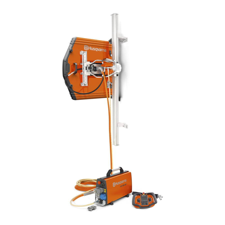
- Page 1 Workshop manual WS 482 HF HUSQVARNA CONSTRUCTION PRODUCTS...
-
Page 2: Table Of Contents
CONTENTS Page LITERATURE HUSQVARNA 2. COMPONENTS – NAVIGATION WS 482 HF FUNCTION TEST 4. BLADE FLANGE HUB 5. ELECTRICAL COMPONENTS – dismantling – assembly 6. FEEDING MOTORS – dismantling – gear housing – bottom bearing, adjustment – assembly – HALL-sensor 7. - Page 3 LITERATURE Workshop manual The workshop manual covers virtually all work in the workshop that involves the WS 482 HF. Some very simple and rather obvious repair work has been omitted. PP 480 HF Driving the wall saw requires a high frequency unit, PP 480 HF.
-
Page 4: Components - Navigation
Manual de instrucciones Lea detenidamente el manual de instrucciones y asegúrese WS 440 HF WS 482 HF de entender su contenido antes de utilizar la máquina. Bedienungsanweisung Lesen Sie die Bedienungsanweisung sorgfältig durch und machen Sie sich mit dem Inhalt vertraut, bevor Sie das Gerät benutzen. -
Page 5: Function Test
FUNCTION TEST Function test In order to determine the status of the current item, it is appropriate to begin by measuring the traction and tooth flank play in the arm feed's worm gear. The tests reveal the condition of the feeding motors, slip clutches and gears, and from this you can determine what action to take. - Page 6 FUNCTION TEST Wear control Check the worm gear play using a dial gauge arranged as shown in the figure. Control measurement should be made level with the Max 1,5 mm centre of the blade flange hub. .06 in. If the play exceeds 1.5 mm (.06 in.) when the arm is pushed with a light press, the worm wheel needs replacing.
- Page 7 BLADE FLANGE HUB Function The obvious task of the blade flange nub is to lock the blade between the flange washers with the centre screw on the outer flange washer. The blade flange hub also has a channel system that supplies the blade with water on both sides.
- Page 8 BLADE FLANGE HUB Bearing – dismantling The easiest way of removing the bearing is by using a hydraulic press. Bearing – assembly When fitting, it is important that a press force is applied to the outer bearing ring to prevent damage to the bearing. Note that the bearing must be pressed slightly below the flat surface to reach the stop under the bearing.
-
Page 9: Electrical Components
ELECTRICAL COMPONENTS Dismantling the socket unit To access more of the saw components the cover must be removed. To remove this, first remove the socket piece on the top of the cover. For work that does not directly affect the socket units, the most appro - priate method is to remove the complete socket unit, as described on this page. - Page 10 ELECTRICAL COMPONENTS Dismantling of the socket components This chapter deals with the removal of electrical components from the machine, which are grouped around the electric socket on the saw head. Releasing the power cables from the enclosure where all the electrical connections converge is necessary for virtually all work on the saw head and saw motor.
- Page 11 ELECTRICAL COMPONENTS 9. The earth wire is secured with a screw in the socket frame. Remove the earth wire. 10. Lift off the socket frame. 11. Lift off the socket enclosure. 12. Lift off the cover. 13. Remove the three outer screws. 14.
- Page 12 Tool for the socket pins A special tool is needed for removing the pins. This can be purchased from Husqvarna: Part no. 523 93 44-01. (Make: Harting: 09 99 000 0319.) 523 93 44-01 Remove the socket pins 22.
-
Page 13: Assembly
ELECTRICAL COMPONENTS Reassembly BLACK Wiring diagram Circuit board Check that cables and sockets are correctly connected using the adjacent simplified BLUE wiring diagram. WHITE For HAL sensor – arm motor BROWN Avoid crushing damage to cables For HAL sensor – carriage motor BLUE Exercise care when assembling the cables to ensure they do not jam causing damage to... - Page 14 ELECTRICAL COMPONENTS 7. Remove the grey rubber seal from the enclosure and push the sockets through the enclosure and then through the seal. 8. Fit the bushing and press down the sockets in this. Clean the socket pins of any oxides and lubricate with Electrolube.
-
Page 15: Dismantling
FEEDING MOTORS Feeding motors The machine has two feeding motors, one for carriage feed (A) and one for the move- ment of the pivoting arm (B). The feeding motor's speed is changed in the gear housing and the screw worm pro - duces a slow motion, which in turn drives the worm wheel of the saw head. -
Page 16: Feeding Motors
FEEDING MOTORS Motors: arm and carriage feed Both motors have the same basic structure. Note, however, the difference between the feeding motors' gear wheels. Left motor – arm feed. Right motor – carriage feed. Replacing the feeding motor The feeding motors are identical for the carriage and arm feed. -
Page 17: Gear Housing
FEEDING MOTORS Gear housing Dismantling 1. Use a pin punch and tap lightly on one corner so that the gear housing releases from the saw head. Under no circumstances must the gear housing be deformed as this leads to poor sealing. The following stages are made easier if the saw is mounted on the track. - Page 18 FEEDING MOTORS Screw worm – dismantling 5. Start by removing the centre screw. Under this there is a flat washer and three washer springs. 6. Knock out the screw worm with a small plastic hammer. 7. Lift out the screw worm. Note the axial bearing for the screw worm.
-
Page 19: Bottom Bearing, Adjustment
FEEDING MOTORS Bottom bearing Remove The feeding motors' screw worms on the opposite side are journalled with axial and radial needle bearings. 1. Remove the four screws to the bearing holder. 2. Lift out the bearing holder. If no actions have been taken that change the length of the gear assembly, the shim on the bottom bearing does not need to be measured or corrected. - Page 20 FEEDING MOTORS Adjustment – axial application Starting position The motor housing must be mounted on the opposite side. The measurement must be made with a fitted stud and axial needle bearing with associated bearing washer. Measuring device The following measurements are made easier using digital depth callipers.
-
Page 21: Assembly
FEEDING MOTORS Assembly 1. Lubricate the screw worms. 2. Lubricate the worm wheel in the saw head. By sliding the machine on the track, the worm wheel for the carriage feed rotates and can be lubricated all around. In the same way, the arm shaft can be turned to facilitate lubrication of its worm wheel. -
Page 22: Hall-Sensor
FEEDING MOTORS HALL sensor The position of the HALL sensor controls the speed of the two feeding motors. By turning the HALL sensor, the motors can be adjusted to the same speed in both directions of rotation, which is the aim of the adjust- ment. - Page 23 FEEDING MOTORS SELECT FUSE Before you can calibrate, two settings must be made: 1. SELECT FUSE Press the arrow buttons to set the value of the mains fuse that the high frequency unit is connected to. Finish by pressing OK. For calibration of the feeding motors, you can select any fuse value.
- Page 24 FEEDING MOTORS CLIBRATE TRAVEL FEEDING 4. Select the menu for travel feed by using one of the arrow keys to go to CALIBRATE TRAVEL FEEDING. 5. Adjust the HALL sensor Turn the wheel on the travel feed fully to its end position, and note the values of the left and right end positions.
-
Page 25: Pivoting Arm
Tool A special tool has been designed to carry out work on the pivoting arm. The tool can be purchased from Husqvarna. Art. no. 575 46 60-01. 575 46 60-01 Dismantling Hose connection 1. You must first disconnect the hose connection between the motor and pivoting arm. - Page 26 PIVOTING ARM Swivel 1. Raise the swivel using a screwdriver. 2. Note the X-rings on the top and bottom of the swivel. Dismantling – blade bracket 1. Remove the six screws. 2. Use a knife to lift the flange washer. 3.
- Page 27 PIVOTING ARM 11. Remove the hub by tightening the screw in the middle. 12. Removed hub. Remove the hub 13. Heat the pressed on ring. 14. Fit the tool 575 46 60-01. 15. Press out the hub. 16. Dismantled hub and gear wheel. Bearing replacement 17.
-
Page 28: Blade Shaft, Saw Hub
PIVOTING ARM Assembly – blade bracket Bearing holder 1. Fit a new O-ring on the bearing holder. 2. Turn the bearing holder and rotate it so that the screw holes align. 3. Turn the pivoting arm. 4. Fit the screws with threadlocker Loctite 243. - Page 29 PIVOTING ARM Shield 7. Fit a new O-ring on the shield. 8. Lubricate the pivoting arm where the O- rings on the shield are in contact with this. Fit the seal holder The seal holders in the following stages must be fitted with a press.
-
Page 30: Transmission
PIVOTING ARM Transmission – supply side The pivoting arm's supply side is connected at the saw head. A shaft from the saw motor passes through the saw head directly to the pivoting arm. The mechanism in the pivoting arm handles power transmission to the saw blade. - Page 31 PIVOTING ARM Remove the drive shaft 10. Remove the drive shaft using a standard puller as shown in the adjoining method. Fasten the puller claw during assembly. 11. Lift up the drive shaft. Remove the gear shafts 12. Remove the ball bearings on the two gear shafts.
- Page 32 PIVOTING ARM Idler bearings Warning The large retaining ring represents an element of risk. Lock the ring with a clamp and wear safety glasses! 6. Pry out the retaining ring at one end 7. Lift the retaining ring with a small screw- driver.
- Page 33 PIVOTING ARM Fit the idler Turn the parts correctly 1. Note how the components must be turned when these are to be mounted in the pivoting arm. 2. Insert the components into the pivoting arm. 3. Turn the arm and the centre bearing and spacer ring.
- Page 34 PIVOTING ARM Bearings Dismantling Remove all bearings using a counter stay device. Support the counterhold with a few pieces of wood. Alternatively you can use a slide hammer. 1. Remove the bearing from the pivoting arm. 2. Remove the bearing in the pivoting arm cover.
-
Page 35: Slip Clutch
PIVOTING ARM Slip clutch Hook nut Function The pivoting arm has two clutch shafts Tab washer with slip clutches that engage if the saw Rotational lock blade is overloaded. It is important for the functioning of the saw that the slip torque is Washer spring correctly adjusted. - Page 36 PIVOTING ARM 3. Lock the hook nut with a tab washer and fold down the tongue. 4. Tighten the hook nut with socket 523 05 77-01 to a torque of around 45 Nm (33 lbf·ft). Turn the clutch shaft 5. Turn the clutch shaft and loosely tighten in the fixture.
-
Page 37: Assembly
PIVOTING ARM Fit the components Put the gear wheels in position The mounting is described below step by step. Pay attention to the gear wheel markings during assembly so that they are in the proper position relative to each other. Note that there are large and small marks at the periphery of the gear wheels. - Page 38 PIVOTING ARM Synchronisation Synchronisation forces the clutches to slip whereby the internal positions of the gear wheels are adjusted to their correct position. Synchronisation must always be done if the arm's gear wheel is removed. If the feeding arm gear housing comes up in operating temperatures above 90 °C (200 °F), the following synchronisation can lower the temperature.
- Page 39 PIVOTING ARM 4. Check the following before mounting the pivoting arm on the saw head: The swivel must be close to the pivoting arm and be able to rotate with a certain inertia. Check otherwise that the X-rings are correctly fitted. 5.
-
Page 40: Saw Head
SAW HEAD Saw head – function The saw head includes the mechanism for the movement of the pivoting arm and the carriage feed. Both of these are powered by feeding motors for each function. The slip clutches in the mechanism come into force in the event of overload. - Page 41 SAW HEAD 13. Turn the saw head. 14. Tap out the rear bearing with a pin punch through the holes in the saw head. Apply some light taps alternately between the two holes. Carriage feed slip clutch 15. Turn the saw head and lift out the unit. 16.
-
Page 42: Friction Linings, Bearing Replacement
SAW HEAD Bearing replacement Dismantling 1. Heat the worm wheel with a hot air gun to around 100 °C (200 °F). 2. Place the worm wheel in a vice with fibre jaws. Use a tool socket and knock out both needle bearings. -
Page 43: Carriage Feed Slip Torque
SAW HEAD 9. Fit the three washer springs. Note how these are to be turned. The inner diameter must be the highest point on all washers. 10. Fit the flat washer. 11. Fit the pressure plate. Adjust the slip torque 1. - Page 44 SAW HEAD Check the slip torque 5. Check the slip torque. The correct slip torque in motion is 125-140 Nm (92–103 lbf·ft). If the correct slip torque is not achieved, adjust the pressure plate's tightening torque as per the previous description. Note: The stop screws must be loosened when the slip torque is adjusted and tightened when the slip torque is checked.
-
Page 45: Pivoting Arm Feed Shaft
SAW HEAD Feed shaft The feed shaft has several components that control the pivoting arm's feed motion and carriage feed The worm wheel as indicated in the adjoining figure is locked to the feed shaft after assembly. The worm wheel motion is regulated by the pivoting arm's feeding motor that drives the screw worm. -
Page 46: Assembly
SAW HEAD Assembly Axial bearing 9. Lubricate and put the axial bearing in place. The axial bearing consists of the bearing holder with bearing needles. The bearing is surrounded on both sides by bearing washers. Slip clutch 10. The carriage feed slip clutch must be fitt- ted and adjusted as described previously. - Page 47 SAW HEAD Fit the bearing 1. Support the saw head on a stable surface. 2. Apply Loctite 648 to the bearing's outer ring. 3. Fit the bearing by pushing on its outer ring or use the brass mandrel and tap it into place.
- Page 48 SAW HEAD Fit the axial bearing 8. Put the axial bearing in place. Centre the bearing and the two bearing washers carefully. Mount the shaft unit 9. Clean the bearing seat in the saw head with technical petroleum (heptane). 10. Apply Loctite 542 to the outer bearing ring.
-
Page 49: Saw Motor
SAW MOTOR Saw motor The saw motor is a water-cooled, brushless high frequency motor with permanent magnets. This section shows you how to change bearings and rotor. Dismantling Remove the motor from the saw head 1. A short Allen wrench is needed to remove the screws at the top. - Page 50 SAW MOTOR 4. Lift off the motor bracket. 5. Loosen the cable seal. Grip it with a open- end wrench and unscrew the nut. Reassembly Carefully seal with silicone between the cables to ensure that no water can get into the motor.
- Page 51 SAW MOTOR Mount the rotor 1. Lubricate the O-rings before mounting the rotor in the motor housing. Important: Make sure that no metal objects have attached to the rotor! 2. Note that the rotor's magnetic force has an element of risk during assembly! The rotor will be drawn in with great force and speed.
-
Page 52: Saw Carriage
SAW CARRIAGE Saw carriage 1. Lock handle for saw attachment 2. Runner latch for carriage 3. Saw carriage 4. Drive for travel feed 5. Track 6. Fixed rollers, concentric shaft (hidden in illustration) 7. Adjuster rollers, eccentric shaft Carriage rollers 531 12 30-74 Please note that carriage rollers are of different types. - Page 53 SAW CARRIAGE Construction Both pairs of rollers are constructed identically, almost like the roller shafts. Note the two nuts. The inner (black) nut is the adjuster nut for application of the bearings while the outer (plain) nut locks the adjuster nut. When the two nuts are removed, the unit can be dismantled.
- Page 54 SAW CARRIAGE Locking handle The locking force used on the saw and the saw carriage can be adjusted using the two eccentric bushings on each side of the handle. The saw must not be able to be dislodged from its position on the carriage when it is locked.
- Page 55 SAW CARRIAGE Circlips 1. The shaft has two circlips. The small cir- clip locks the shaft to the bearing and the large circlip locks the bearing to the gear wheel. 2. Remove the small circlip using circlip pliers. 3. Remove the shaft Press the shaft out of the bearing.
-
Page 56: Service
SERVICE Daily inspection/action A daily inspection must be conducted by the user. Checks should also be made on machines that come in to the service work- shop. Carriage – The carriage must run smoothly and without any play to the track. Locking arm –... - Page 57 SERVICE Service – 100 hours Replace the aeration diaphragm The aeration diaphragm allows air to slowly pass and pressure equalises the air in the motor to match the variations in temperature. To replace the diaphragm, the motor must be separated slightly from the saw head, but not completely separated.
- Page 58 SERVICE Service – 100 hours, cont. Change oil Remove the oil plug on the pivoting arm and wipe off any impurities on the magnet in the middle of the plug. Coarse particles indicate damage in the transmission. Oil 220 – 3 dl. No 522 82 77-01 A special transmission fluid has been tested for this purpose.
- Page 59 SERVICE Service – 200 hours Replace socket pins Check the condition of the socket pins and replace male and female contacts if these show signs of corrosion or other damage. Also replace the frame with earth connec- tion. A good earth contact is important for high frequency motors of this type.
-
Page 60: Special Tools
Adjusting the slip torque of the ● Chemicals pivoting arm's clutch shafts. The following chemicals are needed for service work on the WS482HF model. Not sold by Husqvarna but is normally available at well- stocked tool shops. Loctite 243, threadlocker. 531 12 31-23 Hook spanner Loctite 648, adhesive for metal ●... - Page 62 www.husqvarnacp.com 115 47 03-26 English 2011-11...