Table of Contents
Advertisement
Advertisement
Table of Contents

Related Manuals for HP 54616B


Summary of Contents for HP 54616B
- Page 1 Service Guide Publication number 54615-97009 July 1996 (pdf version Nov 1998) For Safety Information, Warranties, and Regulatory information, see the pages behind the index. © Copyright Hewlett-Packard Company 1993–1996 All Rights Reserved HP 54615B, HP 54616B, and HP 54616C Oscilloscopes...
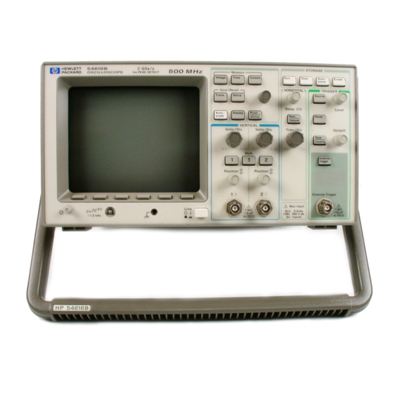
- Page 2 A General-Purpose Oscilloscope The HP 54615B, HP 54616B, and HP 54616C oscilloscopes offer exceptional waveform viewing and measurements in a small, lightweight package. These dual channel, 500 MHz bandwidth oscilloscopes are designed for use in labs where high speed analog and digital circuits are being tested.
- Page 3 Accessories supplied • Two 1.5 meter, 10:1 Rugged 500 MHz Passive Probes (HP 10073A) • Power cord for country of destination • This User and Service Guide • Programmer’s Guide with Microsoft Windows 3.1 Help file, ascii help file, and sample programs.
- Page 4 Options available • Option 001 RS-03 Magnetic Interference Shielding Added to CRT (HP 54615B and HP 54616B only) • Option 002 RE-02 Display Shield Added to CRT (HP 54615B and HP 54616B only) • Option 005 Enhanced TV/Video Trigger •...
-
Page 5: In This Book
Operating your Oscilloscope Using Option 005 Enhanced TV/Video Trigger This is the User and Service Guide for the HP 54615B, HP 54616B, and HP 54616C Oscilloscopes. This guide Service contains five chapters. First Time Users Chapter 1 is a quick... -
Page 7: Table Of Contents
To set up the time base 1–11 To trigger the oscilloscope 1–13 To use roll mode 1–16 Using Color (HP 54616C only) 1–17 To select the color palettes and observe colors 1–18 To print in color 1–20 2 Operating Your Oscilloscope To use delayed sweep 2–3... - Page 8 To verify Vertical Output on Option 005 4–18 Adjusting the Oscilloscope 4–21 To adjust the power supply 4–22 To perform the self-calibration 4–25 To adjust the high-frequency pulse response 4–27 To adjust the display (HP 54615B/16B only) 4–29 To adjust the Option 005 offset (R15) 4–31 Contents-2...
- Page 9 Contents Troubleshooting the Oscilloscope 4–32 To construct your own dummy load 4–33 To check out the oscilloscope 4–34 To clear error messages 4–37 To check the Low Voltage Power Supply 4–41 To run the internal self-tests 4–42 To troubleshoot Option 005 4–45 Replacing Parts in the Oscilloscope 4–45 To replace an assembly 4–46 To remove the fan 4–47...
- Page 10 Advanced Functions 5–8 Power Requirements 5–8 General 5–9 (HP 54615B and HP 54616B only) General 5–11 (HP 54616C only) General (HP 54615B, HP 54616B, and HP 54616C) 5–12 Option 005 General Performance Characteristics 5–13 Option 005 Trigger System 5–14 Glossary Index Contents-4...
-
Page 11: The Oscilloscope At A Glance
Perform self-calibration first For the oscilloscope to perform most accurately in the ambient temperature where it will be used, the self-calibration procedure described on page 4-25 should first be performed. Allow the unit to operate for at least 30 minutes before performing the self-calibration. - Page 12 The Oscilloscope at a Glance One of the first things you will want to do with your new oscilloscope is to become acquainted with its front panel. Therefore, we have written the exercises in this chapter to familiarize you with the controls you will use most often.
- Page 13 Figure 1–1 Storage keys General controls Trigger controls External Channel trigger controls control External Channel trigger input inputs Horizontal Front Panel Controls controls Delayed sweep is on, 200 ns/div Main sweep 500 µs/div Figure 1–2 Sample rate display Autostore is on (Main/Delayed) Auto triggered, positive slope,...
- Page 14 Figure 1–3 Press this key To obtain this menu Press this key To obtain this menu Softkey Menu Reference 1–4...
-
Page 15: To Connect A Signal To The Oscilloscope
To connect a signal to the oscilloscope To connect a signal to the oscilloscope The HP 54615B is a two-channel, 500 MHz bandwidth, 1 GSa/s sample rate oscilloscope with an external trigger input. The HP 54616Band HP 54616C are two-channel, 500 MHz bandwidth, 2 GSa/s sample rate oscilloscopes with an external trigger input. - Page 16 The Oscilloscope at a Glance To connect a signal to the oscilloscope • To set the input impedance, press . Select the desired Input Ω Ω impedance of 50 or 1M • To set the probe attenuation factor press . Select the Next Menu softkey.
-
Page 17: To Display A Signal Automatically
The Oscilloscope at a Glance To display a signal automatically To display a signal automatically The oscilloscope has an Autoscale feature that automatically sets up the oscilloscope to best display the input signal. Using Autoscale requires signals with a frequency greater than or equal to 50 Hz and a duty cycle greater than 0.5%. -
Page 18: To Set Up The Vertical Window
The Oscilloscope at a Glance To set up the vertical window To set up the vertical window The following exercise guides you through the vertical keys, knobs, and status line. Center the signal on the display with the Position knob. The Position knob moves the signal vertically, and it is calibrated. - Page 19 The Oscilloscope at a Glance To set up the vertical window Change the vertical setup and notice that each change affects the status line differently. You can quickly determine the vertical setup from the status line in the display. • Change the vertical sensitivity with the Volts/Div knob and notice that it causes the status line to change.
-
Page 20: To Expand The Vertical Signal
The Oscilloscope at a Glance To expand the vertical signal To expand the vertical signal When changing the Volts/Div for analog channels, you can have the signal expand (or compress) about the center screen or about the ground point. • To expand the signal about center screen, press Print/Utility Then select... -
Page 21: To Set Up The Time Base
The Oscilloscope at a Glance To set up the time base To set up the time base The following exercise guides you through the time base keys, knobs, and status line. Turn the Time/Div knob and notice the change it makes to the status line. - Page 22 The Oscilloscope at a Glance To set up the time base • Turn the Delay knob and notice that its value is displayed in the status line. The Delay knob moves the main sweep horizontally, and it pauses at 0.00 s, mimicking a mechanical detent. At the top of the graticule is a ) symbol and an open triangle ( ∇...
-
Page 23: To Trigger The Oscilloscope
The Oscilloscope at a Glance To trigger the oscilloscope To trigger the oscilloscope The following exercise guides you through the trigger keys, knobs, and status line. Turn the trigger Level knob and notice the changes it makes to the display. As you turn the Level knob or press a trigger menu key, for a short time two things happen on the display. - Page 24 The Oscilloscope at a Glance To trigger the oscilloscope • Press Mode A softkey menu appears on the display with five trigger mode choices. • Toggle the Single and TV softkeys and notice that they affect the status line differently. (You can only select TV if the trigger source is either channel 1 or 2.) When the oscilloscope is triggering properly, the trigger mode portion of the status line is blank.
- Page 25 The Oscilloscope at a Glance To trigger the oscilloscope • Press Slope/Coupling A softkey menu appears on the display. If you selected Auto level, Auto, Normal, or Single as a trigger mode, six softkey choices are displayed. If you selected TV as a trigger source, five other softkey choices are available.
-
Page 26: To Use Roll Mode
• Roll mode is available at sweep speeds of 200 ms/div and slower for the HP 54615B and HP 54616B. Roll mode is available at sweep speeds of 500 ms/div and slower for the HP 54616C. -
Page 27: Using Color (Hp 54616C Only)
Using Color (HP 54616C only) With the HP 54616C color oscilloscope, you can select any of the seven available color palettes to assign colors to channels, cursors, stored waveforms, and text. The seven color palettes allow additional customization, which allows you to easily distinguish between channel waveforms. -
Page 28: To Select The Color Palettes And Observe Colors
The Oscilloscope at a Glance To select the color palettes and observe colors To select the color palettes and observe colors Press . The name of the selected palette appears Display under the softkey. Palette Press the softkey. Continue to cycle through the palettes and Palette observe colors applied to the cursors, waveforms, and softkeys. - Page 29 The Oscilloscope at a Glance To select the color palettes and observe colors The following table shows the color palettes and the palette colors mapped to the display components. Table 1-1 Color Palettes and Mapping of Colors to Display Components Palette Color Display Component...
-
Page 30: To Print In Color
Print Screen softkey. The current display will be sent out the parallel port to the HP DeskJet color printer attached to your oscilloscope, and printed in color. See also Refer to the Interface Modules for HP 54600-Series Instuments I/O Function Guide for other input/output and printing functions. -
Page 31: Operating Your Oscilloscope
Operating Your Oscilloscope... - Page 32 Operating Your Oscilloscope By now you are familiar with the , and VERTICAL, HORIZONTAL TRIGGER groups of the front-panel keys. You should also know how to determine the setup of the oscilloscope by looking at the status line. If you are unfamiliar with this information, we recommend you read chapter 1, "The Oscilloscope at a Glance."...
-
Page 33: To Use Delayed Sweep
Operating Your Oscilloscope To use delayed sweep To use delayed sweep Delayed sweep is a magnified portion of the main sweep. You can use delayed sweep to locate and horizontally expand part of the main sweep for a more detailed (high resolution) analysis of signals. The following steps show you how to use delayed sweep. - Page 34 Operating Your Oscilloscope To use delayed sweep Since both the main and delayed sweeps are displayed, there are half as many vertical divisions so the vertical scaling is doubled. Notice the changes in the status line. • To display the delay time of the delayed sweep, either press or turn the delay knob.
- Page 35 Operating Your Oscilloscope To use delayed sweep Figure 2-2 shows the time reference set to center. Notice that the markers expand around the area of interest. You can place the markers over the area of interest with the delay knob, then expand the delayed sweep with the time base knob to increase the resolution.
-
Page 36: To Use Storage Oscilloscope Operation
Operating Your Oscilloscope To use storage oscilloscope operation To use storage oscilloscope operation There are four front-panel storage keys. They are white instant action keys that change the operating mode of the oscilloscope. The following steps demonstrate how to use these storage keys. Connect a signal to the oscilloscope and obtain a stable display. - Page 37 Operating Your Oscilloscope To use storage oscilloscope operation Using the position knob in the Vertical section of the front panel, move the trace up and down about one division. Notice that the last acquired waveform is in full bright and the previously acquired waveforms are displayed in half bright.
-
Page 38: To Capture A Single Event
Operating Your Oscilloscope To capture a single event To capture a single event To capture a single event, you need some knowledge of the signal in order to set up the trigger level and slope. For example, if the event is derived from TTL logic, a trigger level of 2 volts should work on a rising edge. - Page 39 Operating hint With display vectors on, the maximum single-shot bandwidth is: HP 54615B – 250 MHz for single- and two-channel operation (1 GSa/s, normal display, display vectors on.) HP 54616B/16C – 500 MHz for single- and two-channel operation (2 GSa/s, normal display, display vectors on.)
-
Page 40: To Capture Glitches Or Narrow Pulses
Operating Your Oscilloscope To capture glitches or narrow pulses To capture glitches or narrow pulses A glitch is a rapid change in the waveform that is usually narrow as compared to the waveform. This oscilloscope has two modes of operation that you can use for glitch capture: peak detect and Autostore. - Page 41 Operating Your Oscilloscope To capture glitches or narrow pulses Autostore operating hints Use Autostore for the following cases: • Waveforms that are changing. • Waveforms that you want to view and compare with stored waveforms. • Narrow pulses or glitches that occur infrequently. •...
-
Page 42: To Trigger On A Complex Waveform
Operating Your Oscilloscope To trigger on a complex waveform To trigger on a complex waveform The difficulty in viewing a complex waveform is triggering on the signal. Figure 2-3 shows a complex waveform that is not synchronized with the trigger. The simplest trigger method is to trigger the oscilloscope on a sync pulse that is associated with the waveform. - Page 43 Operating Your Oscilloscope To trigger on a complex waveform Figure 2-3 Stable trigger, but the waveform is not synchronized with the trigger Figure 2-4 Holdoff synchronizes the waveform with the trigger In Figure 2-4, the holdoff is set to about 25 µs (the duration of the pattern.) 2–13...
-
Page 44: To Make Frequency Measurements Automatically
Operating Your Oscilloscope To make frequency measurements automatically To make frequency measurements automatically The automatic measurement capability of the oscilloscope makes frequency measurements easy, as the following steps demonstrate. Connect a signal to the oscilloscope and obtain a stable display. Press Time A softkey menu appears with six softkey choices. - Page 45 Operating Your Oscilloscope To make frequency measurements automatically If the Show Meas softkey is turned on, cursors are displayed on the waveform that show the measurement points for the right-most measurement result. If you select more than one measurement, you can show a previous measurement by reselecting the measurement.
-
Page 46: To Make Time Measurements Automatically
Operating Your Oscilloscope To make time measurements automatically To make time measurements automatically You can measure the following time parameters with the oscilloscope: frequency, period, duty cycle, width, rise time, and fall time. The following exercise guides you through the Time keys by making a rise time measurement. - Page 47 Operating Your Oscilloscope To make time measurements automatically Press Time A softkey menu appears with six softkey choices. Three of the softkeys are time measurement functions. Source Selects a channel for the time measurement. Time Measurements Three time measurement choices are available: Freq (frequency), Period, and Duty Cy (duty cycle).
- Page 48 Operating Your Oscilloscope To make time measurements automatically Time Measurements Four additional time measurement choices are available; +Width, -Width, Rise Time, and Fall Time. Width measurements are made at the 50% levels, whereas rise time and fall time measurements are made at the 10% to 90% levels.
-
Page 49: To Make Voltage Measurements Automatically
Operating Your Oscilloscope To make voltage measurements automatically To make voltage measurements automatically You can measure the following voltage parameters automatically with the oscilloscope: peak-to-peak, average, rms, maximum, minimum, top, and base. The following exercise guides you through the Voltage keys by making an rms voltage measurement. - Page 50 Operating Your Oscilloscope To make voltage measurements automatically Connect a signal to the oscilloscope and obtain a stable display. Press Voltage A softkey menu appears with six softkey choices. Three of the softkeys are voltage measurement functions. Source Selects a channel for the voltage measurement. Voltage Measurements Three voltage measurement choices are available: Vp-p, Vavg, and Vrms The measurements are determined by voltage histograms of the signal.
- Page 51 Operating Your Oscilloscope To make voltage measurements automatically Press the softkey. Vrms The oscilloscope automatically measures the rms voltage and displays the result on the display. The oscilloscope makes automatic measurements on the first pulse or period in the display. If a cycle of the waveform cannot be found as shown in the delayed window in figure 2-10, the measurement is made using the delayed window as the cycle.
- Page 52 Operating Your Oscilloscope To make voltage measurements automatically Press the Next Menu softkey. Another voltage measurement softkey menu appears with six additional choices. Four of the softkeys are voltage measurement functions. Show Meas (show measurement) Displays the horizontal and vertical cursors that show where the measurement was taken on the signal.
-
Page 53: To Make Cursor Measurements
Operating Your Oscilloscope To make cursor measurements To make cursor measurements The following steps guide you through the front-panel Cursors key. You can use the cursors to make custom voltage or time measurements on the signal. Examples of custom measurements include rise time measurements from reference levels other than 10-90%, frequency and width measurements from levels other than 50%, channel-to-channel delay measurements, and voltage measurements. - Page 54 Operating Your Oscilloscope To make cursor measurements Figure 2-11 Cursors used to measure pulse width at levels other then the 50% points Figure 2-12 Cursors used to measure the frequency of the ringing on a pulse 2–24...
- Page 55 Operating Your Oscilloscope To make cursor measurements Figure 2-13 Cursors used to make channel-to-channel delay measurements Figure 2-14 The cursors track delayed sweep. Expand the display with delayed sweep, then characterize the event of interest with the cursors. 2–25...
- Page 56 Operating Your Oscilloscope To make cursor measurements Figure 2-15 Pressing t1 and t2 softkeys simultaneously causes the time cursors to move together when the cursor knob is adjusted. Figure 2-16 By moving the time cursors together, you can check for pulse width variations in a pulse train, as figures 2-15 and 2-16 show.
-
Page 57: To Remove Cabling Errors From Time Interval Measurements
Operating Your Oscilloscope To remove cabling errors from time interval measurements To remove cabling errors from time interval measurements When measuring time intervals in the nanosecond range, small differences in cable length can totally obscure the measurement. The following exercise shows how to remove errors that different cable lengths or characteristics introduce to your measurement. -
Page 58: To View Asynchronous Noise On A Signal
Operating Your Oscilloscope To view asynchronous noise on a signal To view asynchronous noise on a signal The following exercise shows how to use the oscilloscope to view asynchronous noise on a signal that is not synchronous to the period of the waveform. - Page 59 Operating Your Oscilloscope To view asynchronous noise on a signal Press Autostore Notice that STORE is displayed in the status line. Set the Trigger Mode to Normal, then adjust the trigger level into the noise region of the signal. Decrease the sweep speed for better resolution of the asynchronous noise.
-
Page 60: To Reduce The Random Noise On A Signal
Operating Your Oscilloscope To reduce the random noise on a signal To reduce the random noise on a signal If the signal you are applying to the oscilloscope is noisy (figure 2-21), you can set up the oscilloscope to reduce the noise on the waveform (figure 2-22). - Page 61 Operating Your Oscilloscope To reduce the random noise on a signal Low frequency reject (LF Reject) adds a high pass filter with the 3-dB point at 50 kHz (see figure 2-20). Use LF reject to remove low frequency signals such as power line noise from the trigger path.
- Page 62 Operating Your Oscilloscope To reduce the random noise on a signal Use averaging to reduce noise on the displayed waveform. To use averaging follow these steps. • Press , the press the Average softkey. Display Notice that Av appears in the status line. •...
-
Page 63: To Save Or Recall Traces
Operating Your Oscilloscope To save or recall traces To save or recall traces The oscilloscope has two pixel memories for storing waveforms. The following exercise guides you through how to store and recall waveforms from pixel memories. Connect a signal to the oscilloscope and obtain a stable display. Press Trace A softkey menu appears with five softkey selections. -
Page 64: To Save Or Recall Front-Panel Setups
Operating Your Oscilloscope To save or recall front-panel setups The automatic measurement functions do not operate on stored traces. Remember, the stored waveforms are pictorial information rather than stored data. • If you have not changed the oscilloscope setup, use the cursors to make the measurements. -
Page 65: To Reset The Instrument Setup
Operating Your Oscilloscope To reset the instrument setup To reset the instrument setup To reset the instrument to the default factory-preset configuration, press Setup Press the Default Setup softkey. To reset the instrument to the configuration that was present before pressing Autoscale, press the Undo Autoscale softkey. -
Page 66: To Use The Xy Display Mode
Operating Your Oscilloscope To use the XY display mode To use the XY display mode The XY display mode converts the oscilloscope from a volts versus time display to a volts versus volts display. You can use various transducers so the display could show strain versus displacement, flow versus pressure, volts versus current, or voltage versus frequency. - Page 67 Operating Your Oscilloscope To use the XY display mode XY display mode operating hint Before entering xy display mode, center both channels on screen in the main sweep and adjust sweep speed to obtain greater than or equal to 1 cycle of the lowest frequency input signal on screen.
- Page 68 Operating Your Oscilloscope To use the XY display mode Move the Y1 and Y2 cursors to the center of the signal. Again, note the ∆Y value. Figure 2-25 Calculate the phase difference using formula below. second ∆ Y 143.8 sin θ = first ∆Y 300.0 θ...
- Page 69 Operating Your Oscilloscope To use the XY display mode Figure 2-26 Signals are 90° out of phase Figure 2-27 Signals are in phase 2–39...
-
Page 70: To Analyze Video Waveforms
Operating Your Oscilloscope To analyze video waveforms To analyze video waveforms Enhanced TV/Video Trigger This section discusses basic TV video triggering. If you have Option 005 Enhanced TV/Video Trigger installed in your oscilloscope, refer to Chapter 3 "Using Option 005 Enhanced TV/Video Trigger." The TV sync separator in the oscilloscope has an internal clamp circuit. - Page 71 Operating Your Oscilloscope To analyze video waveforms Set the time base to 200 µs/div, then center the signal on the display with the delay knob (delay about 800 µs). Press , then press the Delayed softkey. Main/Delayed Set the delayed sweep to 20 µs/div, then set the expanded portion over the VITS (delay about 920 µs, dependent on broadcast channel).
- Page 72 Delay in TV line units hint The oscilloscope has the ability to display delay in TV-line units. Using the TV field trigger mode activates this line-counting feature. When Field 1 or Field 2 is selected as the trigger source, delay can be set in terms of time or line number. Both-fields triggering in the oscilloscope hint The oscilloscope can trigger on the vertical sync pulse in both TV fields at the same time.
-
Page 73: Using Option 005 Enhanced Tv/Video Trigger
Using Option 005 Enhanced TV/Video Trigger... - Page 74 Using Option 005 Enhanced TV/Video Trigger Basic TV/video triggering This section discusses Enhanced TV/Video triggering. If you do not have Option 005 installed in your oscilloscope, refer to the last section in Chapter 2 "To analyze video waveforms" for basic TV triggering procedures. You can use the Option 005 Enhanced TV/Video trigger with your oscilloscope.
- Page 75 Using Option 005 Enhanced TV/Video Trigger Option 005 gives you an Enhanced TV/Video Trigger for the oscilloscope, allowing highly detailed analysis of TV waveforms. This option offers: • NTSC, PAL, PAL-M, SECAM and generic video formats • Video autoscale • IRE graticule and IRE cursor readout •...
-
Page 76: To Select Tv Display Grid
Provide correct source matching Many TV signals are produced from 75Ω sources. To provide correct matching to these sources, an HP 11094B 75Ω load is included as an accessory. For oscilloscopes that have selectable input impedance, the 1 MΩ input should be used with the 75Ω... -
Page 77: To Trigger On A Specific Line Of Video
Using Option 005 Enhanced TV/Video Trigger To trigger on a specific line of video To trigger on a specific line of video TV triggering requires greater than 1/4 division of sync amplitude, either channel 1 or channel 2 as the trigger source. Turning the trigger level knob in TV trigger does not change the trigger level because the trigger level is automatically set to the sync pulse tips. - Page 78 Using Option 005 Enhanced TV/Video Trigger To trigger on a specific line of video Figure 3-1 Triggering on Line 71 Table 3-1 Line Numbers per Field for Each TV Standard TV Standard Field 1 Field 2 Alt Fld NTSC 1 to 263 1 to 262 1 to 262 1 to 313...
-
Page 79: To Trigger On All Tv Line Sync Pulses
Using Option 005 Enhanced TV/Video Trigger To trigger on all TV line sync pulses To trigger on all TV line sync pulses To quickly find maximum video levels, you could trigger on all TV line sync pulses. When All Lines is selected as the TV trigger mode, the oscilloscope will trigger on the first line that it finds when the acquisition starts. -
Page 80: To Trigger On A Specific Field Of The Video Signal
Using Option 005 Enhanced TV/Video Trigger To trigger on a specific field of the video signal To trigger on a specific field of the video signal To examine the components of a video signal, trigger on either Field 1 or Field 2. -
Page 81: To Trigger On All Fields Of The Video Signal
Using Option 005 Enhanced TV/Video Trigger To trigger on all fields of the video signal To trigger on all fields of the video signal To quickly and easily view transitions between fields, or to find the amplitude differences between the fields, use the All Fields trigger. The oscilloscope will trigger on the first field it finds at the start of acquisition. -
Page 82: To Trigger On Odd Or Even Fields
Using Option 005 Enhanced TV/Video Trigger To trigger on odd or even fields To trigger on odd or even fields To check the envelope of your video signals, or to measure worst case distortion, trigger on the odd or even fields. When Field 1 is selected, the oscilloscope triggers on color fields 1 or 3. - Page 83 Using Option 005 Enhanced TV/Video Trigger To trigger on odd or even fields If a more detailed analysis is required, then only one color field should be selected to be the trigger. You can do this by using the oscilloscope’s holdoff control.
-
Page 84: To Make Cursor Measurements
Using Option 005 Enhanced TV/Video Trigger To make cursor measurements To make cursor measurements The following steps guide you through the front-panel Cursors key. You can use the cursors to make custom voltage or time measurements on the signal. Examples of custom measurements include rise time measurements from reference levels other than 10-90%, frequency and width measurements from levels other than 50%, channel-to-channel delay measurements, and voltage measurements. - Page 85 Using Option 005 Enhanced TV/Video Trigger To make cursor measurements Figure 3-7 Color Sync measured with the cursors as 40 IRE 3–13...
-
Page 86: To Use Delayed Sweep
Using Option 005 Enhanced TV/Video Trigger To use delayed sweep To use delayed sweep Delayed sweep is a magnified portion of the main sweep. You can use delayed sweep to locate and horizontally expand part of the main sweep for a more detailed (high resolution) analysis of signals, for example multi-burst frequencies. - Page 87 Using Option 005 Enhanced TV/Video Trigger To use delayed sweep Figure 3-8 Modulated staircase or 5-step, measuring sync pulse fall time with delayed sweep Figure 3-9 Windowed frequency measurement in a multi-burst by use of delayed sweep 3–15...
-
Page 88: To Analyze Video Waveforms With Option 005
Using Option 005 Enhanced TV/Video Trigger To analyze video waveforms with Option 005 To analyze video waveforms with Option 005 The combination of the TV trigger, delayed sweep, and automatic measurements allow this oscilloscope to precisely analyze video waveforms. There is no need for external clamping to obtain a stable trigger when you are viewing unclamped video signals. - Page 89 Using Option 005 Enhanced TV/Video Trigger To analyze video waveforms with Option 005 Set the time base to 200 µs/div, then center the signal on the display with the delay knob (delay about 800 µs). Press , then press the softkey.
-
Page 90: To Window In On Harmonic Distortion Using Fft
However, in the frequency domain, these harmonics are very apparent. Your oscilloscope, when used with the HP 54657A, HP 54658A, or HP 54659B Measurement/Storage module, have the ability to perform frequency domain analysis on a time domain waveform using the Fast Fourier Transform (FFT). - Page 91 Using Option 005 Enhanced TV/Video Trigger To window in on harmonic distortion using FFT The FFT function then shows the harmonic content of the subcarrier in the figure below. Had the time/division and delays controls not been used to zoom in on the desired subcarrier, the entire video signal (with many frequency components) would have appeared in the frequency domain display.
-
Page 92: To Connect To Other Instruments
Using Option 005 Enhanced TV/Video Trigger To connect to other instruments To connect to other instruments The rear panel outputs provide an easy way to connect your Option 005-equipped oscilloscope to other instruments such as spectrum analyzers or frequency counters. To use a frequency counter: Connect the vertical output of the oscilloscope to the counter’s input. -
Page 93: Service
Verifying Oscilloscope Performance 4–5 Adjusting the Oscilloscope 4–21 Troubleshooting the Oscilloscope 4–32 Replacing Parts in the Oscilloscope 4–45 Service... - Page 94 Service If the oscilloscope is under warranty, you must return it to Hewlett-Packard for all service work covered by the warranty. See "To return the oscilloscope to Hewlett-Packard," on page 4-4. If the warranty period has expired, you can still return the oscilloscope to Hewlett-Packard for all service work.
- Page 95 1 to 500 MHz ±3% accuracy Power meter and HP 436A and HP 8482A Power sensor Power supply 14 mV to 35 Vdc, 0.1 mV resolution HP 6114A Rise time ≤ 700 ps Pulse generator HP 8131A Power splitter Outputs differ < 0.15 dB...
-
Page 96: To Return The Oscilloscope To Hewlett-Packard
You can use either the original shipping containers, or order materials from an HP Sales Office. Otherwise, pack the oscilloscope in 3 to 4 inches of shock-absorbing material to prevent movement inside the shipping container. -
Page 97: Verifying Oscilloscope Performance
Verifying Oscilloscope Performance This section shows you how to verify the electrical performance of the oscilloscope, using the performance characteristics in chapter 5 as the standard. The characteristics checked are calibrator, voltage measurement accuracy, bandwidth, horizontal accuracy, and trigger sensitivity. You should verify the performance of the oscilloscope when you first receive it, and every 12 months or after 2,000 hours of operation. -
Page 98: To Check The Output Of The
CALIBRATOR a multimeter and an oscilloscope. The is used for CALIBRATOR self-calibration of the HP 54615B, HP 54616B, and HP 54616C. The accuracy of the is not specified, but it must be within the test limits to CALIBRATOR provide for accurate self-calibration. - Page 99 Service Verifying Oscilloscope Performance Press any key once to advance the test. The multimeter should read 5.000 V ± 10 mV. If the result is not within the test limits, see "Troubleshooting the oscilloscope," on page 4-32. Connect an oscilloscope to the rear-panel connector.
-
Page 100: To Verify Voltage Measurement Accuracy
8 divisions times the V/div setting. Table 4-3 Equipment Required Equipment Critical specifications Recommended Model/Part Power supply 14 mV to 35 Vdc, 0.1 mV resolution HP 6114A Digital multimeter Better than 0.01% accuracy HP 34401A Cable BNC, Qty 2 HP 10503A Shorting cap HP 1250-0774... - Page 101 Service Verifying Oscilloscope Performance Connect the power supply to the oscilloscope and to the multimeter, using the BNC tee and cables. Adjust the power supply output so that the multimeter reading displays the first Power supply setting value in table 4-4. Wait a few seconds for the measurment to settle.
-
Page 102: To Verify Bandwidth
Signal generator 1 to 500 MHz at 200 mV HP 8656B opt 001 1 to 500 MHz ±3% accuracy Power meter and HP 436A and HP 8482A Power Sensor Power splitter Outputs differ by < 0.15 dB HP 11667B Cable... - Page 103 Service Verifying Oscilloscope Performance Connect the equipment. Connect the signal generator to the input of the power splitter. Connect the power sensor to one output of the power splitter, and connect channel 1 of the oscilloscope to the other power splitter output.
- Page 104 Service Verifying Oscilloscope Performance Change the time base to 5 ns/div. Wait a few seconds for the measurement to settle (the Av letters in the status line indicate how much of the averaging process is finished by turning to inverse video as the oscilloscope performs averaging), then note the Vp-p reading from the bottom of the display.
-
Page 105: To Verify Horizontal ∆T And 1/∆T Accuracy
Stability 5 ppm after 1/2 hour TG 501A and TM 503B Cable BNC, 3 feet HP 10503A Connect the time mark generator to channel 1. Then, set the time mark generator for 0.1 ms markers. Setup the oscilloscope. , then press the Default Setup softkey. - Page 106 Service Verifying Oscilloscope Performance Press , then press the Freq and Period softkeys. Time You should measure the following: Frequency 1 MHz, test limits are 995.8 kHz to 1.0042 MHz. Period 1 µs, test limits are 995.9 ns to 1.004 µs. If the measurements are not within the test limits, see "Troubleshooting the Oscilloscope,"...
-
Page 107: To Verify Trigger Sensitivity
Power splitter Outputs differ < 0.15 dB HP 11667B Cable BNC, Qty 3 HP 10503A Adapter N (m) to BNC (f), Qty 3 HP 1250-0780 1 to 500 MHz ±3% Power meter and HP 436A and HP 8482A Power sensor 4-15... - Page 108 Service Verifying Oscilloscope Performance Press , then press the softkey. Internal Trig Default Setup Setup Sensitivity Connect the signal generator to channel 1. Verify the trigger sensitivity at 100 MHz and 0.5 divisions. Set the signal generator to 100 MHz and about 50 mV. Press Autoscale Press...
- Page 109 If the test fails, refer to "Troubleshooting the Oscilloscope" on page 4-32. Change the signal generator frequency to 100 MHz at output amplitude of 75 mV p-p, as measured with the HP 54615B/16B/16C (channel 1). Press , then the softkey Vp-p Voltage Set Time/div to 10 ns/div.
-
Page 110: To Verify Vertical Output On Option 005
~90 mVp-p into 50Ω with a full screen input. Table 4-8 Equipment Required Equipment Critical specifications Recommended Model/Part Signal generator 1 to 500 MHz at 200 mV HP 8656B opt 001 Cable BNC, 48 inch HP 10503A Cable Type N (m), 24 inch HP 11500B Adapter... - Page 111 HP 54615B/54616B/54616C Performance Test Record Serial No. ______________________________________ Test by____________________________ Test Interval ____________________________________ Work Order No._____________________ Recommended Next Testing _______________________ Temperature _______________________ Calibrator Output Nominal Test Limits Result 0 µV –500 µV to +500 µV _____________ 4.990 V to 5.010 V...
- Page 112 4-20...
-
Page 113: Adjusting The Oscilloscope
Adjusting the Oscilloscope This section explains how to adjust the oscilloscope so that it is at optimum operating performance. You should perform the hardware adjustments and Self Cal periodically as indicated below. • Hardware adjustments at 12 months or 2,000 hours of operation •... -
Page 114: To Adjust The Power Supply
Critical specifications Recommended Model/Part 0.1 mV resolution, accuracy ±0.05% Digital multimeter HP 34401A Set up the oscilloscope for the voltage adjustment. Turn off the oscilloscope and disconnect power cable. Remove the cover from the oscilloscope as described in "To replace an assembly"... - Page 115 Service Adjusting the Oscilloscope Measure the power supply voltages at E10 through E15 on the system board. The test points are not marked on the system board; see figure below for location of test points. Make sure that the voltage measurements are within the following tolerances. Power Supply Voltage Tolerances Supply Voltage Tolerance...
- Page 116 Service Adjusting the Oscilloscope If the +5.1 V measurement is out of tolerance, adjust the +5.1 V adjustment on the power supply; if the –5.25 V measurement is out of tolerance, adjust the –5.25 V adjustment on the power supply (see figure below). The ±15.75 V supplies are not adjustable and are dependent upon the +5.1 V supply.
-
Page 117: To Perform The Self-Calibration
Table 4-10 Equipment Required Equipment Critical specifications Recommended Model/Part Cable BNC, 3 feet HP 10503A Cable BNC, 9 inches, Qty 2 HP 10502A Adapter BNC tee (m) (f) (f) HP 1250-0781 Adapter BNC (f-f) - Page 118 1 and channel 2, then to channel 1 and external trigger, and finally to channel 2 and and external trigger. Make sure you use the HP 10502A cables to ensure equal cable lengths. Press the softkey to start the delay self calibration.
-
Page 119: To Adjust The High-Frequency Pulse Response
Table 4-11 Equipment Required Equipment Critical specifications Recommended Model/Part Rise time ≤ 700 ps Pulse generator HP 8131A Cable 50Ω BNC (m-m) HP 10503A Press , press the Default Setup softkey, then set the Setup oscilloscope and pulse generator as indicated below. - Page 120 Adjust the channel 1 high-frequency pulse response for an % overshhot of 5% mininum to 7% maximum. If a low loss 50Ω cable is used (such as HP 8120-4949), the % overshoot should be 6% minimum to 8% maximum.) Repeat steps 2 through 10 substituting Channel 2 for Channel 1 and ∆V(2) for ∆V(1).
-
Page 121: To Adjust The Display (Hp 54615B/16B Only)
Service Adjusting the Oscilloscope To adjust the display (HP 54615B/16B only) There are no adjustments on the HP 54616C color display – if the display fails, replace the display assembly. The display adjustments are optional and normally do not require adjustment. - Page 122 Service Adjusting the Oscilloscope Adjust HB Cont (half bright contrast) for the best contrast between the half bright and full bright blocks. You can readjust Sub Bri, intensity control, and HB Cont to suit your individual preference. Press any key to continue to the next test pattern. Then, adjust H.Hold (horizontal hold) to center the display horizontally.
-
Page 123: To Adjust The Option 005 Offset (R15)
Equipment Required Critical Specification Recommended Model/Part 0.1 mV resolution, accuracy ±0.05% Digital Multimeter HP 34401A Adapter BNC (m) to dual banana post HP 10110B Set up the oscilloscope for the voltage adjustment. Turn off the oscilloscope. Remove the cabinet from the oscilloscope. -
Page 124: Troubleshooting The Oscilloscope
Equipment Required Equipment Critical specifications Recommended model/part Accuracy ±0.05%, 1 mV resolution Digital multimeter HP 34401A Oscilloscope 100 MHz, 1 MΩ input R HP 54600 Dummy load Compatible with power supply see note 1 below See page 4-33 to construct your own dummy load. -
Page 125: To Construct Your Own Dummy Load
Service Troubleshooting the Oscilloscope To construct your own dummy load Obtain a connector compatible with the connector J3 on the Low Voltage Power Supply (see figure below). Connect the following load resistors to the connector. +5.1 V requires a 4 A load, 1.3 Ω and 20.4 W on pins 9–12. –5.25 V requires a 3 A load, 1.75 Ω... -
Page 126: To Check Out The Oscilloscope
Disconnect the power cord, then remove the cover. Connect the power cord, then turn on the oscilloscope. If the display comes on after a few seconds, (HP logo and copyright text, followed by a graticule with text at top of the display) go to "To check the Low Voltage Power Supply,"... - Page 127 Service Troubleshooting the Oscilloscope Disconnect the ribbon cable from the display board, then check the following signals on the system board. Table 4-15 Signals from U609 (HP 54615B and HP 54616B) Signal Name Frequency Pulse width Voltage 38.0 µs U817 Pin 7 19.72 kHz...
- Page 128 Service Troubleshooting the Oscilloscope Low Voltage Power Supply Voltage Tolerances Supply Voltage Tolerance +5.1 V ±153 mV (+4.947 V to +5.253 V) ±158 mV (–5.092 V to –5.408 V) –5.25 V +15.75 V +1.260 V, –787 mV (+14.963 V to +17.010 V) −...
-
Page 129: To Clear Error Messages
Hold the menu key down until the message "Key-down power-up executed" or "Keydown power sequence initiated ..." is displayed. c If the original fail message still appears, contact your HP Service Center for diagnosis and repair. Setup memories and trace memories are cleared after a keydown powerup is performed. - Page 130 Cycle the power of the oscilloscope. If default horizontal delay calibration factors are loaded and error messages remain, contact your HP service center for diagnosis and repair. If one of the following messages appears on screen: "Results from last vertical calibration: Failed"...
- Page 131 "Channel 2 Acquisition Memory Failed" The first message means an error has developed in the Acquisition memory for channel 1, contact your HP service center for diagnosis and repair. The second message means an error has developed in the Acquisition memory for channel 2, contact your HP service center for diagnosis and repair.
-
Page 132: To Check The Low Voltage Power Supply
Service Troubleshooting the Oscilloscope To check the Low Voltage Power Supply Disconnect the power cord, then set the oscilloscope on its side. Connect the negative lead of the multimeter to a ground point on the oscilloscope. Connect the power cord and turn on the oscilloscope. Measure the power supply voltages at E10 through E15 on the system board. -
Page 133: To Run The Internal Self-Tests
Service Troubleshooting the Oscilloscope To run the internal self-tests Perform the display test (HP 54615B/16B only.) Press Print/Utility Press the Service Menu softkey, then the Self Tst Menu softkey, and then the Display softkey. Do the half bright and full bright squares appear? If yes, continue with the steps below. - Page 134 The test oscilloscope should measure : Vp-p = 900 mV ± 150 mV Vavg = –450 mV ± 75 mV Freq = 2.46 kHz ± 100 Hz (HP 54615B/16B) 2.08 kHz ± 100 Hz (HP 54616C) Are these readings correct? If yes, press any key to continue.
- Page 135 Service Troubleshooting the Oscilloscope Perform the test Press the ROM softkey. Does the display message say "Test Passed"? If yes, go to next test. If not, (the display message says Test Failed) replace the system board. Perform the test. Press the RAM softkey. Does the display message say "Test Passed"? If yes, self-tests are complete.
-
Page 136: To Troubleshoot Option 005
Service Troubleshooting the Oscilloscope To troubleshoot Option 005 To isolate a malfunction to the Option 005 board, do the following: Disconnect the three cables that connect the Option 005 board to the system board. Verify proper oscilloscope operation, as described in this chapter. If the oscilloscope passes the performance verification and the malfunction still occurs when the Option 005 board is reconnected, then you should replace the Option 005 board. -
Page 137: Replacing Parts In The Oscilloscope
Replacing Parts in the Oscilloscope This section contains instructions for removing and ordering replaceable assemblies. Also in this section is a parts list for the assemblies and hardware of the oscilloscope that you can order from Hewlett-Packard. Before working on the oscilloscope, read the safety summary at the back of this book. -
Page 138: To Replace An Assembly
Service Replacing Parts in the Oscilloscope To replace an assembly Refer to the exploded view of the oscilloscope, figure 4-12 (figure 4-14 for Option 005 board), for details on how the oscilloscope fits together. To install an assembly, follow the instructions in reverse order. You will need the following tools to disassemble the oscilloscope: •... -
Page 139: To Remove The Fan
Service Replacing Parts in the Oscilloscope To remove the fan Disconnect the fan cable from the power supply board. Using the T15 TORX driver, remove the three screws that hold the fan to the deck. Fan Orientation When installing the new fan, face the fan to blow air into the oscilloscope To remove the front panel Remove the intensity knob by pulling straight out. - Page 140 Service Replacing Parts in the Oscilloscope When installing the front panel, make sure that the power switch shaft is aligned with its mating hole in the front panel. The front panel swings in to engage the two retainer tabs. Before attempting to engage the retainer tabs, make sure that the six hooks on top of the front panel are fully engaged with their mating holes in the sheet metal.
-
Page 141: To Remove The Display
Service Replacing Parts in the Oscilloscope To remove the display Remove the front panel. Disconnect the ribbon cable and the probe compensation cable from the display. Using the T10 TORX driver, remove the two screws that hold the display to the deck. Make sure that when you reinstall these screws that you use the correct parts. -
Page 142: To Remove The Attenuator
Service Replacing Parts in the Oscilloscope To remove the attenuator Use the following procedure to remove the attenuator assembly. When necessary, refer to other removal procedures. ELECTROSTATIC DISCHARGE! C A U T I O N Use grounded wrist straps and mats when servicing the system board. Electrostatic discharge can damage electronic components. -
Page 143: To Remove And Replace An Acquisition Hybrid
Service Replacing Parts in the Oscilloscope To remove and replace an acquisition hybrid ELECTROSTATIC DISCHARGE! C A U T I O N Use grounded wrist straps and mats when servicing the system board. Electrostatic discharge can damage electronic components. The system board does not need to be removed before replacing an acquisition hybrid. - Page 144 Service Replacing Parts in the Oscilloscope Loosely install the two hex standoffs and two screws through the top plate. Use 5 mm (3/16 in) and T6 torque drivers set to 0.34 Nm (3 in-lbs) to tighten the standoffs and screws in the following sequence. Tighten any standoff or screw to specifications.
-
Page 145: To Remove And Replace A Hybrid Connector
Service Replacing Parts in the Oscilloscope To remove and replace a hybrid connector Two screws (H9) through the hybrid connector (figure 4-9) hold the bottom plate to the underside of the system board. If the hybrid connector is removed, the bottom plate is able to fall away from the board. Disassembly hint The bottom plate may stick to the bottom of the board by itself because of adhesives that fasten an insulator to the plate. -
Page 146: To Remove The Power Supply
Service Replacing Parts in the Oscilloscope To remove the power supply Remove the fan. Disconnect the ground wire (green wire with the yellow stripe) from the deck. Disconnect the ribbon cable from the power supply board. When reconnecting the cable, position both connectors on their mating pieces, then push on one connector at a time. -
Page 147: To Remove The Keyboard
See figure below for positioning the keyboard cable on the HP 54615B and HP 54616B. Figure 4-11 Probe compensation cable Keyboard cable on HP 54615B and HP 54616B Positioning keyboard cable on HP 54615B and HP 54616B 4-55... -
Page 148: To Remove The Handle
Service Replacing Parts in the Oscilloscope To remove the handle • Rotate the handle down until it is just past the last detent position (about 1/2 inch before the handle touches the bottom of the oscilloscope), then pull the sides of the handle out of the cabinet. To remove the Option 005 board Remove the oscilloscope from the cabinet. -
Page 149: To Order A Replacement Part
Service Replacing Parts in the Oscilloscope To order a replacement part The system board is part of an exchange program with Hewlett-Packard. The exchange program allows you to exchange a faulty assembly with one that has been repaired and performance verified by Hewlett-Packard. After you receive the exchange assembly, return the defective assembly to Hewlett-Packard. - Page 150 Within the USA, Hewlett-Packard can supply parts through a direct mail order system. The advantages to the system are, direct ordering and shipment from the HP Parts Center in Mountain View, California. There is no maximum or minimum on any mail order. (There is a minimum amount for parts ordered through a local Hewlett Packard Sales Office when the orders require billing and invoicing.) Transportation costs are prepaid (there is a...
- Page 151 Service Replacing Parts in the Oscilloscope Figure 4-12 A6 and A7 on opposite side of A3. See detail on next page Probe sense nuts mounted on outside of front panel Exploded view of oscilloscope 4-59...
- Page 152 Service Replacing Parts in the Oscilloscope Figure 4–13 MP21 Screws (2) Heatsink Spring MP20 Heatsink MP19 Standoff (2) MP25 Screws (2) Top Plate A6 or A7 Acquisition Hybrid Screws (2) Connector A3 System Board MP24 Bottom Plate A6/A7 Acquisition Hybrid and associated mounting parts 4-60...
- Page 153 Service Replacing Parts in the Oscilloscope Table 4-16 HP 54615B, HP 54616B, and HP 54616C Replaceable Parts Reference HP Part Qty Description Designator Number 0950-2735 Power supply assembly 2090-0316 HP 54615B/16B display assembly 54620-68801 HP 54616C display assembly 54620-69801 HP 54616C exchange display assembly...
- Page 154 1251-2485 Connector dust cover 1400-1581 Cable clamp 54610-41901 Main keypad 54615-94301 HP 54615B front-panel label 54616-94301 HP 54616B front-panel label 54616-94303 HP 54616C front-panel label 54615-94302 HP 54615B handle Label 54616-94302 HP 54616B handle Label 54616-94304 HP 54616C handle Label...
- Page 155 Power cord option 912, Denmark 8120-4600 Power cord option 917, Africa 8120-4754 Power cord option 918, Japan 54630-61602 Power supply cable 54630-61601 HP 54615B/16B display cable 54620-61602 HP 54616C display cable 10073A Passive probes, 10X Option 101 Accessory pouch and front-panel cover. 5041-9411...
- Page 156 Service Replacing Parts in the Oscilloscope Figure 4-14 Exploded view of Option 005 and related oscilloscope parts 4-64...
- Page 157 54602-94305 Label, rear panel video trigger 54602-61601 RF cable 54602-61602 Ribbon cable HP 11094B 75Ω Termination * See the HP 54615B, HP 54616B, and HP 54616C Replaceable Parts table for the HP part number of the A3 System Board. 4-65...
- Page 158 4-66...
- Page 159 Performance Characteristics...
-
Page 160: Vertical System
Performance Characteristics The performance characteristics describe the typical performance of the new HP 54615B, HP 54616B, and HP 54616C oscilloscopes. You will notice that some of the characteristics are marked as tested, these are values that you can verify with the performance tests under "Verifying Oscilloscope Performance,"... -
Page 161: Performance Characteristics Vertical System
Performance Characteristics Vertical System Sensitivity 2 mV/div to 5 V/div ±2.0% of full scale Accuracy Fully calibrated, accuracy ±2.0 % of full scale Verniers 1, 2, 3 Cursor accuracy Single cursor accuracy: vertical accuracy ±1.2% of full scale ±0.5% of position value Dual cursor accuracy: vertical accuracy ±0.4% of full scale Bandwidth limit ≈30 MHz... -
Page 162: Horizontal System
Pretrigger delay (negative time) HP 54615B–The greater of 30 µs or 60 divisions, not to exceed 100 s HP 54616B/16C–The greater of 15 µs or 60 divisions, not to exceed 100 s. Posttrigger delay (from trigger point to start of sweep) The greater of 10 ms or 20,000 divisions, not to exceed 100 s. -
Page 163: Trigger System
Performance Characteristics Trigger System Trigger System Sources Channels 1, 2, line, and external Internal trigger Sensitivity dc to 100 MHz: 0.50 div or 5.0 mV 100 MHz to 500 MHz: 1 div or 10 mV Coupling ac, dc, LF reject, HF reject, and noise reject LF reject attenuates –3 dB for signals below 50 kHz, and HF reject attenuates –3 dB for signals above 50 kHz Modes Auto, Autolevel, Normal, Single, and TV... -
Page 164: Tv Functions
Display HP 54615B/16B — 7-inch raster CRT HP 54616C — 5.8-inch Active Matrix Color LCD Display. The present state-of-the-art for the color displays allows for some pixel defects to be present. The number of these allowed is no more than six active (those which cannot be turned off), and six inactive (those which cannot be turned on). -
Page 165: Acquisition System
500 points (200 ms/div, channel 1 and 2 on, HP 54615B/16B) Single-shot bandwidth HP 54615B – 250 MHz on channels 1 and 2 simultaneously (1 GSa/s, display vectors on) HP 54616B/16C – 500 MHz on channels 1 and 2 simultaneously... -
Page 166: Advanced Functions
Performance Characteristics Advanced Functions Advanced Functions Automatic measurements (measurements are continuously updated) Voltage Vavg, Vrms, Vp-p, Vtop, Vbase, Vmin, Vmax Time Frequency, period, + width, – width, duty cycle, rise time, and fall time Cursor Measurements Four cursors can be positioned on the display to make time voltage measurements. -
Page 167: General (Hp 54615B And Hp 54616B Only)
Performance Characteristics General (HP 54615B and HP 54616B only) General (HP 54615B and HP 54616B only) Environmental The instrument meets or exceeds the environmental requirements of characteristics MIL-T-28800E for Type III, Class 3, Style D equipment as described below. Ambient temperature (Tested to MIL-T-28800E paragraph 4.5.5.1.1) Operating –10 °C to +55 °C... - Page 168 Performance Characteristics General (HP 54615B and HP 54616B only) RE01 Part 5 measured at 15.24 cm and exceptioned from 19kHz to 50 kHz. RE02 Part 2 (limited to 1 GHz) Full limits of class A1C and A1F, with option 002 installed; without option 002 installed 10 dB relaxation, 14 kHz to 100 RS03 Part 2, limited to 1 V/meter from 14 kHz to 1 GHz.
-
Page 169: General (Hp 54616C Only)
Performance Characteristics General (HP 54616C only) General (HP 54616C only) Environmental These general characteristics apply to the HP 54616C only. This instrument characteristics meets Hewlett-Packard’s environmental specifications (section 750) for class B-1 products. Ambient temperature Operating 0 °C to +55 °C Nonoperating –40 °C to +70 °C... -
Page 170: General (Hp 54615B, Hp 54616B, And Hp 54616C)
2 PASS - Temporary degradation, self recoverable. 3 PASS - Temporary degradation, operator intervention required. 4 FAIL - Not recoverable, component damage. Notes: * Code 1 for HP 54616C Code 2 for HP 54615B and HP 54616B Sound Less than 60 dBA Pressure Level... -
Page 171: Option 005 General Performance Characteristics
Performance Characteristics Option 005 General Performance Characteristics Option 005 General Performance Characteristics Video Standards NTSC PAL-M SECAM Generic Video Trigger Modes Line (number) of Field 1 Field 2 Alternate Fields All Lines Field 1 Defined as that field with the 3 lines of vertical sync starting at line 4. -
Page 172: Option 005 Trigger System
Option 005 Trigger System Internal trigger Sensitivity Performance remains unchanged Coupling Performance remains unchanged Modes Performance remains unchanged Holdoff Performance remains unchanged TV triggering Available on channels 1 and 2 only TV line and field 0.5 division of composite sync for stable display External trigger Performance remains unchanged Vertical output... -
Page 173: Glossary
Glossary This glossary is organized into Autostore displays the stored two parts: oscilloscope and waveforms in half bright, and the TV/video trigger terms. The most recent trace is displayed in full TV/video trigger terms apply to bright. oscilloscopes with Option 005 installed. - Page 174 Glossary Delayed Gives an expanded view Internal Trigger The oscilloscope of the main sweep. triggers from a channel input that you choose. Deskewing The removal of time offset errors between two signals. Invert Invert changes the polarity The error is typically due to differ- of the waveform, and is available for ences in either cable lengths or channels 1 and 2.
- Page 175 Glossary Normal If a trigger signal is pre- Recall Recalls a selected front- sent and the trigger conditions are panel setup that you saved to one of met, a waveform is displayed. If 16 memory locations. Memory selec- there is no trigger signal, the oscillo- tion is with either a softkey or the scope does not trigger and the knob closest to the Cursors front-...
- Page 176 Glossary Skew Time offset between two sig- Time Ref Lft Cntr (time refer- nals, typically due to differences in ence left or center) Sets the time either cable lengths or reference to either one graticule in characteristics. from the left edge of the display or to center of the display.
- Page 177 Glossary TV/Video Trigger Terms Composite Video For color, this consists of blanking, field, and line Blanking Level The level of the synchronizing signals, color synchro- composite picture signal that nizing signals, plus chrominance and separates the range containing luminance picture information. picture information from the range These are all combined to form the containing synchronizing...
- Page 178 Glossary Field 2 Triggers on the field 2 por- Line In TV trigger mode, the oscil- tion of the video signal. loscope triggers on the TV line sync pulses. As a trigger source, the oscil- Frame One complete picture loscope triggers off of the power line consisting of two fields of interlaced frequency.
- Page 179 Glossary PAL Phase Alternating Line or Vertical Blanking Interval The Phase Alteration Line rate. Color blanking portion at the beginning of television standards used in Europe. each field. It contains the equalizing A 625 line, 50 Hz field system. Eight pulses, the vertical sync pulses, and fields for picture completion.
- Page 180 Glossary–8...
-
Page 181: Index
Index Cursors ac coupling, 1–8, 1–13, 5–3, 5–5 bandwidth active, 2–23 accuracy characteristics, 5–2 clear, 2–23 cursors, 5–3 to 5–4 limit, 5–3 preset configuration, 2–35 horizontal, 5–4 single shot, 2–9, 5–7 Cursors key, 2–23 vertical, 5–3 to verify, 4–10 custom measurements, 2–23, 3–12 acquisition characteristics, 5–7 XY, 5–6 Active Cursor, 2–23... - Page 182 Index fail messages half bright contrast, 4–30 main sweep, 2–3, 3–14 clearing, 4–37 HF Rej softkey, 2–40 Main/Delayed key, 2–3, 3–14 keydown powerup, 4–37 high frequency pulse response, 4–27 marker, 3–14 fall time, 2–16, 2–18 high frequency reject, 2–40, 5–5 See cursor measurements Fast Fourier Transform (FFT), 3–18 to holdoff, 1–15, 2–12, 3–11...
- Page 183 Index Print setup odd field, 3–10 to 3–11 See User’s Guide for optional interface default, 2–35 offset module reset, 2–35 adjusting option 005, 4–31 printing, 1–20 saving, 2–34 Option 005, 3–2 probe Show Meas softkey, 2–15, 2–17 characteristics, 5–13 automatic sensing, 1–5 signal offset adjustment, 4–31 compensation, 1–6...
- Page 184 Index time signal unclamped, 3–16 negative, 1–12 display grid, 3–4 trigger, 2–40, 2–42, 3–16 time base grid, 3–12 waveforms, 2–40 to 2–41, 3–16 to 3–17 accuracy, 5–4 trigger, 1–14, 2–40, 2–42, 3–16 video autoscale, 3–12 preset configuration, 2–35 trigger mode, 2–40 VITS, 2–40 range, 1–11, 5–4 trigger-both fields, 2–42...
-
Page 185: Declaration Of Conformity
1900 Garden of the Gods Road Colorado Springs, CO 80907 USA declares, that the product Product Name: Digitizing Oscilloscope Model Number(s): HP 54615B, HP 54616B, and HP 54616C Product Option(s): conforms to the following Product Specifications: Safety: IEC 1010-1:1990+A1 / EN 61010-1:1993 UL 3111 CSA-C22.2 No. - Page 186 • © Copyright Hewlett- Safety Safety Symbols Service instructions are for Packard Company 1993-1996 trained service personnel. To This apparatus has been avoid dangerous electric All Rights Reserved. designed and tested in shock, do not perform any accordance with IEC Instruction manual symbol: service unless qualified to do Publication 1010, Safety...
-
Page 187: Publication Number
This Hewlett-Packard This is the first edition of the Hewlett-Packard edition and of any changed product has a warranty HP 54615B, HP 54616B, specifically disclaims the pages to that edition. against defects in material and HP 54616C implied warranties of...