Table of Contents
Advertisement
Errata
Title & Document Type:
54600/1/2/3B Oscilloscope User & Service Guide
Manual Part Number:
54600-97021
Revision Date:
November 1997
HP References in this Manual
This manual may contain references to HP or Hewlett-Packard. Please note that Hewlett-
Packard's former test and measurement, semiconductor products and chemical analysis
businesses are now part of Agilent Technologies. We have made no changes to this
manual copy. The HP XXXX referred to in this document is now the Agilent XXXX.
For example, model number HP8648A is now model number Agilent 8648A.
About this Manual
We've added this manual to the Agilent website in an effort to help you support your
product. This manual provides the best information we could find. It may be incomplete
or contain dated information, and the scan quality may not be ideal. If we find a better
copy in the future, we will add it to the Agilent website.
Support for Your Product
Agilent no longer sells or supports this product. You will find any other available
product information on the Agilent Test & Measurement website:
www.tm.agilent.com
Search for the model number of this product, and the resulting product page will guide
you to any available information. Our service centers may be able to perform calibration
if no repair parts are needed, but no other support from Agilent is available.
Advertisement
Table of Contents

Related Manuals for HP HP 54600B


Summary of Contents for HP HP 54600B
- Page 1 For example, model number HP8648A is now model number Agilent 8648A. About this Manual We’ve added this manual to the Agilent website in an effort to help you support your product. This manual provides the best information we could find. It may be incomplete or contain dated information, and the scan quality may not be ideal.
- Page 2 Publication number 54600-97021 November 1997 (pdf version Nov 1998) For Safety Information, Warranties, and Regulatory information, see the pages behind the index. © Copyright Hewlett-Packard Company 1992, 1997 All Rights Reserved HP 54600B, HP54601B, HP 54602B, and HP 54603B Oscilloscopes...
- Page 3 The HP 54600B-Series Oscilloscopes offer exceptional waveform viewing and measurements in a small, lightweight package. The two-channel HP 54600B and HP 54603B are suited for production, field service, and education applications. The four-channel HP 54601B is best suited for research and design labs, and applications involving digital circuit test and troubleshooting.
- Page 4 Bring your scope and PC together with BenchLink software. BenchLink, which runs under Windows, allows easy transfer of scope traces and waveform data to your PC for incorporation into documents or storage. Accessories supplied Two 1.5 meter, 10:1 Probes (HP 10071A) Power cord for country of destination This User and Service Guide Programmer’s Guide with Microsoft Windows Help file, ascii help...
- Page 5 Options available Option 001 RS-03 Magnetic Interference Shielding Added to CRT Option 002 RE-02 Display Shield Added to CRT Option 005 Enhanced TV/Video Trigger (HP 54602B only) Option 090 Deletes Probes Option 101 Accessory Pouch and Front-Panel Cover Option 102 Two Additional HP 10071A 10:1 Probes (HP 54602B only) Option 103 Operator’s Training Kit (HP 54654A) Option 104 Carrying Case (HP 5041-9409)
-
Page 6: In This Book
The Oscilloscope at a Glance Operating Your Oscilloscope Using Option 005 Enhanced TV/Video Trigger (HP 54602B) This manual is the user and service guide for the HP 54600B, HP 54601B, HP 54602B, and HP 54603B Service Oscilloscopes, and contains five chapters. -
Page 8: Table Of Contents
Contents 1 The Oscilloscope at a Glance To inspect the instrument 1–6 To clean the instrument 1–6 To connect a signal to the oscilloscope 1–7 To display a signal automatically 1–9 To set up the vertical window 1–10 To set up the time base 1–12 To trigger the oscilloscope 1–14... - Page 9 Contents 3 Using Option 005 Enhanced TV/Video Trigger (HP 54602B) To select TV display grid 3–4 To autoscale on a video signal 3–4 To trigger on a specific line of video 3–5 To trigger on all TV line sync pulses 3–7 To trigger on a specific field of the video signal 3–8...
- Page 10 Contents Adjusting the Oscilloscope 4–27 To adjust the power supply 4–28 To perform the self-calibration 4–31 To adjust the low-frequency compensation 4–33 To adjust the high-frequency pulse response 4–35 To adjust the display 4–37 To adjust the Option 005 offset (R15) 4–39 (HP 54602B only) Troubleshooting the Oscilloscope...
- Page 11 Contents 5 Performance Characteristics Vertical System 5–3 Horizontal System 5–5 Trigger System 5–6 XY Operation 5–8 Display System 5–8 Acquisition System 5–9 Advanced Functions 5–10 Power Requirements 5–10 General 5–11 Option 005 General Performance Characteristics 5–13 (HP 54602B only) Option 005 Trigger System 5–14 (HP 54602B only) Glossary...
-
Page 12: The Oscilloscope At A Glance
The Oscilloscope at a Glance... - Page 13 The Oscilloscope at a Glance One of the first things you will want to do with your new oscilloscope is to become acquainted with its front panel. Therefore, we have written the exercises in this chapter to familiarize you with some of its controls.
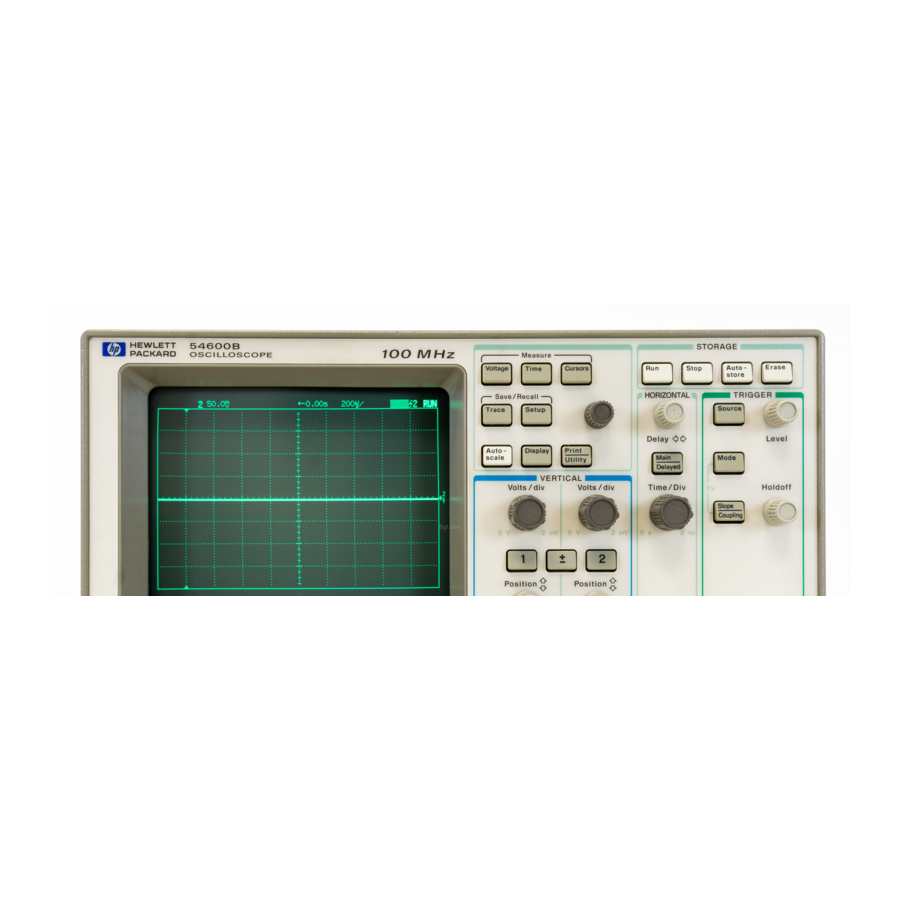
- Page 14 The Oscilloscope at a Glance Figure 1-1 is a diagram of the front-panel controls and input connectors of the HP 54600B and HP 54603B. Figure 1-2 is a diagram of the front-panel controls and input connectors of the HP 54601B and HP 54602B.
- Page 15 Figure 1–2 Storage keys General controls Horizontal controls Trigger controls Channel controls Channel inputs HP 54601B and HP 54602B Front Panel Controls Figure 1–3 Channel 4 is on, 10 V/div Delayed sweep is on, 500 ns/div Main sweep 500 s/div Autostore is on Auto triggered, positive Channel 3 is off...
- Page 16 Figure 1–4 Press this key To obtain this menu Press this key To obtain this menu Softkey Menu Reference 1–5...
-
Page 17: To Inspect The Instrument
The Oscilloscope at a Glance To inspect the instrument To inspect the instrument Inspect the shipping container for damage. Keep a damaged shipping container or cushioning material until the contents of the shipment have been checked for completeness and the instrument has been checked mechanically and electrically. -
Page 18: To Connect A Signal To The Oscilloscope
To connect a signal to the oscilloscope To connect a signal to the oscilloscope The HP 54600B and HP 54603B are a two-channel oscilloscopes with an external trigger input, while the HP 54601B and HP 54602B are four-channel oscilloscopes. The four-channel oscilloscope replaces the external trigger input with channels 3 and 4. - Page 19 The Oscilloscope at a Glance To connect a signal to the oscilloscope You should compensate 10:1 probes to match their characteristics to the oscilloscope. A poorly compensated probe can introduce measurement errors. To compensate a probe, follow these steps. Connect the 10:1 probe from channel 1 to the front-panel probe adjust signal on the oscilloscope.
-
Page 20: To Display A Signal Automatically
The trigger source selected is the highest numbered input that has a signal applied. (If a signal is connected to the external trigger input on the HP 54600B and HP 54603B, then it is selected as the trigger source.) Connect a signal to the oscilloscope. -
Page 21: To Set Up The Vertical Window
The Oscilloscope at a Glance To set up the vertical window To set up the vertical window The following exercise guides you through the vertical keys, knobs, and status line. Center the signal on the display with the Position knob. The Position knob moves the signal vertically, and it is calibrated. - Page 22 The Oscilloscope at a Glance To set up the vertical window Change the vertical setup and notice that each change affects the status line differently. You can quickly determine the vertical setup from the status line in the display. Change the vertical sensitivity with the Volts/Div knob and notice that it causes the status line to change.
-
Page 23: To Set Up The Time Base
The Oscilloscope at a Glance To set up the time base To set up the time base The following exercise guides you through the time base keys, knobs, and status line. Turn the Time/Div knob and notice the change it makes to the status line. - Page 24 The Oscilloscope at a Glance To set up the time base Turn the Delay knob and notice that its value is displayed in the status line. The Delay knob moves the main sweep horizontally, and it pauses at 0.00 s, mimicking a mechanical detent. At the top of the graticule is a solid triangle ( ) symbol and an open triangle ) symbol.
-
Page 25: To Trigger The Oscilloscope
Turn the trigger Level knob and notice the changes it makes to the display. On the HP 54601B and HP 54602B and on an internally triggered HP 54600B and HP 54603B, as you turn the Level knob or press a trigger menu key, for a short time two things happen on the display. - Page 26 Toggle each of the softkeys and notice which keys affect the status line. On the HP 54600B and HP 54603B, external trigger is always dc coupled. If you select ac coupling or low frequency reject, these functions do not occur until you change the trigger source to channel 1, channel 2, or line.
-
Page 27: To Use Roll Mode
The Oscilloscope at a Glance To use roll mode To use roll mode Roll mode continuously moves data across the display from right to left. It allows you to see dynamic changes (like adjusting a potentiometer) on low frequency signals. Two frequently used applications are transducer monitoring and power supply testing. -
Page 28: Operating Your Oscilloscope
Operating Your Oscilloscope... - Page 29 Operating Your Oscilloscope By now you are familiar with the , and VERTICAL, HORIZONTAL TRIGGER groups of the front-panel keys. You should also know how to determine the setup of the oscilloscope by looking at the status line. If you are unfamiliar with this information, we recommend you read chapter 1, "The Oscilloscope at a Glance."...
-
Page 30: To Use Delayed Sweep
Operating Your Oscilloscope To use delayed sweep To use delayed sweep Delayed sweep is a magnified portion of the main sweep. You can use delayed sweep to locate and horizontally expand part of the main sweep for a more detailed (high resolution) analysis of signals. The following steps show you how to use delayed sweep. - Page 31 Operating Your Oscilloscope To use delayed sweep Since both the main and delayed sweeps are displayed, there are half as many vertical divisions so the vertical scaling is doubled. Notice the changes in the status line. To display the delay time of the delayed sweep, either press or turn the delay knob.
- Page 32 Operating Your Oscilloscope To use delayed sweep Figure 2-2 shows the time reference set to center. Notice that the markers expand around the area of interest. You can place the markers over the area of interest with the delay knob, then expand the delayed sweep with the time base knob to increase the resolution.
-
Page 33: To Use Storage Oscilloscope Operation
Operating Your Oscilloscope To use storage oscilloscope operation To use storage oscilloscope operation There are four front-panel storage keys. They are white instant action keys that change the operating mode of the oscilloscope. The following steps demonstrate how to use these storage keys. Connect a signal to the oscilloscope and obtain a stable display. - Page 34 Operating Your Oscilloscope To use storage oscilloscope operation Using the position knob, move the trace up and down about one division. Notice that the last acquired waveform is in full bright and the previously acquired waveforms are displayed in half bright. To characterize the waveforms, use the cursors.
-
Page 35: To Capture A Single Event
Operating Your Oscilloscope To capture a single event To capture a single event To capture a single event, you need some previous knowledge of the signal in order to set up the trigger level and slope. For example, if the event is derived from TTL logic, a trigger level of 2 volts should work on a rising edge. - Page 36 There are twice as many sample points per waveform on the one-channel acquisition than on the two-channel acquisition. On the HP 54600B and HP 54603B, channels 1 and 2 are captured simultaneously. On the HP 54601B and HP 54602B channels 1 and 2 are captured simultaneously, then on the next trigger channels 3 and 4 are captured simultaneously.
-
Page 37: To Capture Glitches Or Narrow Pulses
Operating Your Oscilloscope To capture glitches or narrow pulses To capture glitches or narrow pulses A glitch is a rapid change in the waveform that is usually narrow as compared to the waveform. This oscilloscope has two modes of operation that you can use for glitch capture: peak detect and Autostore. - Page 38 Operating Your Oscilloscope To capture glitches or narrow pulses Characterize the glitch with delayed sweep. Peak detect functions in the main sweep only, not in the delayed sweep. To characterize the glitch with delayed sweep follow these steps. . Next press the Delayed softkey. Press Main/Delayed To obtain a better resolution of the glitch, expand the time base.
-
Page 39: To Trigger On A Complex Waveform
Operating Your Oscilloscope To trigger on a complex waveform To trigger on a complex waveform The difficulty in viewing a complex waveform is triggering on the signal. Figure 2-3 shows a complex waveform that is not synchronized with the trigger. The simplest trigger method is to trigger the oscilloscope on a sync pulse that is associated with the waveform. - Page 40 Operating Your Oscilloscope To trigger on a complex waveform Figure 2–3 Stable trigger, but the waveform is not synchronized with the trigger Figure 2–4 Holdoff synchronizes the waveform with the trigger In figure 2-4, the holdoff is set to about 25 s (the duration of the pattern.) 2–13...
-
Page 41: To Make Frequency Measurements Automatically
Operating Your Oscilloscope To make frequency measurements automatically To make frequency measurements automatically The automatic measurement capability of the oscilloscope makes frequency measurements easy, as the following steps demonstrate. Connect a signal to the oscilloscope and obtain a stable display. Press Time A softkey menu appears with six softkey choices. - Page 42 Operating Your Oscilloscope To make frequency measurements automatically If the Show Meas softkey is turned on, cursors are displayed on the waveform that show the measurement points for the right-most measurement result. If you select more than one measurement, you can show a previous measurement by reselecting the measurement.
-
Page 43: To Make Time Measurements Automatically
Operating Your Oscilloscope To make time measurements automatically To make time measurements automatically You can measure the following time parameters with the oscilloscope: frequency, period, duty cycle, width, rise time, and fall time. The following exercise guides you through the Time keys by making a rise time measurement. - Page 44 Operating Your Oscilloscope To make time measurements automatically Press Time A softkey menu appears with six softkey choices. Three of the softkeys are time measurement functions. Source Selects a channel for the time measurement. Time Measurements Three time measurement choices are available: Freq (frequency), Period, and Duty Cy (duty cycle).
- Page 45 Operating Your Oscilloscope To make time measurements automatically Time Measurements Four additional time measurement choices are available; Width, Width, Rise time, and Fall time. Width measurements are made at the 50% levels, whereas rise time and fall time measurements are made at the 10% to 90% levels.
-
Page 46: To Make Voltage Measurements Automatically
Operating Your Oscilloscope To make voltage measurements automatically To make voltage measurements automatically You can measure the following voltage parameters automatically with the oscilloscope: peak-to-peak, average, rms, maximum, minimum, top, and base. The following exercise guides you through the Voltage keys by making an rms voltage measurement. - Page 47 Operating Your Oscilloscope To make voltage measurements automatically Connect a signal to the oscilloscope and obtain a stable display. Press Voltage A softkey menu appears with six softkey choices. Three of the softkeys are voltage measurement functions. Source Selects a channel for the voltage measurement. Voltage Measurements Three voltage measurement choices are available: , and V .
- Page 48 Operating Your Oscilloscope To make voltage measurements automatically Figure 2–10 Delayed sweep isolates an area of interest for an rms voltage measurement Press the Next Menu softkey. Another voltage measurement softkey menu appears with six additional choices. Four of the softkeys are voltage measurement functions. Show Meas (show measurement) Displays the horizontal and vertical cursors that show where the measurement was taken on the signal.
-
Page 49: To Make Cursor Measurements
Operating Your Oscilloscope To make cursor measurements To make cursor measurements The following steps guide you through the front-panel key. Cursors You can use the cursors to make custom voltage or time measurements on the signal. Examples of custom measurements include rise time measurements from reference levels other than 10-90%, frequency and width measurements from levels other than 50%, channel-to-channel delay measurements, and voltage measurements. - Page 50 Operating Your Oscilloscope To make cursor measurements Figure 2–11 Cursors used to measure pulse width at levels other then the 50% points Figure 2–12 Cursors used to measure the frequency of the ringing on a pulse 2–23...
- Page 51 Operating Your Oscilloscope To make cursor measurements Figure 2–13 Cursors used to make channel-to-channel delay measurements Figure 2–14 The cursors track delayed sweep. Expand the display with delayed sweep, then characterize the event of interest with the cursors. 2–24...
- Page 52 Operating Your Oscilloscope To make cursor measurements Figure 2–15 Pressing t1 and t2 softkeys simultaneously causes the cursors to move together when the cursor knob is adjusted. Figure 2–16 By moving the cursors together, you can check for pulse width variations in a pulse train, as figures 2-15 and 2-16 show.
-
Page 53: To View Asynchronous Noise On A Signal
Operating Your Oscilloscope To view asynchronous noise on a signal To view asynchronous noise on a signal The following exercise shows how to use the oscilloscope to view asynchronous noise on a signal that is not synchronous to the period of the waveform. - Page 54 Operating Your Oscilloscope To view asynchronous noise on a signal Press Autostore Notice that STORE is displayed in the status line. Set the trigger mode to normal, then adjust the trigger level into the noise region of the signal. Decrease the sweep speed for better resolution of the asynchronous noise.
-
Page 55: To Reduce The Random Noise On A Signal
Operating Your Oscilloscope To reduce the random noise on a signal To reduce the random noise on a signal If the signal you are applying to the oscilloscope is noisy (figure 2-21), you can set up the oscilloscope to reduce the noise on the waveform (figure 2-22). - Page 56 Operating Your Oscilloscope To reduce the random noise on a signal Low frequency reject (LF reject) adds a high pass filter with the 3-dB point at 50 kHz (see figure 2-20). Use LF reject to remove low frequency signals such as power line noise from the trigger path. Figure 2–20 0 dB 3 dB down point...
- Page 57 Operating Your Oscilloscope To reduce the random noise on a signal Use averaging to reduce noise on the displayed waveform. To use averaging follow these steps. Press , the press the Average softkey. Display Notice that Av appears in the status line. Toggle the # Average softkey to select the number of averages that best eliminates the noise from the displayed waveform.
-
Page 58: To Save Or Recall Traces
Operating Your Oscilloscope To save or recall traces To save or recall traces The oscilloscope has two pixel memories for storing waveforms. The following exercise guides you through how to store and recall waveforms from pixel memories. Connect a signal to the oscilloscope and obtain a stable display. Press Trace A softkey menu appears with five softkey selections. -
Page 59: To Save Or Recall Front-Panel Setups
Operating Your Oscilloscope To save or recall front-panel setups The automatic measurement functions do not operate on stored traces. Remember, the stored waveforms are pictorial information rather than stored data. If you have not changed the oscilloscope setup, use the cursors to make the measurements. -
Page 60: To Reset The Instrument Setup
Operating Your Oscilloscope To reset the instrument setup To reset the instrument setup To reset the instrument to the default factory-preset configuration, press Setup Press the Default Setup softkey. To reset the instrument to the configuration that was present before pressing Autoscale, press the Undo Autoscale softkey. -
Page 61: To Use The Xy Display Mode
Operating Your Oscilloscope To use the XY display mode To use the XY display mode The XY display mode converts the oscilloscope from a volts versus time display to a volts versus volts display. You can use various transducers so the display could show strain versus displacement, flow versus pressure, volts versus current, or voltage versus frequency. - Page 62 X-axis input, channel 2 is the Y-axis input, and channel 4 (external trigger in the HP 54600B and HP 54603B) is the Z-axis input. If you only want to see portions of the Y versus X display, use the Z-axis input. Z-axis turns on and off the trace (analog oscilloscopes called this Z-blanking because it turned the beam on and off).
- Page 63 Operating Your Oscilloscope To use the XY display mode Move the Y1 and Y2 cursors to the center of the signal. Again, note the Y value. Figure 2–25 Y cursors centered Calculate the phase difference using formula below. second Y 111.9 27.25 degrees of phase shift.
- Page 64 Operating Your Oscilloscope To use the XY display mode Figure 2–26 Signals are 90° out of phase Figure 2–27 Signals are in phase 2–37...
-
Page 65: To Analyze Video Waveforms
Operating Your Oscilloscope To analyze video waveforms To analyze video waveforms Enhanced TV/Video Trigger (HP 54602B only) This section discusses basic TV video triggering. If you have Option 005 Enhanced TV/Video Trigger installed in your HP 54602B oscilloscope, refer to Chapter 3 "Using Option 005 Enhanced TV/Video Trigger."... - Page 66 Operating Your Oscilloscope To analyze video waveforms Set the time base to 200 s/div, then center the signal on the display with the delay knob (delay about 800 s). Press , then press the softkey. Delayed Main/Delayed Set the delayed sweep to 20 s/div, then set the expanded portion over the VITS (delay about 988.8 s).
- Page 67 Full screen display of the IRE Delay in TV line units hint HP 54600B-series oscilloscopes with system ROM versions 2.1 and greater have the ability to display delay in TV-line units. Using the TV field trigger mode activates this line-counting feature. When Field 1 or Field 2 is selected as the trigger source, delay can be set in terms of time or line number.
- Page 68 To analyze video waveforms Both-fields triggering hint The HP 54600B-series oscilloscopes can trigger on the vertical sync pulse in both TV fields at the same time. This allows you to view noninterlaced video signals which are common in today’s computer monitors. To trigger on both sync pulses, press Field 1 and Field 2 at the same time.
- Page 69 2–42...
-
Page 70: Using Option 005 Enhanced Tv/Video Trigger (Hp 54602B)
Using Option 005 Enhanced TV/Video Trigger (HP 54602B) - Page 71 Using Option 005 Enhanced TV/Video Trigger Basic TV/video triggering This section discusses Enhanced TV/Video triggering. If you do not have Option 005 installed in your oscilloscope, refer to the last section in Chapter 2 "To analyze video waveforms" for basic TV triggering procedures. You can use the Option 005 Enhanced TV/Video trigger with your HP 54602B oscilloscope.
- Page 72 Using Option 005 Enhanced TV/Video Trigger (HP 54602B) Option 005 gives you an Enhanced TV/Video Trigger for the oscilloscope, allowing highly detailed analysis of TV waveforms. This option offers: NTSC, PAL, PAL-M, SECAM and generic video formats Video autoscale IRE graticule and IRE cursor readout Full bandwidth rear panel output Trigger output Windowed FFT measurements (with Measurement/Storage module)
-
Page 73: To Select Tv Display Grid
Using Option 005 Enhanced TV/Video Trigger (HP 54602B) To select TV display grid To select TV display grid Press , then press the softkey until is selected. Grid Display To autoscale on a video signal Use a cable to connect a TV signal to channel 1. Press in the section of the front panel, and... -
Page 74: To Trigger On A Specific Line Of Video
Using Option 005 Enhanced TV/Video Trigger (HP 54602B) To trigger on a specific line of video To trigger on a specific line of video TV triggering requires greater than 1/4 division of sync amplitude, either channel 1 or channel 2 as the trigger source. Turning the trigger level knob in TV trigger does not change the trigger level because the trigger level is automatically set to the sync pulse tips. - Page 75 Using Option 005 Enhanced TV/Video Trigger (HP 54602B) To trigger on a specific line of video Figure 3-1 Triggering on Line 71 Table 3-1 Line Numbers per Field for Each TV Standard TV Standard Field 1 Field 2 Alt Fld NTSC 1 to 263 1 to 262...
-
Page 76: To Trigger On All Tv Line Sync Pulses
Using Option 005 Enhanced TV/Video Trigger (HP 54602B) To trigger on all TV line sync pulses To trigger on all TV line sync pulses To quickly find maximum video levels, you could trigger on all TV line sync pulses. When All Lines is selected as the TV trigger mode, the oscilloscope will trigger on the first line that it finds when the acquisition starts. -
Page 77: To Trigger On A Specific Field Of The Video Signal
Using Option 005 Enhanced TV/Video Trigger (HP 54602B) To trigger on a specific field of the video signal To trigger on a specific field of the video signal To examine the components of a video signal, trigger on either Field 1 or Field 2. -
Page 78: To Trigger On All Fields Of The Video Signal
Using Option 005 Enhanced TV/Video Trigger (HP 54602B) To trigger on all fields of the video signal To trigger on all fields of the video signal To quickly and easily view transitions between fields, or to find the amplitude differences between the fields, use the All Fields trigger. The oscilloscope will trigger on the first field it finds at the start of acquisition. -
Page 79: To Trigger On Odd Or Even Fields
Using Option 005 Enhanced TV/Video Trigger (HP 54602B) To trigger on odd or even fields To trigger on odd or even fields To check the envelope of your video signals, or to measure worst case distortion, trigger on the odd or even fields. When Field 1 is selected, the oscilloscope triggers on color fields 1 or 3. - Page 80 Using Option 005 Enhanced TV/Video Trigger (HP 54602B) To trigger on odd or even fields If a more detailed analysis is required, then only one color field should be selected to be the trigger. You can do this by using the oscilloscope’s holdoff control.
-
Page 81: To Make Cursor Measurements
Using Option 005 Enhanced TV/Video Trigger (HP 54602B) To make cursor measurements To make cursor measurements The following steps guide you through the front-panel Cursors key. You can use the cursors to make custom voltage or time measurements on the signal. Examples of custom measurements include rise time measurements from reference levels other than 10-90%, frequency and width measurements from levels other than 50%, channel-to-channel delay measurements, and voltage... - Page 82 Using Option 005 Enhanced TV/Video Trigger (HP 54602B) To make cursor measurements Figure 3-7 Color Sync measured with the cursors as 40 IRE 3–13...
-
Page 83: To Use Delayed Sweep
Using Option 005 Enhanced TV/Video Trigger (HP 54602B) To use delayed sweep To use delayed sweep Delayed sweep is a magnified portion of the main sweep. You can use delayed sweep to locate and horizontally expand part of the main sweep for a more detailed (high resolution) analysis of signals, for example multi-burst frequencies. - Page 84 Using Option 005 Enhanced TV/Video Trigger (HP 54602B) To use delayed sweep Figure 3-8 Modulated staircase or 5-step, measuring sync pulse fall time with delayed sweep Figure 3-9 Windowed frequency measurement in a multi-burst by use of delayed sweep 3–15...
-
Page 85: To Analyze Video Waveforms With Option 005
Using Option 005 Enhanced TV/Video Trigger (HP 54602B) To analyze video waveforms with Option 005 To analyze video waveforms with Option 005 The combination of the TV trigger, delayed sweep, and automatic measurements allow this oscilloscope to precisely analyze video waveforms. There is no need for external clamping to obtain a stable trigger when you are viewing unclamped video signals. - Page 86 Using Option 005 Enhanced TV/Video Trigger (HP 54602B) To analyze video waveforms with Option 005 Set the time base to 200 s/div, then center the signal on the display with the delay knob (delay about 800 s). Press , then press the softkey.
-
Page 87: To Window In On Harmonic Distortion Using Fft
Using Option 005 Enhanced TV/Video Trigger (HP 54602B) To window in on harmonic distortion using FFT To window in on harmonic distortion using FFT Sine waves that are not perfectly shaped in the time domain generate harmonics in the frequency domain. Viewing this distortion in the time domain is usually very difficult, unless the waveform is severely distorted. - Page 88 Using Option 005 Enhanced TV/Video Trigger (HP 54602B) To window in on harmonic distortion using FFT The FFT function then shows the harmonic content of the subcarrier in the figure below. Had the time/division and delays controls not been used to zoom in on the desired subcarrier, the entire video signal (with many frequency components) would have appeared in the frequency domain display.
-
Page 89: To Connect To Other Instruments
Using Option 005 Enhanced TV/Video Trigger (HP 54602B) To connect to other instruments To connect to other instruments The rear panel outputs provide an easy way to connect your Option 005-equipped oscilloscope to other instruments such as spectrum analyzers or frequency counters. To use a frequency counter: Connect the vertical output of the oscilloscope to the counter’s input. -
Page 90: Service
Verifying Oscilloscope Performance 4–5 Adjusting the Oscilloscope 4–27 Troubleshooting the Oscilloscope 4–40 Replacing Parts in the Oscilloscope 4–49 Service... - Page 91 Service If the oscilloscope is under warranty, you must return it to Hewlett-Packard for all service work covered by the warranty. See "To return the oscilloscope to Hewlett-Packard," on page 4–4. If the warranty period has expired, you can still return the oscilloscope to Hewlett-Packard for all service work.
- Page 92 Digital multimeter 0.1 mV resolution, better than 0.01% HP 34401A P, A, T accuracy Oscilloscope 100 MHz HP 54600B or equivalent Power supply 14 mV to 35 Vdc, 0.1 mV resolution HP 6114A Probe 10:1 division ratio HP 10432A Pulse generator Rise time <...
-
Page 93: To Return The Oscilloscope To Hewlett-Packard
Service To return the oscilloscope to Hewlett-Packard To return the oscilloscope to Hewlett-Packard Before shipping the oscilloscope to Hewlett-Packard, contact your nearest Hewlett-Packard Sales Office for additional details. Write the following information on a tag and attach it to the oscilloscope. -
Page 94: Verifying Oscilloscope Performance
Verifying Oscilloscope Performance This section shows you how to verify the electrical performance of the oscilloscope, using the performance characteristics in chapter 5 as the standard. The characteristics checked are dc calibrator, voltage measurement accuracy, bandwidth, horizontal accuracy, and trigger sensitivity. -
Page 95: To Check The Output Of The Dc Calibrator
Service Verifying Oscilloscope Performance To check the output of the DC CALIBRATOR In this test you measure the output of the with a multimeter. DC CALIBRATOR is used for self-calibration of the oscilloscope. The DC CALIBRATOR accuracy is not specified, but it must be within the test limits to provide for accurate self-calibration. -
Page 96: To Verify Voltage Measurement Accuracy
Test limits 1.9% of full scale (HP 54600B, HP 54601B, HP 54602B) 2.4% of full scale (HP 54603B) Table 4-3 Equipment Required... - Page 97 Service Verifying Oscilloscope Performance Set up the oscilloscope. , then press the Default Setup softkey. Press Setup , then press the V avg softkey. Press Voltage Set the Volts/Div to the first line of table 4-4. Adjust the channel 1 Position knob to place the baseline near (but not at) the bottom of the display.
- Page 98 — * Full scale is defined as 80 mV for the 5 mV/div and 2 mV/div ranges on HP 54600B, HP 54601B, HP 54603B. ** 1 mV/div range only on HP 54602B. Full scale is defined as 16 mV .
-
Page 99: To Verify Bandwidth
If you need a more exact procedure for checking bandwidth see, "To verify the bandwidth (alternate method)" on page 4–12. Test limits HP 54600B and HP 54601B, all channels ( 3 dB) dc to 100 MHz ac coupled 10 Hz to 100 MHz. - Page 100 Adjust the output of the signal generator for exactly 8 divisions of vertical deflection. Change the frequency of the signal generator to the value shown below for your instrument. Table 4-6 Signal Generator Frequency Setting Selected HP 54600B HP 54601B HP 54602B * HP 54603B Channel Channel 1 100 MHz...
-
Page 101: To Verify Bandwidth (Alternate Method)
You use the peak-to-peak voltage at 1 MHz and the upper bandwidth limit to calculate the bandwidth response of the oscilloscope. Test limits HP 54600B and HP 54601B, all channels ( 3 dB) dc to 100 MHz ac coupled 10 Hz to 100 MHz. HP 54602B Channels 1 &... - Page 102 Service Verifying Oscilloscope Performance Connect the equipment. Connect the signal generator to the input of the power splitter. Connect the power sensor to one output of the power splitter, and connect channel 1 of the oscilloscope to the other power splitter output (put the 50 feedthrough at the input of the oscilloscope).
- Page 103 0 dB reference. Change the frequency of the signal generator to the value shown below for your instrument. Table 4-8 Signal Generator Frequency Setting Selected HP 54600B HP 54601B HP 54602B * HP 54603B Channel Channel 1...
- Page 104 Service Verifying Oscilloscope Performance Change the time base to 5 ns/div. Wait a few seconds for the measurement to settle (averaging is complete), then note the Vp-p reading from the bottom of the display. Vp-p = ______ mV. Calculate the response using the following formula. step 8 result 20 log step 4 result...
-
Page 105: To Verify Horizontal T And 1/ T Accuracy
Service Verifying Oscilloscope Performance To verify horizontal t and 1/ t accuracy In this test you verify the horizontal t and 1/ t accuracy by measuring the output of a time mark generator with the oscilloscope. Test limits 0.01% 0.2% of full scale 200 ps. Table 4-9 Equipment Required Equipment... - Page 106 If the measurements are not within the test limits, see "Troubleshooting the Oscilloscope," on page 4–40. Change the time mark generator to 10 ns, and change the time base to HP 54600B, HP 54601B, 5 ns/div. Adjust the trigger level to obtain a stable display.
-
Page 107: To Verify Trigger Sensitivity
60 MHz, 1 div or 10 mV p-p External trigger HP 54600B and HP 54603B only dc to 25 MHz, 50 mV p-p dc to 100 MHz, 100 mV p-p (HP 54600B) dc to 60 MHz, 100 mV p-p (HP 54603B) 4–18... - Page 108 Critical specifications Recommended Model/Part Signal generator sine waves: Tek SG 503/Tek TM 501 25 MHz and 100 MHz–HP 54600B/HP 54601B 25 MHz and 250 MHz–HP 54602B 25 MHz and 60 MHz–HP 54603B Power splitter Outputs differ <0.15 dB HP 11667B...
- Page 109 If adjusting the trigger does not help, see "Troubleshooting the Oscilloscope," on page 4–40. Repeat steps 1 through 4 for channel 2 on the HP 54600B and HP 54603B (channels 2 to 4 on the HP 54601B and HP 54602B).
- Page 110 Service Verifying Oscilloscope Performance Verify the external trigger sensitivity at 100 MHz (60 MHz for External Trig HP 54603B) and 100 mV p-p (HP 54600B and HP 54603B only). Sensitivity , then press the Ext softkey. Press Source Use the power splitter to connect the signal generator to the channel 1 input and to the external trigger input.
-
Page 111: To Verify Vertical Output On Option 005
Service Verifying Oscilloscope Performance To verify Vertical Output on Option 005 This section applies only to Option 005 Enhanced TV/Video Trigger if installed on the HP 54602B. In this test we will use the oscilloscope’s channel 2 to measure the amplitude of the Vertical Output ( connector on rear panel) signal. - Page 112 HP 54600B Performance Test Record Date_______________________________________ Serial No. ______________________________________ Test by_____________________________________ Test Interval ____________________________________ Work Order No._______________________________ Recommended Next Testing _______________________ Temperature _________________________________ Output of dc calibrator Limits Result 4.990 V to 5.010 V __________ Voltage measurement accuracy Range Reading...
- Page 113 HP 54601B Performance Test Record Date_______________________________________ Serial No. ______________________________________ Test by_____________________________________ Test Interval ____________________________________ Work Order No._______________________________ Recommended Next Testing _______________________ Temperature _________________________________ Output of dc calibrator Limits Result 4.990 V to 5.010 V __________ Voltage measurement accuracy Range Reading Test Limits Channel 1 Channel 2...
- Page 114 HP 54602B Performance Test Record Date_______________________________________ Serial No. ______________________________________ Test by_____________________________________ Test Interval ____________________________________ Work Order No._______________________________ Recommended Next Testing _______________________ Temperature _________________________________ Output of dc calibrator Limits Result 4.990 V to 5.010 V __________ Voltage measurement accuracy Range Reading Test Limits Channel 1 Channel 2...
- Page 115 HP 54603B Performance Test Record Date_______________________________________ Serial No. ______________________________________ Test by_____________________________________ Test Interval ____________________________________ Work Order No._______________________________ Recommended Next Testing _______________________ Temperature _________________________________ Output of dc calibrator Limits Result 4.990 V to 5.010 V _________ Voltage measurement accuracy Range Reading Test Limits Channel 1 Channel 2...
-
Page 116: Adjusting The Oscilloscope
Adjusting the Oscilloscope This section explains how to adjust the oscilloscope so that it is at optimum operating performance. You should perform the hardware adjustments periodically as indicated below. Hardware at 12 months or 2,000 hours of operation Firmware at 6 months or 1000 hours of operation, or if ambient temperature is greater than 10 C from the calibration temperature, or if the user desires to maximize the measurement accuracy... -
Page 117: To Adjust The Power Supply
Service Adjusting the Oscilloscope To adjust the power supply On the power supply there is only one adjustment and that is for the 5.1 V. The other voltages are based on the 5.1 V adjustment. In this procedure you use a multimeter to measure the 5.1 V, and if necessary, you adjust the supply to within tolerance. - Page 118 Service Adjusting the Oscilloscope Measure the power supply voltages at L1, L2, and L3 on the system board. The test points are not marked on the system board; see figure below for location of test points. Make sure that the voltage measurements are within the following tolerances. Table 4-13 Power Supply Voltage Tolerances 5.1 V...
- Page 119 Service Adjusting the Oscilloscope If the 5.1 V measurement is out of tolerance, adjust the 5.1 V adjustment on the power supply. The 15.75 V supplies are not adjustable and are dependent upon the 5.1 V supply. If adjusting the power supply does not bring all the voltages within tolerance, see "Troubleshooting the Oscilloscope,"...
-
Page 120: To Perform The Self-Calibration
Service Adjusting the Oscilloscope To perform the self-calibration In this procedure you load the default calibration factors to give a known starting point for the firmware calibration. However, once the default calibration factors are loaded, you must perform the remainder of the firmware calibration to maintain the accuracy of the oscilloscope. - Page 121 CALIBRATOR output first to channel 3, then to channel 1, then to channel 4, and finally to channel 2. (Channels 1 and 2 only on the HP 54600B and HP 54603B.) After the message "Press Continue to return to calibration appears on the display, press the softkey.
-
Page 122: To Adjust The Low-Frequency Compensation
Service Adjusting the Oscilloscope To adjust the low-frequency compensation In this procedure you adjust the low-frequency compensation adjustment for each channel. Table 4-15 Equipment Required Equipment Critical specifications Recommended Model/Part Square wave generator 30 kHz at about 3 Vp-p HP 8112A Feedthrough 50 , BNC (m) and (f) HP10100C... - Page 123 Service Adjusting the Oscilloscope Adjust the channel 1 low-frequency compensation adjustment for as flat a pulse top as possible. Repeat steps 4 through 9 for channel 2 (channels 2 to 4 on the HP 54601B and HP 54602B). Figure 4–3 Low-frequency pulse response adjustments Low-frequency compensation adjustment locations...
-
Page 124: To Adjust The High-Frequency Pulse Response
Service Adjusting the Oscilloscope To adjust the high-frequency pulse response In this procedure you adjust the high-frequency pulse response for each channel. Table 4-16 Equipment Required Equipment Critical specifications Recommended Model/Part Pulse generator Rise time < 875 ps PSPL 1107B TD and PSPL 1110B Driver Adapter SMA (f) to BNC (m) - Page 125 Service Adjusting the Oscilloscope Adjust the channel 1 high-frequency response for 1.5 minor division of overshoot (6%). Repeat steps 4 through 9 for channel 2 (channels 2 to 4 on the HP 54601B and HP 54602B). Figure 4–4 High-frequency pulse response adjustments High-frequency pulse response adjustment locations 4–36...
-
Page 126: To Adjust The Display
Service Adjusting the Oscilloscope To adjust the display When to adjust the display The display adjustments are optional and normally do not require adjustment. You should use this procedure only for the few cases when the display is obviously out of adjustment. Table 4-16 Equipment Required Equipment... - Page 127 Service Adjusting the Oscilloscope Adjust HB Cont (half bright contrast) for the best contrast between the half bright and full bright blocks. You can readjust Sub Bri, intensity control, and HB Cont to suit your individual preference. Press any key to continue to the next test pattern. Then, adjust H.Hold (horizontal hold) to center the display horizontally.
-
Page 128: To Adjust The Option 005 Offset (R15)
Service Adjusting the Oscilloscope To adjust the Option 005 offset (R15) (HP 54602B only) The oscilloscope must be calibrated before performing this adjustment. Refer to "To perform the self-calibration" on page 4–31. Table 4-17 Equipment Required Equipment Required Critical Specification Recommended Model/Part Digital Multimeter... -
Page 129: Troubleshooting The Oscilloscope
Recommended model/part Digital multimeter Accuracy 0.05%, 1 mV resolution HP 34401A Oscilloscope 100 MHz HP 54600B Probe 10:1 division ratio HP 10432A Dummy load Compatible with power supply see note 1 below See page 4–41 to construct your own dummy load. -
Page 130: To Construct Your Own Dummy Load
Service Troubleshooting the Oscilloscope To construct your own dummy load Obtain a connector compatible with the connector on the Low Voltage Power Supply. Connect the following load resistors to the connector. 5.1 V requires a 3 A load, 1.7 and 15 W on pin 15, 17, or 19. 15.75 V requires a 1.3 A load, 12.2 and 20.5 W on pin 11 or 13. -
Page 131: To Check Out The Oscilloscope
Service Troubleshooting the Oscilloscope To check out the oscilloscope Is there an interface module connected to the oscilloscope? If yes, do the following steps. If not, go to step 2. Turn off the oscilloscope. Remove the module. Turn on the oscilloscope, then check for the failing symptom. If the failing symptom disappears, replace the module. - Page 132 Service Troubleshooting the Oscilloscope Disconnect the display cable, then check the following signals on the system board. Table 4-18 Signals at U56 Signal Frequency Pulse width Voltage U16 Pin 7 19.72 kHz 38.0 s 2.6 Vp-p U16 Pin 24 Hsync 19.72 kHz 3.0 s 5.0 Vp-p...
- Page 133 Service Troubleshooting the Oscilloscope Is the fan running? If yes, go to "To run the internal self-tests," on page 4–46. If not, do the steps below. The Low Voltage Power Supply has a thermal cut-out circuit. If the fan is defective, the Low Voltage Power Supply shuts down when it gets too hot for safe operation.
-
Page 134: To Check The Low Voltage Power Supply
Service Troubleshooting the Oscilloscope To check the Low Voltage Power Supply Disconnect the power cord, then set the oscilloscope on its side. Connect the negative lead of the multimeter to a ground point on the oscilloscope. Connect the power cord and turn on the oscilloscope. Measure the power supply voltages at L1, L2, and L3 on the system board. -
Page 135: To Run The Internal Self-Tests
Service Troubleshooting the Oscilloscope To run the internal self-tests Perform the keyboard test. Press Print/Utility Press the Self Tst softkey, then press the Keyboard softkey. A pictorial diagram of the front panel will appear on the display. Press each key, and notice that when you press a key a corresponding block on the display fills in. - Page 136 Service Troubleshooting the Oscilloscope Perform the test. Press the RAM softkey. Does the display message say Test Passed? If yes, press any key to continue. If not, (the display message says Test Failed) replace the system board. Perform the display test. Press Print/Utility Press the Self Tst softkey, then press the Display softkey.
-
Page 137: To Troubleshoot Option 005
Service Troubleshooting the Oscilloscope To troubleshoot Option 005 (HP 54602B only) To isolate a malfunction to the Option 005 board, do the following: Disconnect the three cables that connect the Option 005 board to the system board. Verify proper oscilloscope operation, as described in this chapter. If the oscilloscope passes the performance verification and the malfunction still occurs when the Option 005 board is reconnected, then you should replace the Option 005 board. -
Page 138: Replacing Parts In The Oscilloscope
Replacing Parts in the Oscilloscope This section contains instructions for removing and ordering replaceable assemblies. Also in this section is a parts list for the assemblies and hardware of the oscilloscope that you can order from Hewlett-Packard. Before working on the oscilloscope, read the safety summary at the back of this book. -
Page 139: To Replace An Assembly
Service Replacing Parts in the Oscilloscope To replace an assembly Refer to the exploded view of the oscilloscope, figure 4–11 (figure 4–12 for Option 005 board), for details on how the oscilloscope fits together. To install an assembly, follow the instructions in reverse order. You will need the following tools to disassemble the oscilloscope: T15 TORX driver to remove the oscilloscope from the cabinet and to remove the fan. -
Page 140: To Remove The Fan
Service Replacing Parts in the Oscilloscope To remove the fan Disconnect the fan cable from the power supply board. Using the T15 TORX driver, remove the three screws that hold the fan to the deck. To remove the front panel Remove the intensity knob by pulling straight out. - Page 141 Service Replacing Parts in the Oscilloscope When installing the front panel, make sure that the power switch shaft is aligned with its mating hole in the front panel. The front panel swings in to engage the two retainer tabs. Before attempting to engage the retainer tabs, make sure that the six hooks on top of the front panel are fully engaged with their mating holes in the sheet metal.
-
Page 142: To Remove The Display
Service Replacing Parts in the Oscilloscope To remove the display Remove the front panel. Disconnect the ribbon cable and the calibration cable from the display. Using the T10 TORX driver, remove the two screws that hold the display to the deck. Make sure that when you reinstall these screws that you use the correct parts. -
Page 143: Power Supply
Service Replacing Parts in the Oscilloscope Power supply Remove the fan. Disconnect the ground wire (green wire with the yellow stripe) from the deck. Disconnect the ribbon cable from the power supply board. Use a screw driver to gently unhook the latch that holds the white shaft to the power switch, then disconnect the shaft from the power switch. -
Page 144: Keyboard
Service Replacing Parts in the Oscilloscope Keyboard Remove the front panel. Remove all the knobs by pulling straight out. Flex the bezel of the front panel to unsnap the small keyboard under the display opening. Using the T10 TORX driver, remove the three screws from the large keyboard. -
Page 145: To Remove The Handle
Service Replacing Parts in the Oscilloscope To remove the handle Rotate the handle down until it is just past the last detent position (about 1/2 inch before the handle touches the bottom of the oscilloscope), then pull the sides of the handle out of the cabinet. To remove the Option 005 board Remove the oscilloscope from the cabinet. -
Page 146: To Order A Replacement Part
Service Replacing Parts in the Oscilloscope To order a replacement part The system board is part of an exchange program with Hewlett-Packard. The exchange program allows you to exchange a faulty assembly with one that has been repaired and performance verified by Hewlett-Packard. After you receive the exchange assembly, return the defective assembly to Hewlett-Packard. - Page 147 Service Replacing Parts in the Oscilloscope To order a part in the material list, quote the Hewlett-Packard part number, indicate the quantity desired, and address the order to your nearest Hewlett-Packard Sales Office. To order a part not listed in the material list, include the model number and serial number of the oscilloscope, a description of the part (including its function), and the number of parts required.
- Page 148 Service Replacing Parts in the Oscilloscope Figure 4–11 Exploded view of oscilloscope 4–59...
- Page 149 2190-0068 Lock washer 1251-2485 Connector dust cover 1400-1581 Cable clamp 54600-41901 Large keypad (HP 54600B and HP 54603B only) 54601-41901 Large keypad (HP 54601B and HP 54602B only) 54600-94306 Front-panel label (HP 54600B only) 54601-94306 Front-panel label (HP 54601B only)
- Page 150 Front-panel cover Attenuator covers replacement parts (these are a part of the A3 system board) 54601-04101 Channel attenuator cover (one used on HP 54600B and HP 54603B, two used on HP 54601B and HP 54602B) 0515-0667 M3 x 25 machine screw that holds attenuator cover to...
- Page 151 Service Replacing Parts in the Oscilloscope Figure 4-12 Exploded view of Option 005 and related oscilloscope parts 4–62...
- Page 152 Service Replacing Parts in the Oscilloscope Table 4-21 Option 005 Replaceable Parts Reference HP Part Qty Description Designator Number System Board (part of standard instrument) 54602-66502 Video Trigger Board 0515-0380 Machine screw M4 X 10 (part of standard instrument) 0515-0430 Machine screw M3 X 6 (+2 screws for Option 005) 54601-00101 Deck (part of standard instrument)
- Page 153 4–64...
-
Page 154: Performance Characteristics
Performance Characteristics... - Page 155 Performance Characteristics The performance characteristics describe the typical performance of the oscilloscope. You will notice that some of the characteristics are marked as tested, these are values that you can verify with the performance tests under "Verifying Oscilloscope Performance," on page 4–5.
-
Page 156: Vertical System
60 MHz 3 dB ac coupled, 10 Hz to 60 MHz Rise time 3.5 ns (calculated, HP 54600B & HP 54601B) <2.33 ns (calculated, channels 1 & 2, HP 54602B) <1.4 ns (calculated, channels 3 & 4, HP 54602B) 5.8 ns (calculated, HP 54603B) - Page 157 Vertical System Channels 1 and 2 Range 2 mV/div to 5 V/div (lower limit is 1 mV/div for the HP 54602B) Accuracy 1.9% (HP 54600B, HP 54601B, and HP 54602B) 2.4% (HP 54603B) Verniers Fully calibrated, accuracy about 3.5% 1, 2, 3 Cursor accuracy Single cursor accuracy vertical accuracy 1.2% of full scale 0.5% of...
-
Page 158: Horizontal System
Performance Characteristics Horizontal System Horizontal System Sweep speeds 5 s/div to 2 ns/div main and delayed (HP 54600B, HP 54601B, HP 54602B 5 s/div to 5 ns/div main and delayed (HP 54603B) Accuracy 0.01% 0.2% of full scale 200 ps Vernier Accuracy 0.05%... -
Page 159: Trigger System
1 div or 10 mV Sources Channels 1, 2, 3, 4, and line on HP 54601B & HP 54602B Channels 1, 2, line, and external on HP 54600B and HP 54603B Coupling ac, dc, LF reject, HF reject, and noise reject... - Page 160 Performance Characteristics Trigger System External trigger (HP 54600B and HP 54603B only) Range 18 V Sensitivity HP 54600B dc to 25 MHz 50 mV dc to 100 MHz 100 mV HP 54603B dc to 25 MHz 50 mV dc to 60 MHz...
-
Page 161: Xy Operation
Performance Characteristics XY Operation XY Operation Z Blanking TTL high blanks trace Bandwidths X and Y same as vertical system Phase difference 3 degrees at 100 kHz Display System Display 7-inch raster CRT Resolution 255 vertical by 500 horizontal points Controls Front-panel intensity control Graticule 8 10 grid or frame... -
Page 162: Acquisition System
Performance Characteristics Acquisition System Acquisition System Maximum sample rate 20 MSa/s Resolution 8 bits Simultaneous channels Channels 1 and 2 or channels 3 and 4 Record length Vectors off 4,000 points Vectors on and/or single shot 2,000 points Maximum update rate Vectors off 1,500,000 points/sec Vectors on 60 full screens/sec, independent of the number of waveforms being displayed... -
Page 163: Advanced Functions
50 Hz, duty cycle >1%, and voltage level channels 1 and 2 >20 mVp-p, channels 3 and 4 >100 mVp-p, external trigger (HP 54600B and HP 54603B only) >100 mVp-p. Save/Recall 16 front-panel setups Trace memory Two volatile pixel memories... -
Page 164: General
Performance Characteristics General General Environmental The instrument meets or exceeds the environmental requirements of characteristics MIL-T-28800D for Type III, Class 3, Style D equipment as described below. Ambient temperature (Tested to MIL-T-28800D paragraphs 4.5.5.13 option 2 and 4.5.5.14) Operating –10 C to +55 C Nonoperating –51 C to +71 C Humidity (tested to Hewlett-Packard environmental specification section 758 paragraphs 4.0, 4.1, and 4.2 for class B-1 products) - Page 165 Performance Characteristics General RE01 Parts 5 and 6 measured at 30.5 cm, 15 dB relaxation to 20 kHz, and exceptioned from 20 kHz to 50 kHz. RE02 Part 2 (limited to 1 GHz) Full limits of class A1c and A1f, with option 002 installed without option 002 installed 10 dB relaxation, 14 kHz to 1 GHz RS02 Part 2, Part I Exceptioned RS02 Part 2, Part II Exceptioned...
-
Page 166: Option 005 General Performance Characteristics (Hp 54602B Only)
Performance Characteristics Option 005 General Performance Characteristics (HP 54602B only) Option 005 General Performance Characteristics (HP 54602B only) Video Standards NTSC PAL-M SECAM Generic Video Trigger Modes Line (number) of Field 1 Field 2 Alternate Fields All Lines Field 1 Defined as that field with the 3 lines of vertical sync starting at line 4. -
Page 167: Option 005 Trigger System
Performance Characteristics Option 005 Trigger System (HP 54602B only) Option 005 Trigger System (HP 54602B only) Internal trigger Sensitivity Performance remains unchanged Coupling Performance remains unchanged Modes Performance remains unchanged Holdoff Performance remains unchanged TV triggering Available on channels 1 and 2 only TV line and field 0.5 division of composite sync for stable display External trigger Performance remains unchanged... -
Page 168: Glossary
Glossary This glossary is organized into BW Lim (Bandwidth Limit) Limits two parts: oscilloscope and the displayed bandwidth of the se- TV/video trigger terms. The lected channel to 20 MHz, and is TV/video trigger terms apply to the available for channels 1 and 2 only. HP 54602B with Option 005 This feature is useful for viewing installed. - Page 169 Glossary External Trigger Is available only Line In TV trigger mode, the oscil- on the two channel oscilloscope. loscope triggers on the TV line sync Nonviewable input that is usable as a pulses. As a trigger source, the oscil- trigger source only. loscope triggers off of the power line frequency.
- Page 170 Glossary Print/Utility Allows access to the Single (single shot) The oscillo- module menus and service menus. scope triggers once when the trigger conditions are met. The oscilloscope Probe Allows selection of 1, 10, or must be rearmed before the oscillo- 100 to match a probe’s division ratio scope retriggers by pressing either so that the vertical scaling and volt-...
- Page 171 Glossary TV/Video Trigger Terms Trace Allows access to the trace storage keys. Blanking Level The level of the Trace Mem (trace memory) One composite picture signal that of two pixel memory locations used separates the range containing for storing traces. picture information from the range containing synchronizing information.
- Page 172 Glossary Composite Video For color, this Field 2 Triggers on the field 2 por- consists of blanking, field, and line tion of the video signal. synchronizing signals, color synchro- nizing signals, plus chrominance and Frame One complete picture luminance picture information. consisting of two fields of interlaced These are all combined to form the scanning lines.
- Page 173 Glossary Line In TV trigger mode, the oscil- PAL Phase Alternating Line or loscope triggers on the TV line sync Phase Alteration Line rate. Color pulses. As a trigger source, the oscil- television standards used in Europe. loscope triggers off of the power line A 625 line, 50 Hz field system.
- Page 174 Glossary Vertical Blanking Interval The blanking portion at the beginning of each field. It contains the equalizing pulses, the vertical sync pulses, and VITS (if desired). Presently 18 to 21 lines in duration. Vertical Interval Reference (VIR) A signal used as a reference for am- plitude and phase characteristics of a color television program (FCC as- signed to line 19).
- Page 175 Glossary–8...
-
Page 176: Index
Index ac coupling, 1–10, 1–14, 5–4, 5–6 calibration DAC softkey, 4–6 accuracy adjustments, 4–27 to 4–39 DC Calibrator, 4–6, 4–31 cursors, 5–4 to 5–5 delay, 4–32 dc coupling, 1–10, 1–14, 5–4, 5–6 horizontal, 5–5 self, 4–31 to 4–32 DC level shifts, 3–16 vertical, 5–4 vertical, 4–32 default setup, 2–33... - Page 177 Index horizontal maximum input voltage fall time, 2–16, 2–18 accuracy, 5–5 trigger, 5–7 Fast Fourier Transform (FFT), 3–18 to characteristics, 5–5 vertical, 5–3 3–19 hold, 4–38 measurement Field 1, 3–8 vernier, 1–12 automatic, 2–16 to 2–21, 3–14 Field 1 softkey, 2–38 humidity characteristics, 5–11 clear, 2–17 Field 2, 3–8...
- Page 178 Index Previous Menu softkey, 2–18 setup saving, 2–32 odd field, 3–10 to 3–11 Print Show Meas softkey, 2–15, 2–17 offset See User’s Guide for optional interface signal adjusting option 005, 4–39 module automatic display, 1–9 one-channel acquisition, 2–9 probe dc component, 1–10 Option 005, 3–2 attenuation factor, 1–7 noise, 2–26, 2–30...
- Page 179 Index time base video autoscale, 3–12 accuracy, 5–5 display grid, 3–4 VITS, 2–38 preset configuration, 2–33 grid, 3–12 voltage range, 1–12, 5–5 trigger, 1–14, 2–38, 2–41, 3–16 adjustment, 4–28 setup, 1–12 to 1–13 trigger mode, 2–38 maximum input, 1–7, 5–3 time cursor, 3–12 trigger-both fields, 2–41 measurement accuracy, 4–7...
-
Page 180: Declaration Of Conformity
Colorado Springs, CO 80907 USA declares, that the product Product Name: Digitizing Oscilloscope Model Number(s): HP 54600B, HP 54601B, HP 54602B, and HP 54603B Product Option(s): conforms to the following Product Specifications: Safety: IEC 1010-1:1990+A1 / EN 61010-1:1993 UL 3111 CSA-C22.2 No. - Page 181 Product Regulations IEC 1010-1:1990+A1 / EN 61010-1:1993 Safety UL 3111 CSA-C22.2 No.1010.1:1993 This Product meets the requirement of the European Communities (EC) EMC Directive 89/336/EEC. Emissions EN55011/CISPR 11 (ISM, Group 1, Class A equipment) Immunity EN50082-1 Code Notes IEC 555-2 IEC 555-3 IEC 801-2 (ESD) 4kV CD, 8kV AD IEC 801-3 (Rad.) 3 V/m...
- Page 182 © Copyright Hewlett- Safety Safety Symbols Service instructions are for Packard Company ,1992, 1997 trained service personnel. To This apparatus has been avoid dangerous electric All Rights Reserved. designed and tested in shock, do not perform any accordance with IEC Instruction manual symbol: service unless qualified to do Publication 1010, Safety...
- Page 183 Product Warranty No other warranty is About this edition expressed or implied. This Hewlett-Packard This is the HP 54600B, Hewlett-Packard product has a warranty HP54601B, HP 54602B, and specifically disclaims the against defects in material HP 54603B Oscilloscopes implied warranties of and workmanship for a period User and Service Guide.