Siemens SIMATIC Rack PC 840 V2 Operating Instructions Manual
Hide thumbs
Also See for SIMATIC Rack PC 840 V2:
- Getting started (42 pages) ,
- Getting started (42 pages)

Related Manuals for Siemens SIMATIC Rack PC 840 V2


Summary of Contents for Siemens SIMATIC Rack PC 840 V2
- Page 1 Operating Instructions Edition 05/2006 SIMATIC Industrial PC SIMATIC Rack PC 840 V2 Industrial PC Rack PC 840 V2 simatic DOCUMENTATION DOCUMENTATION...
- Page 3 Introduction Safety information Description SIMATIC Application Planning Industrial PC Installation SIMATIC Rack PC 840 V2 Connecting Operating Instructions Commissioning Integration Functions Expansions and configuration Maintenance and service Alarm, error and system messages Troubleshooting Technical data Dimensional Drawings Detailed descriptions Appendix...
-
Page 4: Edition
Trademarks All names identified by ® are registered trademarks of the Siemens AG. The remaining trademarks in this publication may be trademarks whose use by third parties for their own purposes could violate the rights of the owner. -
Page 5: Table Of Contents
Removable hard disks ....................... 7-4 7.3.3.1 Change the PATA hard disk ...................... 7-4 7.3.3.2 Change the SATA hard disk ...................... 7-4 7.3.4 RAID system ..........................7-5 7.3.5 SCSI System..........................7-6 SIMATIC Rack PC 840 V2 Operating Instructions, Edition 05/2006, A5E00248055-04... - Page 6 Installing the SCSI Controller software .................. 11-27 11.2.9 Installing burner/DVD software ....................11-27 Alarm, error and system messages ...................... 12-1 12.1 Boot error messages........................ 12-1 12.2 BIOS POST codes ........................12-3 SIMATIC Rack PC 840 V2 Operating Instructions, Edition 05/2006, A5E00248055-04...
- Page 7 16.5.6 Security menu ........................16-38 16.5.7 Power menu ........................... 16-40 16.5.8 Boot menu..........................16-41 16.5.9 Version menu ......................... 16-43 16.5.10 Exit menu ..........................16-44 16.5.11 Default BIOS Setup entries....................16-45 SIMATIC Rack PC 840 V2 Operating Instructions, Edition 05/2006, A5E00248055-04...
- Page 8 Certificates and Approvals ....................... 17-2 17.3 Service and support ......................... 17-4 17.4 Retrofitting instructions......................17-6 ESD Guidelines ............................ 18-1 18.1 ESD Guidelines........................18-1 Abbreviations............................19-1 Glossary ............................. Glossary-1 Index..............................Index-1 SIMATIC Rack PC 840 V2 Operating Instructions, Edition 05/2006, A5E00248055-04...
-
Page 9: Introduction
Scope of this documentation This documentation applies to all supplied variants of the SIMATIC Rack PC 840 V2 and describes the delivery status as of May 2006. Classification in the information landscape The operating instructions are available on the supplied "Documentation and Drivers"... -
Page 10: Guideline To The Operating Instructions
Structure, function and features of the vital components, allocation of system resources and use of the BIOS Setup Appendix Guidelines and certifications, service and support, notes on retrofitting ESD Guidelines General ESD guidelines. SIMATIC Rack PC 840 V2 Operating Instructions, Edition 05/2006, A5E00248055-04... -
Page 11: Safety Information
Contact your technical support team or where you purchased your PC to find out which system expansion devices may safely be installed. Caution If you install or exchange system expansions and damage your device, the warranty becomes void. SIMATIC Rack PC 840 V2 Operating Instructions, Edition 05/2006, A5E00248055-04... - Page 12 • Always pull the mains connector and disconnect the battery before you install or remove modules which are sensitive to ESD. • Handle modules fitted with ESDs by their edges only. • Do not touch any wiring posts or conductors on modules containing ESDs. SIMATIC Rack PC 840 V2 Operating Instructions, Edition 05/2006, A5E00248055-04...
-
Page 13: Description
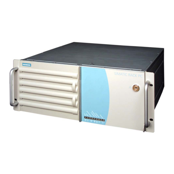
Description Overview SIMATIC Rack PC 840 V2 is an industrial PC in 19" rack format (4HU) with excellent industrial functionality. • High expandability • Rugged • High product continuity Figure 3-1 Rack PC 840 V2 SIMATIC Rack PC 840 V2... -
Page 14: Areas Of Application
Description 3.2 Areas of application Areas of application SIMATIC Rack PC 840 V2 offers a high-performance and highly flexible 19" rack PC platform to machine, plant and control cabinet engineering for use in a machine-oriented industrial environment: • Measuring, control and closed loop control of process and machine data, for example, ultrasonic measurement technology in the automotive industry, gear test benches •... -
Page 15: Function
-up to 1280x1024 at 100 Hz / 32-bit color resolution -up to 1600 x1200 at 60 Hz / 16-bit color resolution Interfaces PROFIBUS/MPI (12 Mbps) 12 Mbps (isolated potential, compatible to CP 5611); optional SIMATIC Rack PC 840 V2 Operating Instructions, Edition 05/2006, A5E00248055-04... - Page 16 DDR266 SDRAM (PC2100) 3 slots, up to 2 GB Hard disk Floppy drive 1,44 MB, installation in front drive bay Hard disk drives 40 GB EIDE, 3.5" Operating system without SIMATIC Rack PC 840 V2 Operating Instructions, Edition 05/2006, A5E00248055-04...
- Page 17 Dual Layer 12x CD-ROM/CD-R Read 48x CD-RW Read 40x DAE Read 40x Write: DVD+R 16x DVD+RW 8x DVD-R 16x DVD-RW 6x DVD+R9 (DL) 8x DVD-R DL 8x CD-R 48x CD-RW 32x SIMATIC Rack PC 840 V2 Operating Instructions, Edition 05/2006, A5E00248055-04...
- Page 18 Watchdog • Temperature • Fan speed • Hard disk monitoring (SMART) • System / Ethernet monitoring (Heart Beat) • SIMATIC PC Software tool for saving data locally Image Creator SW SIMATIC Rack PC 840 V2 Operating Instructions, Edition 05/2006, A5E00248055-04...
-
Page 19: Design
Fan / power supply unit Power supply connection Rating plate (may also be mounted on the inside of the front panel door) Drive cooling fan at the rear (optional) Connecting elements Expansion slots SIMATIC Rack PC 840 V2 Operating Instructions, Edition 05/2006, A5E00248055-04... -
Page 20: Operator Controls
For switching the device on or off Caution Data may be lost when the PC performs a hardware reset. Warning The on/off button signal does not switch off power to the PC! SIMATIC Rack PC 840 V2 Operating Instructions, Edition 05/2006, A5E00248055-04... -
Page 21: Connecting Elements
Position of the IEC power connector Description IEC power connector for the AC power supply to the device. The allowable supply voltage is 120 V AC or 230 V AC SIMATIC Rack PC 840 V2 Operating Instructions, Edition 05/2006, A5E00248055-04... -
Page 22: Status Displays
HARDDISK Display for hard disk access - No access GREEN - Access POWER PC status display - Disconnected from mains YELLOW - Standby (hibernate) GREEN - PC in operation SIMATIC Rack PC 840 V2 3-10 Operating Instructions, Edition 05/2006, A5E00248055-04... -
Page 23: Application Planning
• Check the delivery unit for any visible transport damage. • Verify that the shipment contains the complete unit and your separately ordered accessories. Please inform your local dealer of any disagreements or transport damages. SIMATIC Rack PC 840 V2 Operating Instructions, Edition 05/2006, A5E00248055-04... - Page 24 You may need the Product Key in case you reinstall the operating system. Figure 4-2 COA label Serial number S VP ... Order No. 6ES ... Microsoft Windows Product Key Ethernet address SIMATIC Rack PC 840 V2 Operating Instructions, Edition 05/2006, A5E00248055-04...
-
Page 25: Ambient And Environmental Conditions
If these requirements are not adhered to when installing the system, the approvals according to UL 60950-1, EN 60950-1 are voided and there will is a danger of overheating and a hazard for personnel! SIMATIC Rack PC 840 V2 Operating Instructions, Edition 05/2006, A5E00248055-04... - Page 26 Application Planning 4.3 Ambient and environmental conditions SIMATIC Rack PC 840 V2 Operating Instructions, Edition 05/2006, A5E00248055-04...
-
Page 27: Installation
The mounting screws of the telescopic rails may not protrude more than 5 mm into the enclosure. Caution Danger of bodily harm! It is not permitted to mount the device only on the 19" brackets of the front panel. SIMATIC Rack PC 840 V2 Operating Instructions, Edition 05/2006, A5E00248055-04... - Page 28 Remove the bonded stands when mounting the device on telescopic rails. Restricted technical specifications for drives in the front drive bay apply for this type of installation. For details, refer to the technical data or retrofitting instructions. SIMATIC Rack PC 840 V2 Operating Instructions, Edition 05/2006, A5E00248055-04...
-
Page 29: Connecting
Caution I/O devices not capable of hot-plugging may only be connected after the device has been disconnected from the power supply. Caution Strictly adhere to the specifications for I/O modules. SIMATIC Rack PC 840 V2 Operating Instructions, Edition 05/2006, A5E00248055-04... -
Page 30: Connecting The Device To Power
Always ensure free and easy access to the power inlet on the device or that the safety power outlet of the building installation is freely accessible and located close to the device. SIMATIC Rack PC 840 V2 Operating Instructions, Edition 05/2006, A5E00248055-04... - Page 31 Connect the power cord to the mains outlet and switch on the mains isolation switch (if this exists). The yellow power LED (standby) on the front panel of the PC lights up. SIMATIC Rack PC 840 V2 Operating Instructions, Edition 05/2006, A5E00248055-04...
-
Page 32: Equipotential Bonding
PC is to be installed. The minimum conductor cross-section may not be less than 5 mm SIMATIC Rack PC 840 V2 Operating Instructions, Edition 05/2006, A5E00248055-04... -
Page 33: Commissioning
Notice The PC may not be switched off when you run setup. Do not change the default BIOS settings, otherwise the operating system setup may become corrupted. 4. Automatic restart SIMATIC Rack PC 840 V2 Operating Instructions, Edition 05/2006, A5E00248055-04... -
Page 34: Notes On Operation
The written data can only be verified by comparing these with the source. To be on the safe side, data should be verified after every burning session. SIMATIC Rack PC 840 V2 Operating Instructions, Edition 05/2006, A5E00248055-04... -
Page 35: Dvd Burner
The written data can only be verified by comparing these with the source. To be on the safe side, data should be verified after every burning session. SIMATIC Rack PC 840 V2 Operating Instructions, Edition 05/2006, A5E00248055-04... -
Page 36: Removable Hard Disks
2. Follow the cable in the computer in order to get to the right swap frame. 3. Set the key switch into the vertical position (Off position). 4. Push up the bezel of the hard disk cartridge. 5. Remove the hard disk cartridge. SIMATIC Rack PC 840 V2 Operating Instructions, Edition 05/2006, A5E00248055-04... -
Page 37: Raid System
It may take several hours to synchronize a new disk in the background, depending on the size of the hard disk and on the system load. The redundant system state RAID 1 is reached again only after synchronization is completed. SIMATIC Rack PC 840 V2 Operating Instructions, Edition 05/2006, A5E00248055-04... -
Page 38: Scsi System
The SCSI controller is installed on slot 5 of the bus module. Note Information about the operation of the SCSI system can be found in the SCSI user manual on the included SIMATIC PC – Documentation and Drivers CD. SIMATIC Rack PC 840 V2 Operating Instructions, Edition 05/2006, A5E00248055-04... -
Page 39: Integration
To couple the device to an S7 PLC, you need the software package “SOFTNET for PROFIBUS”. Further information For further information, refer to the catalog and to the online ordering system of Siemens A&D. Internet address: http://www.mall.automation.siemens.com SIMATIC Rack PC 840 V2... - Page 40 Integration 8.1 Integration SIMATIC Rack PC 840 V2 Operating Instructions, Edition 05/2006, A5E00248055-04...
-
Page 41: Functions
The temperature error is retained until the temperatures have fallen below the thresholds and are reset by one of the following measures: • Acknowledgement of the error message by means of the SOM program • Restart of the device. SIMATIC Rack PC 840 V2 Operating Instructions, Edition 05/2006, A5E00248055-04... -
Page 42: Watchdog (Wd)
The flashing Temp LED indicates that the device is being operated at its limits. Please check whether the permissible ambient temperature has been exceeded, or whether the filter is soiled. SIMATIC Rack PC 840 V2 Operating Instructions, Edition 05/2006, A5E00248055-04... -
Page 43: Safecard On Motherboard (Som)
The description of the driver and SOM program are available on the CD "Documentation and Drivers" under Drivers & Updates\<device>\... From the CD, run Install.bat and follow the instructions on your screen. SIMATIC Rack PC 840 V2 Operating Instructions, Edition 05/2006, A5E00248055-04... - Page 44 Functions 9.5 Safecard on Motherboard (SOM) SIMATIC Rack PC 840 V2 Operating Instructions, Edition 05/2006, A5E00248055-04...
-
Page 45: Expansions And Configuration
(ESD) directives for handling components which are sensitive to electrostatic charge. Tools All mechanical installation tasks on the device can be carried out with TORX T8, Torx T10 and TORX T15 screwdrivers. Preparation Disconnect the device from mains. SIMATIC Rack PC 840 V2 10-1 Operating Instructions, Edition 05/2006, A5E00248055-04... - Page 46 (you can also remove the lid screw without using a tool.) Slide the lid back to the mechanical stop (approx. 1 cm) Lift up the lid and remove it SIMATIC Rack PC 840 V2 10-2 Operating Instructions, Edition 05/2006, A5E00248055-04...
-
Page 47: Memory Expansion
The electronic components on the PCBS are highly sensitive to electrostatic discharge. It is therefore vital to take precautionary measures when handling these components. Refer to the directives for handling components which are sensitive to electrostatic charge. SIMATIC Rack PC 840 V2 10-3 Operating Instructions, Edition 05/2006, A5E00248055-04... - Page 48 Display of the current memory configuration A new memory module is automatically detected. The allocation of the ”base memory and extended memory” is automatically displayed when you switch on the device.. SIMATIC Rack PC 840 V2 10-4 Operating Instructions, Edition 05/2006, A5E00248055-04...
-
Page 49: Installing Pci / At Format Pcbs
BIOS Setup. Information on the assignment of PCI IRQs to the PCI slots is found in the "Advanced Menu" or "Bus Board" section. PCI graphics modules with an expansion ROM of up to 48 kB can be used. SIMATIC Rack PC 840 V2 10-5 Operating Instructions, Edition 05/2006, A5E00248055-04... -
Page 50: Installing Disk Drives
In the rear disk drive bay Description Rear disk drive bay Two 3.5" mounting bays for hard disk drives (with shock and vibration damping) SIMATIC Rack PC 840 V2 10-6 Operating Instructions, Edition 05/2006, A5E00248055-04... -
Page 51: Installation And Removal Of Disk Drives In The Front Drive Bay
Slide the disk drive into the bay from the front Mount the disk drive into the drive bay using four screws Reinstall the drive bay Connect the power and data cables to the disk drive. SIMATIC Rack PC 840 V2 10-7 Operating Instructions, Edition 05/2006, A5E00248055-04... -
Page 52: Installation And Removal Of Disk Drives In The Rear Drive Bay
Remove the screw (2) in the interior of the enclosure Disconnect the power cable and the data cable from the installed disk drives Remove the drive bay from the cubicle SIMATIC Rack PC 840 V2 10-8 Operating Instructions, Edition 05/2006, A5E00248055-04... - Page 53 Slide the disk drive into the bay from the front Mount the disk drive into the drive bay using four screws Reinstall the drive bay Connect the power and data cables to the disk drive. SIMATIC Rack PC 840 V2 10-9 Operating Instructions, Edition 05/2006, A5E00248055-04...
- Page 54 Expansions and configuration 10.4 Installing disk drives SIMATIC Rack PC 840 V2 10-10 Operating Instructions, Edition 05/2006, A5E00248055-04...
-
Page 55: Maintenance And Service
Notice Note the ESB instructions. Limitation of Liability All technical data and licenses apply only to upgrades approved by SIEMENS. No liability can be accepted for impairment of functions caused by the use of third-party devices or components. Tools All mechanical installation tasks on the device can be carried out with Torx T10 and TORX T15 screwdrivers as well as a side-cutter. -
Page 56: Replacing The Backup Battery
1. Note down the current settings of the BIOS Setup. A list in which you can note down this information is found in the BIOS manual 2. Disconnect the device from mains and unplug all cables. SIMATIC Rack PC 840 V2 11-2 Operating Instructions, Edition 05/2006, A5E00248055-04... - Page 57 4. Close the device. Reconfiguring the BIOS Setup When a battery is exchanged, the configuration data of the device is lost and must be reentered in the BIOS setup. SIMATIC Rack PC 840 V2 11-3 Operating Instructions, Edition 05/2006, A5E00248055-04...
-
Page 58: Removing The Power Supply Module
Disconnect this power cable from the floppy disk drive. Remove the screws (1) on the steel bracket. SIMATIC Rack PC 840 V2 11-4 Operating Instructions, Edition 05/2006, A5E00248055-04... -
Page 59: Removing The Bus Board
3. Remove the three screws holding the bus board 4. Remove the one screw on the outside of the cubicle rear wall. 5. Remove the bus board from the motherboard. SIMATIC Rack PC 840 V2 11-5 Operating Instructions, Edition 05/2006, A5E00248055-04... -
Page 60: Removing The O
TORX) from the front panel of the device (1) 2. Remove the USB socket from the inside of the front panel 3. Disconnect connector X44 from the OP and remove the three screws SIMATIC Rack PC 840 V2 11-6 Operating Instructions, Edition 05/2006, A5E00248055-04... -
Page 61: Removing The Motherboard
4. Remove the four screws and three hexagonal bolts from the motherboard. Remove the eight hexagonal bolts at the interfaces. The motherboard is supplied as spare part without processor, memory modules and bus board. SIMATIC Rack PC 840 V2 11-7 Operating Instructions, Edition 05/2006, A5E00248055-04... -
Page 62: Removing The Equipment Fan Or Changing The Filter
2. Front panel remove and change filter if necessary (only filters of the same type are allowed to be used) 3. Loosen both knurled nuts of the fan bracket SIMATIC Rack PC 840 V2 11-8 Operating Instructions, Edition 05/2006, A5E00248055-04... - Page 63 How to remove the fan 4. Remove the fan bracket from the cubicle 5. Remove both fan connectors 6. Remove all fan screws and remove the fan from the bracket SIMATIC Rack PC 840 V2 11-9 Operating Instructions, Edition 05/2006, A5E00248055-04...
- Page 64 Ensure that the arrow on the fan points away from the fan bracket. Fan mounting position The figure shows the correct fan mounting position. Note the direction of the arrow! SIMATIC Rack PC 840 V2 11-10 Operating Instructions, Edition 05/2006, A5E00248055-04...
-
Page 65: Processor Replacement
2. Open the device. Removing the processor How to remove the processor 1. Disconnecting the processor fan connector 2. Unscrew the four screws on the processor heat sink and remove heat sink SIMATIC Rack PC 840 V2 11-11 Operating Instructions, Edition 05/2006, A5E00248055-04... - Page 66 11.1 Removing and installing hardware components How to remove the processor 4. Opening the processor latch 5. Removing the processor Installing the processor How to install the processor 1. Inserting the processor SIMATIC Rack PC 840 V2 11-12 Operating Instructions, Edition 05/2006, A5E00248055-04...
- Page 67 4. Fix the heat sink into position with the four screws: Screw the screws into position diagonally and tighten evenly, in order to avoid tilting. 5. Plug in the fan cable SIMATIC Rack PC 840 V2 11-13 Operating Instructions, Edition 05/2006, A5E00248055-04...
-
Page 68: Reinstalling The Software
When you select the "Restore entire hard disk" option, ALL the data, user settings and authorizations or license keys will be lost on the hard disk. SIMATIC Rack PC 840 V2 11-14 Operating Instructions, Edition 05/2006, A5E00248055-04... -
Page 69: Partitioning The Hard Disk
Factory setup of the hard disk with Windows 2000 and Windows XP: • One partition with a FAT32 file system • One partition with a NTFS file system To restore the partition to its factory state, proceed as follows: SIMATIC Rack PC 840 V2 11-15 Operating Instructions, Edition 05/2006, A5E00248055-04... - Page 70 6. To format the partition from the Recovery CD as described earlier in steps 1 to 3, restart the computer, the select A:\>Format C: (A: is the CD drive). to format . Caution All the data of the relevant partition will be lost during formatting. SIMATIC Rack PC 840 V2 11-16 Operating Instructions, Edition 05/2006, A5E00248055-04...
-
Page 71: Setting Up The Partitions Under Windows Nt
ESC key. After initialization, a boot menu selection screen is displayed. 2. Select CD-ROM drive 3. From the ”Microsoft Windows 98 Startup Menu” screen form, select 2. Boot for FDISK, FORMAT or Windows NT Setup SIMATIC Rack PC 840 V2 11-17 Operating Instructions, Edition 05/2006, A5E00248055-04... - Page 72 8. The formatting of the NTFS partitions is performed by the setup program of Windows NT. Run Windows NT Setup. Caution All the data of the relevant partition will be lost during formatting. SIMATIC Rack PC 840 V2 11-18 Operating Instructions, Edition 05/2006, A5E00248055-04...
-
Page 73: Installing Microsoft Windows Operating Systems
ESC key. After initialization, a boot menu selection screen is displayed. 3. Select CD-ROM drive 4. From the ”Microsoft Windows 98 Startup Menu” screen form, select 1. Boot for CD Recovery SIMATIC Rack PC 840 V2 11-19 Operating Instructions, Edition 05/2006, A5E00248055-04... - Page 74 "Windows NT Workstation Technical Reference, Version 4.0 (not included in the package). It contains specific information for system administrators who are responsible for installing, managing, and integrating Windows NT Workstation in a network or multiuser environment. SIMATIC Rack PC 840 V2 11-20 Operating Instructions, Edition 05/2006, A5E00248055-04...
-
Page 75: Installation From The Recovery Cd For Microsoft Windows 2000
ESC key. After initialization, a Boot Menu screen is displayed for selecting the boot device. 3. Select CD-ROM drive 4. From the ”Microsoft Windows 98 Startup Menu” screen form, select 1. Boot for CD Recovery SIMATIC Rack PC 840 V2 11-21 Operating Instructions, Edition 05/2006, A5E00248055-04... - Page 76 Language settings for the system field and the Keyboard layout field in the Input Locales tab. In addition to the menu and dialog language settings, you also need to set the default language by selecting Set Default... from the Regional Options dialog box. SIMATIC Rack PC 840 V2 11-22 Operating Instructions, Edition 05/2006, A5E00248055-04...
-
Page 77: Installation From The Recovery Cd For Microsoft Windows Xp
2. To boot from the CD, when the BIOS message appears press: <F2> to enter SETUP or <ESC> to display the boot menu the ESC key. After initialization, a Boot Menu screen is displayed for selecting the boot device. SIMATIC Rack PC 840 V2 11-23 Operating Instructions, Edition 05/2006, A5E00248055-04... - Page 78 8. Confirm the end message. 9. Run Windows Setup with <<DRIVE>>:\I386\Winnt.bat <<DRIVE>> is the destination drive to which the Recovery were copied. 10. Now follow the instructions on the screen. SIMATIC Rack PC 840 V2 11-24 Operating Instructions, Edition 05/2006, A5E00248055-04...
-
Page 79: Installing Drivers And Software
When you install Windows NT, you need to install the Windows NT Service Pack before you install any other drivers. The Service Pack must be reinstalled after a driver installation. SIMATIC Rack PC 840 V2 11-25 Operating Instructions, Edition 05/2006, A5E00248055-04... -
Page 80: Installing The Raid Controller Driver
To do so, change the start mode to restart in the Control Panel > Devices > ATAPI. Restart the computer. Notes on Windows 2000/XP When you install Windows 2000/XP, select FastTrak from the list. SIMATIC Rack PC 840 V2 11-26 Operating Instructions, Edition 05/2006, A5E00248055-04... -
Page 81: Installing The Scsi Controller Software
The driver is available in the directory \Drivers\SCSI\U160 on the included "Documentation and Drivers" CD. 11.2.9 Installing burner/DVD software The supplied CD provides information about installation of the burner/DVD software. SIMATIC Rack PC 840 V2 11-27 Operating Instructions, Edition 05/2006, A5E00248055-04... - Page 82 Maintenance and service 11.2 Reinstalling the software SIMATIC Rack PC 840 V2 11-28 Operating Instructions, Edition 05/2006, A5E00248055-04...
-
Page 83: Alarm, Error And System Messages
Check the SETUP settings. Contact your technical support team. Keyboard error Check whether the keyboard is properly connected. Key seizure Check whether a key on the keyboard has seized. SIMATIC Rack PC 840 V2 12-1 Operating Instructions, Edition 05/2006, A5E00248055-04... - Page 84 System time-out Hardware error. Contact your technical support team. Real-time clock error Clock chip error. Contact your technical support team. Keyboard controller error Keyboard error. Contact your technical support team. SIMATIC Rack PC 840 V2 12-2 Operating Instructions, Edition 05/2006, A5E00248055-04...
-
Page 85: Bios Post Codes
Setup or removing installed expansion modules from the bus module TP_PARITY Test of the memory Replace memory modules modules BIOS Power On Self Test completed. Loading operating system SIMATIC Rack PC 840 V2 12-3 Operating Instructions, Edition 05/2006, A5E00248055-04... - Page 86 This can occur following a BIOS update. • 2x short Error in checksum test of the BIOS: This can occur following a battery replacement or when the battery is empty. SIMATIC Rack PC 840 V2 12-4 Operating Instructions, Edition 05/2006, A5E00248055-04...
-
Page 87: Troubleshooting
2. Set the time and date in the setup menu. Although the BIOS The backup battery is In this case, please contact your technical support team. setting is OK, the time dead. and data are still wrong. SIMATIC Rack PC 840 V2 13-1 Operating Instructions, Edition 05/2006, A5E00248055-04... -
Page 88: Problems When Using Modules Of Third-Party Manufacturers
PC. If the error no longer occurs, the third- party module was the cause of the fault. Replace this Connector assignments deviate. • module with a Siemens module or contact the module “Reset Configuration” in BIOS • supplier. -
Page 89: Technical Data
± 2 kV; (to IEC 61000-4-5:1995; length > 30 m) Immunity to discharges of static electricity ± 6 kV contact discharge; (according to IEC 61000-4-2) ± 8 kV air discharge; (according to IEC 61000-4-2) SIMATIC Rack PC 840 V2 14-1 Operating Instructions, Edition 05/2006, A5E00248055-04... - Page 90 25 W Max. accumulated power dissipation of all Accumulated power of 80 W may not be exceeded. slots Chipset VIA P4N266 A max. 2 GB DDR266 SDRAM, unbuffered, no ECC SIMATIC Rack PC 840 V2 14-2 Operating Instructions, Edition 05/2006, A5E00248055-04...
- Page 91 DVD-RW/+RW 13x DVD-Video Single Layer 16x Dual Layer 12x CD-ROM/CD-R Read 48x CD-RW Read 40x DAE Read 40x Write: DVD+R 16x DVD+RW 8x DVD-R 16x DVD-RW 6x DVD+R9 (DL) 8x SIMATIC Rack PC 840 V2 14-3 Operating Instructions, Edition 05/2006, A5E00248055-04...
- Page 92 Restrictions for drives in the front drive bay: When operating with stands, the values of 30 m/s may not be exceeded. Devices mounted on telescopic rails may not be exposed to mechanical stress. SIMATIC Rack PC 840 V2 14-4 Operating Instructions, Edition 05/2006, A5E00248055-04...
-
Page 93: Power Requirements Of Components (Maximum Values)
Efficiency of the power supply approx. 65 % based on the selected device configuration The permitted max. accumulated power of the + 5 V and + 3.3 V supply is 180 W. SIMATIC Rack PC 840 V2 14-5 Operating Instructions, Edition 05/2006, A5E00248055-04... -
Page 94: Ac Voltage Supply
Technical data of the telescopic rails 14.4 Ultimate load per pair Minimum 30 kg Full extraction length Minimum 470 mm Rail thickness Maximum 9.7 mm Fixing screws M5 x 6 mm SIMATIC Rack PC 840 V2 14-6 Operating Instructions, Edition 05/2006, A5E00248055-04... -
Page 95: Dimensional Drawings
Dimensional Drawings 15.1 Dimensional Drawing of the Device 15.1 Figure 15-1 Dimension drawing SIMATIC Rack PC 840 V2 15-1 Operating Instructions, Edition 05/2006, A5E00248055-04... -
Page 96: Dimensional Drawing For The Use Of Telescopic Rails
15.2 Dimensional drawing for the use of telescopic rails 15.2 Dimensional drawing for the use of telescopic rails 15.2 Figure 15-2 Dimensional drawing for the use of telescopic rails SIMATIC Rack PC 840 V2 15-2 Operating Instructions, Edition 05/2006, A5E00248055-04... -
Page 97: Dimensional Drawings For The Installation Of Expansion Modules
15.3 Dimensional drawings for the installation of expansion modules 15.3 Dimensional drawings for the installation of expansion modules 15.3 Figure 15-3 AT module Figure 15-4 Long format PCI module SIMATIC Rack PC 840 V2 15-3 Operating Instructions, Edition 05/2006, A5E00248055-04... - Page 98 Dimensional Drawings 15.3 Dimensional drawings for the installation of expansion modules SIMATIC Rack PC 840 V2 15-4 Operating Instructions, Edition 05/2006, A5E00248055-04...
-
Page 99: Detailed Descriptions
Flash BIOS and the backup battery. Figure 16-1 Motherboard Processor with fan Slot for the bus board 3 slots for memory module Backup battery SIMATIC Rack PC 840 V2 16-1 Operating Instructions, Edition 05/2006, A5E00248055-04... -
Page 100: Technical Features Of The Motherboard
- 10/100 Mbps, potentially VT6103, VIA Rhine-Family) isolated Electrically isolated within the safety extra-low voltage circuit (SELV) Optional product feature Depends on the CPU type Depends on the selected device configuration SIMATIC Rack PC 840 V2 16-2 Operating Instructions, Edition 05/2006, A5E00248055-04... -
Page 101: Position Of The Ports On The Motherboard
• Ports for connecting external devices • Ports for internal components (drives, bus boards, etc.) The figure below shows the location of the internal and external ports on the motherboard. Figure 16-2 Motherboard interfaces SIMATIC Rack PC 840 V2 16-3 Operating Instructions, Edition 05/2006, A5E00248055-04... -
Page 102: External Interfaces
– 10–17 – n.c. – – – – – – – DTR (S1) Data terminal ready Output – – – RI (M3) Incoming call Input 23–25 – n.c. – SIMATIC Rack PC 840 V2 16-4 Operating Instructions, Edition 05/2006, A5E00248055-04... - Page 103 GND (E2) Functional ground (reference potential) – DSR (M1) Ready for operation Input RTS (S2) Request to send Output CTS (M2) Clear to send Input RI (M3) Incoming call Input SIMATIC Rack PC 840 V2 16-5 Operating Instructions, Edition 05/2006, A5E00248055-04...
- Page 104 Pin No. Abbreviations Meaning Input /Output Data channel, mouse Input/output – n.c. – Chassis ground – P5VFK + 5 V (fused) Output Clock channel, Input/output mouse – n.c. – SIMATIC Rack PC 840 V2 16-6 Operating Instructions, Edition 05/2006, A5E00248055-04...
- Page 105 Data channel Input /Output + Data Data channel Input /Output Chassis ground – The connectors are of type A. The ports are rated as high-current USB 2.0 (500 mA). SIMATIC Rack PC 840 V2 16-7 Operating Instructions, Edition 05/2006, A5E00248055-04...
- Page 106 Signal line A of MPI module Input/output RTS_PG RTS output signal of the MPI module. The control Output signal is "1" when the PG is sending. Shield on connector casing Optional product feature SIMATIC Rack PC 840 V2 16-8 Operating Instructions, Edition 05/2006, A5E00248055-04...
- Page 107 – resistor Received data Input 7, 8 SYMT Internal 75-Ohm terminating – resistor Shield – LED yellow Connection – LED green Activity – is not necessary for data transfer SIMATIC Rack PC 840 V2 16-9 Operating Instructions, Edition 05/2006, A5E00248055-04...
- Page 108 Output Chassis ground – – n.c. – DDC_DAT Display Data Channel Data Input/output EXT_H Horizontal synchronizing pulse Output EXT_V Vertical synchronizing pulse Output DDC_CLK Display Data Channel Clock Input/output SIMATIC Rack PC 840 V2 16-10 Operating Instructions, Edition 05/2006, A5E00248055-04...
-
Page 109: Internal Ports
OP connection Assignment for SCSI activity connector, X39 Type JST B2B-PH-SM3-TB Pin No. Abbreviations Meaning Input /Output SCSI HD_N 0-V level means that the SCSI port is active Input SIMATIC Rack PC 840 V2 16-11 Operating Instructions, Edition 05/2006, A5E00248055-04... - Page 110 Reserved Chassis ground – Reserved Chassis ground – – – Note For detailed information on the pin assignments of the interfaces, please contact Costumer Support or the Repair Center. SIMATIC Rack PC 840 V2 16-12 Operating Instructions, Edition 05/2006, A5E00248055-04...
-
Page 111: Bus Board
INT – D (B8) channel 4 channel 1 channel 2 channel 3 channel 4 channel 1 channel 2 Bold letters in the table means: Master interrupt of the slot module SIMATIC Rack PC 840 V2 16-13 Operating Instructions, Edition 05/2006, A5E00248055-04... -
Page 112: Exclusive Pci Hardware Interrupt
If a pre-assigned or reserved interrupt is assigned manually, it is indicated with a yellow star. This means it cannot be used. Interrupts not reserved by the system can be assigned twice. SIMATIC Rack PC 840 V2 16-14 Operating Instructions, Edition 05/2006, A5E00248055-04... -
Page 113: Pin Assignment Of The Bus Board Connectors
Input /Output Chassis ground + 12 V Power supply Output Note For detailed information on the pin assignments of the interfaces, please contact Costumer Support or the Repair Center. SIMATIC Rack PC 840 V2 16-15 Operating Instructions, Edition 05/2006, A5E00248055-04... -
Page 114: Operator Panel
It remains in this state until the short-circuit is cancelled. Note For detailed information on the pin assignments of the interfaces, please contact Costumer Support or the Repair Center. SIMATIC Rack PC 840 V2 16-16 Operating Instructions, Edition 05/2006, A5E00248055-04... -
Page 115: System Resources
0064 Keyboard controller 0067 006F Motherboard resources 0070 0075 System CMOS/real-time clock 0076 0080 Motherboard resources 0081 008F DMA controller 0090 009F Motherboard resources 00A0 00A1 Programmable interrupt controller SIMATIC Rack PC 840 V2 16-17 Operating Instructions, Edition 05/2006, A5E00248055-04... - Page 116 Dynamic area; resources are managed via Plug and Play 0400 0777 Unused 0778 077F ECP LPT 1 0780 0CF7 1400 unused 0CF8 0CFB PCI configuration index fixed SIMATIC Rack PC 840 V2 16-18 Operating Instructions, Edition 05/2006, A5E00248055-04...
-
Page 117: Interrupt Assignments
Priority interrupt for VGA 1) 2) IRQ11 Reserved for SOM or ISA modules IRQ12 PS/2 mouse IRQ13 Numeric processor fixed IRQ14 1. HD controller 1 (primary) IRQ15 2. HD controller 2 (secondary) SIMATIC Rack PC 840 V2 16-19 Operating Instructions, Edition 05/2006, A5E00248055-04... - Page 118 BIOS Setup menu. Refer to the respective ISA module documentation for the respective interrupt to be allocated. These functions can be disabled in the Setup This releases allocated resources. SIMATIC Rack PC 840 V2 16-20 Operating Instructions, Edition 05/2006, A5E00248055-04...
-
Page 119: Memory Address Assignments
16 MB Kbytes of top of memory are configuration reserved for USB. 7000 0000 FFF7 FFFF PCI memory address space For PCI expansion cards FFF8 0000 FFFF FFFF Firmware HUB SIMATIC Rack PC 840 V2 16-21 Operating Instructions, Edition 05/2006, A5E00248055-04... -
Page 120: Bios Setup
With the default setting of your PC, the display shown below appears following power-on, for example: Phoenix BIOS 4.0 Release 6.0 A5E000xxxxx-ES0x Copyright 1985-2002 Phoenix Technologies Ltd. All Rights Reserved. SIMATIC Rack PC 840 V2 Vxx.xx.xx CPU = Intel® Pentium®4 CPU 2.40 GHz 639K System RAM Passed 127MB Extended RAM Passed Mouse initialized Press <F2>... -
Page 121: Bios Setup Menus
BIOS. In this case you should select the default settings (F9) or eliminate the conflict. You can move between the menu forms using the cursor keys [←] left and [→] right. SIMATIC Rack PC 840 V2 16-23 Operating Instructions, Edition 05/2006, A5E00248055-04... -
Page 122: Main Menu
Information about the programming device (for example, release status) can be found here. Exit Used for terminating and saving. 16.5.4 Main menu Figure 16-5 SETUP main menu (example) (1) Selectable submenu SIMATIC Rack PC 840 V2 16-24 Operating Instructions, Edition 05/2006, A5E00248055-04... - Page 123 The type of floppy disk drive installed in the PC is set here. The following entries are possible: [Disabled] if no disk drive is available. [1.44 MB, 3 1/2"] Default setting for an installed disk drive A SIMATIC Rack PC 840 V2 16-25 Operating Instructions, Edition 05/2006, A5E00248055-04...
- Page 124 "LBA Mode capacities > 528 MB are supported. The value is dependant on the drive used and and Control" should only be set with the Type field set to "Auto". SIMATIC Rack PC 840 V2 16-26 Operating Instructions, Edition 05/2006, A5E00248055-04...
- Page 125 Write access is not concluded until the entry has been made in main memory [Write Back] Write access is concluded immediately, the entry in main memory takes place in the background (default) SIMATIC Rack PC 840 V2 16-27 Operating Instructions, Edition 05/2006, A5E00248055-04...
- Page 126 Summary screen The most important system parameters are displayed when the system boot phase completes. 'Enabled' means that the feature is active. 'Disabled' means that the feature is inactive. SIMATIC Rack PC 840 V2 16-28 Operating Instructions, Edition 05/2006, A5E00248055-04...
- Page 127 Key Click Creates an audible click when a key is pressed. Keyboard auto–repeat rate Increase in automatic key repeat rate Keyboard auto–repeat delay On-delay of automatic keyboard repeat SIMATIC Rack PC 840 V2 16-29 Operating Instructions, Edition 05/2006, A5E00248055-04...
- Page 128 The relevant driver and the application must be started for operation of the monitoring functions. Fan control [Enabled] The fan speed is controlled based on the temperature. [Disabled] The fan always runs at full speed. SIMATIC Rack PC 840 V2 16-30 Operating Instructions, Edition 05/2006, A5E00248055-04...
- Page 129 USB 5 on the front panel. [Disabled] The USB interfaces on port 0 to 5 support only USB 1.1 and occupy resources as described earlier. SIMATIC Rack PC 840 V2 16-31 Operating Instructions, Edition 05/2006, A5E00248055-04...
-
Page 130: Advanced Menu
No local IDE interface. Large disk [DOS] The drive tables are adapted for DOS access operations in access mode accordance with Enhanced IDE. [OTHER] The tables are not adapted. SIMATIC Rack PC 840 V2 16-32 Operating Instructions, Edition 05/2006, A5E00248055-04... - Page 131 The resources used by an interface are released when you disable the interface in question. The I/O addresses and interrupts are pre-assigned; it is advisable not to change these default assignments. SIMATIC Rack PC 840 V2 16-33 Operating Instructions, Edition 05/2006, A5E00248055-04...
- Page 132 -Hardware handshake -different devices can be addressed ECP Extended Capability Same as EPP, but: Port -separate DMA channel -FIFO buffer -Data compression “PCI Configuration” submenu Figure 16-14 PCI Configuration submenu SIMATIC Rack PC 840 V2 16-34 Operating Instructions, Edition 05/2006, A5E00248055-04...
- Page 133 With these settings, you set the maximum number of active PCI clock cycles to the selected value. You should only use a value different from the default if the module or its application requires it. SIMATIC Rack PC 840 V2 16-35 Operating Instructions, Edition 05/2006, A5E00248055-04...
- Page 134 Available means that the Plug and Play mechanism in BIOS can allocate the IRQ to Plug and Play submodules or motherboard functions. Reserved should only be selected if the corresponding interrupt has to be assigned to a non- Plug and Play-capable modules. SIMATIC Rack PC 840 V2 16-36 Operating Instructions, Edition 05/2006, A5E00248055-04...
- Page 135 4 channel 1 channel 2 channel 3 channel 4 channel 1 INT - D (B8) channel 4 channel 1 channel 2 channel 3 channel 4 channel 1 channel 2 Bold letters indicate the master interrupt of the slot module SIMATIC Rack PC 840 V2 16-37 Operating Instructions, Edition 05/2006, A5E00248055-04...
-
Page 136: Security Menu
Fixed disk boot sector [Normal] All types of hard-disk access are permitted. [Write protect] the user cannot install an operating system. This is a way of protecting against boot viruses. SIMATIC Rack PC 840 V2 16-38 Operating Instructions, Edition 05/2006, A5E00248055-04... - Page 137 System backup reminder Outputs a message when booting requesting a system backup. [Disabled] No message during system startup. [Daily] Daily [Weekly] Each Monday [Monthly] Every first of the month SIMATIC Rack PC 840 V2 16-39 Operating Instructions, Edition 05/2006, A5E00248055-04...
-
Page 138: Power Menu
The device acquires the last state it had before the power failure. [Power On] The device restarts itself automatically after power failure. [Stay Off] The device does not restart itself automatically after power failure. SIMATIC Rack PC 840 V2 16-40 Operating Instructions, Edition 05/2006, A5E00248055-04... -
Page 139: Boot Menu
Groups marked + can contain more than one device. When you select a group marked in this way, press Enter to view the list of devices in the group. SIMATIC Rack PC 840 V2 16-41 Operating Instructions, Edition 05/2006, A5E00248055-04... - Page 140 Here again, you can change the order of appearance as described above. If a boot device is not available, the next device in the sequence is automatically checked to ascertain whether or not it is bootable. SIMATIC Rack PC 840 V2 16-42 Operating Instructions, Edition 05/2006, A5E00248055-04...
-
Page 141: Version Menu
16.5 BIOS Setup 16.5.9 Version menu This menu contains the information you will have to quote when you send us technical questions about your system. Figure 16-22 Version menu SIMATIC Rack PC 840 V2 16-43 Operating Instructions, Edition 05/2006, A5E00248055-04... -
Page 142: Exit Menu
All changes are discarded and the system performs a restart based on the old parameters. Get Default Values All parameters are set to safe values. Load Previous Values The last saved values are reloaded. Save Changes Save all Setup settings. SIMATIC Rack PC 840 V2 16-44 Operating Instructions, Edition 05/2006, A5E00248055-04... -
Page 143: Default Bios Setup Entries
Enabled SETUP prompt Enabled POST errors Enabled Floppy check Disabled Summary screen Enabled Keyboard Features Num Lock Key Click Disabled Keyboard auto–repeat rate 30/sec Keyboard auto–repeat delay ½ sec SIMATIC Rack PC 840 V2 16-45 Operating Instructions, Edition 05/2006, A5E00248055-04... - Page 144 Default PCI Device Slot 3 ROM scan option: Enabled Enable Master Enabled Latency timer Default PCI Device Slot 4 ROM scan option: Enabled Enable Master Enabled Latency timer Default SIMATIC Rack PC 840 V2 16-46 Operating Instructions, Edition 05/2006, A5E00248055-04...
- Page 145 Frame Buffer Size 32 MB Enable memory gap Disabled Security Supervisor Password Is Disabled User Password is Disabled Set Supervisor Password Enter Set User Password Enter Password on boot Disabled SIMATIC Rack PC 840 V2 16-47 Operating Instructions, Edition 05/2006, A5E00248055-04...
- Page 146 Removable Devices Hard Drive CD-ROM Drive Network boot Intel® UNDI, PXE-2.0 Version SIMATIC Rack PC 840 BIOS Version BIOS Number MPI/DP Firmware CPU Type Pentium®4 CPU ID Code Revision SIMATIC Rack PC 840 V2 16-48 Operating Instructions, Edition 05/2006, A5E00248055-04...
-
Page 147: Appendix
Note equipment mounting directives The equipment mounting directives and safety instructions detailed in this documentation are to be taken into consideration during commissioning and operation. SIMATIC Rack PC 840 V2 17-1 Operating Instructions, Edition 05/2006, A5E00248055-04... -
Page 148: Certificates And Approvals
DIN ISO 9001 certificate The quality assurance system for the entire product process (development, production, and marketing) at Siemens fulfills the requirements of ISO 9001 (corresponds to EN29001: 1987). This has been certified by DQS (the German society for the certification of quality management systems). - Page 149 CANADA Canadian Notice This Class A digital apparatus complies with Canadian ICES-003. Avis Canadian Cet appareil numérique de la classe A est conforme à la norme NMB-003 du Canada. SIMATIC Rack PC 840 V2 17-3 Operating Instructions, Edition 05/2006, A5E00248055-04...
-
Page 150: Service And Support
The online catalog and the online ordering system is available at: http://mall.automation.siemens.com/ Training center Siemens offers a number of training courses to familiarize you with the SIMATIC automation system. Please contact your regional Training Center, or the central Training Center in D90327 Nuremberg. - Page 151 • A forum is available for users and specialists from all over the world to exchange experiences • Your local Siemens partner for Automation & Drives in our partner database • Information about on-site service, repairs, spare parts. Lots more is available under ”Services”...
-
Page 152: Retrofitting Instructions
The PATA/SATA drives can be installed permanently in the drive bay or in the swap frame. Devices equipped with removable racks may not to be exposed to shock during operation. SIMATIC Rack PC 840 V2 17-6 Operating Instructions, Edition 05/2006, A5E00248055-04... - Page 153 The PATA/SATA drives can be installed permanently in the drive bay or in the swap frame. Devices equipped with removable racks may not to be exposed to shock during operation. SIMATIC Rack PC 840 V2 17-7 Operating Instructions, Edition 05/2006, A5E00248055-04...
- Page 154 Mobile processors with 2.2 GHz can be used. The maximum permissible power loss of expansion modules is 30 W. DVD ROM/CD RW and DVD ROM can be installed and operated within the temperature limits as described earlier. SIMATIC Rack PC 840 V2 17-8 Operating Instructions, Edition 05/2006, A5E00248055-04...
-
Page 155: Esd Guidelines
The damage to a module as a result of overvoltage cannot usually be detected immediately. It may only become apparent after a long period of operation. SIMATIC Rack PC 840 V2 18-1 Operating Instructions, Edition 05/2006, A5E00248055-04... - Page 156 Discharge electrostatic energy from your body before you perform measurements on a module. To do so, touch a grounded metallic object. Always use grounded measuring instruments. SIMATIC Rack PC 840 V2 18-2 Operating Instructions, Edition 05/2006, A5E00248055-04...
-
Page 157: Abbreviations
Central Processing Unit Canadian Standards Association Canadian organisation for tests and certifications according to own or binational standards (with UL / USA) standards Clear To Send Clear to send SIMATIC Rack PC 840 V2 19-1 Operating Instructions, Edition 05/2006, A5E00248055-04... - Page 158 Human Machine Interface User interface Hyper-Threading HTML Hyper Text Markup Language Script language for creating Internet pages. HTTP Hypertext Transfer Protocol Protocol for data transfer on the Internet Hardware Hardware SIMATIC Rack PC 840 V2 19-2 Operating Instructions, Edition 05/2006, A5E00248055-04...
- Page 159 Windows (NT, 2000, XP) OLE for Process Control Standardized interface for industrial processes PATA Parallel ATA Personal computer Peripheral Component Interconnect High-speed expansion bus PCMCIA Personal Computer Memory Card International Association SIMATIC Rack PC 840 V2 19-3 Operating Instructions, Edition 05/2006, A5E00248055-04...
- Page 160 Unified Memory Architecture Uniform Resource Locator Designation of the full address of an Internet page Universal Serial Bus UXGA Ultra Extended Graphics Array Graphic standard, maximum resolution 1.600 x 1.200 pixels SIMATIC Rack PC 840 V2 19-4 Operating Instructions, Edition 05/2006, A5E00248055-04...
- Page 161 Watchdog Program monitoring with error detection and alarming. WLAN Wireless LAN LWireless local area network World Wide Web Extended Graphics Array Graphic standard, maximum resolution 1.024 x 768 pixels SIMATIC Rack PC 840 V2 19-5 Operating Instructions, Edition 05/2006, A5E00248055-04...
- Page 162 Abbreviations SIMATIC Rack PC 840 V2 19-6 Operating Instructions, Edition 05/2006, A5E00248055-04...
-
Page 163: Glossary
Booting Start or restart of the computer. During booting the operating system is transferred from the system data carrier to the work memory. SIMATIC Rack PC 840 V2 Glossary-1 Operating Instructions, Edition 05/2006, A5E00248055-04... - Page 164 . If changes are made to the hardware configuration, the user can change entries in the configuration file using the SETUP program. . SIMATIC Rack PC 840 V2 Glossary-2 Operating Instructions, Edition 05/2006, A5E00248055-04...
- Page 165 Formatting deletes all data on a data carrier. All data carriers must be formatted prior to their first use. Gender changer Using the gender changer (25-pin / 25-pin), the COM1/V24/AG interface of the SIMATIC PC family can be converted to the usual 25-pin male connector. SIMATIC Rack PC 840 V2 Glossary-3 Operating Instructions, Edition 05/2006, A5E00248055-04...
- Page 166 The devices connected to a LAN are called nodes. The purpose of networks is the mutual use of files, printers or other resources. SIMATIC Rack PC 840 V2 Glossary-4 Operating Instructions, Edition 05/2006, A5E00248055-04...
- Page 167 Legacy USB support Support of USB devices (e.g. mouse, keyboard) on the USB ports without driver. License key The license key represents the electronic license stamp of a license. Siemens provides the license keys for protected software. License key diskette The license key diskette contains the authorizations or license keys required to enable protected SIMATIC software.
- Page 168 Pentium M Intel processor type: The architecture of the processor is designed for mobile computing; the processor features superior performance characteristics for computer applications and enhanced power-saving functions SIMATIC Rack PC 840 V2 Glossary-6 Operating Instructions, Edition 05/2006, A5E00248055-04...
- Page 169 The Restore DVD is used to restore the system partition or the entire hard disk to factory state if the system has crashed. The bootable DVD contains all the necessary image files. You can also create a boot disk allowing restoration via the network. SIMATIC Rack PC 840 V2 Glossary-7 Operating Instructions, Edition 05/2006, A5E00248055-04...
- Page 170 Wireless LAN is a local network that transmits data via radio waves, infrared light or another wireless technology. Wireless LAN is mainly used in connection with mobile computers in the office or in factory environments. SIMATIC Rack PC 840 V2 Glossary-8 Operating Instructions, Edition 05/2006, A5E00248055-04...
-
Page 171: Index
BIOS Advanced Menu, 16-32 Beep codes, 12-3 Boot Menu, 16-41 Data exchange, 8-1 Defaults, 16-45 Date, 16-25 Main menu, 16-25 BIOS Setup, 16-25 Menu layout, 16-23 Default settings, 16-45 SIMATIC Rack PC 840 V2 Index-1 Operating Instructions, Edition 05/2006, A5E00248055-04... - Page 172 BIOS Setup, 16-30 HARDDISK Interfaces, 3-4, 3-9 Status displays, 3-10 Status displays, 3-10 Hardware interrupts ETHERNET, 3-10 Reserved, 16-14 Ethernet address, 4-2 Hardware Options, 16-30 Exit menu, 16-44 BIOS Setup, 16-30 SIMATIC Rack PC 840 V2 Index-2 Operating Instructions, Edition 05/2006, A5E00248055-04...
- Page 173 DiagMonitor, 9-1 Interrupts, 16-19 Fans, 9-2 Assignment, 16-19 Function overview, 3-4 IRQ Resource Exclusion, 16-36 SOM (Safecard On Motherboard), 9-3 IT communication, 8-1 Status displays, 3-10 Status displays, 3-10 SIMATIC Rack PC 840 V2 Index-3 Operating Instructions, Edition 05/2006, A5E00248055-04...
- Page 174 Windows NT, 11-17 Power supply module, 11-4 Windows XP, 11-15 Power supply module Password Removal, 11-4 Boot, 16-38 Primary Master, 16-26 Supervisor, 16-38 BIOS Setup, 16-26 User, 16-38 Primary Slave SIMATIC Rack PC 840 V2 Index-4 Operating Instructions, Edition 05/2006, A5E00248055-04...
- Page 175 Reserved hardware interrupts, 16-14 System resources, 16-17 Reset button, 16-16 Currently allocated system resources, 16-17 Restart, 7-1 I/O address allocation, 16-17 Restore DVD, 11-14 Interrupt assignments, 16-19 Retrofitting instructions, 17-6 System Time SIMATIC Rack PC 840 V2 Index-5 Operating Instructions, Edition 05/2006, A5E00248055-04...
- Page 176 Technical data, 14-4 USB 2.0 ports, 16-7 USB socket, 11-6 User Password, 16-38 Ventilation slots, 4-3 Versions Menu, 16-43 Interfaces, 3-4, 3-9 VGA port, 16-10 Video, 14-4 Technical data, 14-4 SIMATIC Rack PC 840 V2 Index-6 Operating Instructions, Edition 05/2006, A5E00248055-04...
- Page 178 Siemens AG Automation and Drives Industrial Automation Systems Postfach 4848 90437 NUERNBERG Federal Republic of Germany www.siemens.com/automation...