Table of Contents
Advertisement
Quick Links
SIMATIC Industrial PC SIMATIC Rack PC 847B
SIMATIC
Industrial PC
SIMATIC Rack PC 847B
Operating Instructions
06/2008
A5E02203168-01
______________
Introduction
______________
Safety instructions
______________
Description
______________
Application planning
______________
Installing
______________
Connecting
______________
Commissioning
______________
Integration
______________
Functions
Expansions and
______________
programming
______________
Maintenance and service
Interrupt, error and system
______________
messages
______________
Troubleshooting/FAQs
______________
Technical data
______________
Dimensional drawings
______________
Detailed descriptions
______________
Appendix
______________
ESD directives
______________
List of abbreviations
1
2
3
4
5
6
7
8
9
10
11
12
13
14
15
16
A
B
C
Advertisement
Table of Contents

Related Manuals for Siemens SIMATIC PC 847B


Summary of Contents for Siemens SIMATIC PC 847B
- Page 1 ______________ Introduction SIMATIC Industrial PC SIMATIC Rack PC 847B ______________ Safety instructions ______________ Description SIMATIC ______________ Application planning Industrial PC ______________ SIMATIC Rack PC 847B Installing ______________ Connecting Operating Instructions ______________ Commissioning ______________ Integration ______________ Functions Expansions and ______________ programming ______________ Maintenance and service Interrupt, error and system...
- Page 2 Trademarks All names identified by ® are registered trademarks of the Siemens AG. The remaining trademarks in this publication may be trademarks whose use by third parties for their own purposes could violate the rights of the owner.
-
Page 3: Table Of Contents
Table of contents Introduction..............................7 Preface............................7 Guideline to the operating instructions ..................8 Safety instructions ............................. 9 General safety instructions ......................9 Description............................... 11 Overview ............................11 Areas of application ........................12 Highlights .............................12 Function ............................13 Features ............................14 Installation ............................18 3.6.1 External structure.........................18 3.6.2 Operator Controls ........................19 3.6.3 Connecting elements ........................20... - Page 4 Table of contents 7.4.1 DVD burner ..........................39 7.4.2 Removable hard disks......................... 40 7.4.3 2HDD system (optional) ......................42 7.4.4 RAID system ..........................43 Integration..............................53 Integration ........................... 53 PROFINET ..........................55 Functions ..............................57 Overview of the monitoring functions..................57 Temperature monitoring/display ....................
- Page 5 Table of contents 11.2.6 Installing drivers and software ....................101 11.2.7 Installing the RAID Controller software..................101 11.2.8 Installing burner/DVD software ....................101 11.2.9 Installing updates ........................102 11.2.9.1 Updating the operating system ....................102 11.2.9.2 Installing or updating application programs and drivers ............102 11.2.10 Data backup ..........................103 11.2.10.1 Creating an image........................103 11.2.11 CP 1616 onboard........................104 Interrupt, error and system messages ....................
- Page 6 Table of contents 16.5 BIOS Setup ..........................160 16.5.1 Overview ........................... 160 16.5.2 Starting BIOS Setup........................161 16.5.3 BIOS Setup menus ........................162 16.5.4 Main menu..........................164 16.5.5 Advanced Menu ........................176 16.5.6 Security menu ........................... 183 16.5.7 Power menu ..........................185 16.5.8 Boot menu ..........................
-
Page 7: Introduction
Introduction Preface Purpose of this documentation These operating instructions contain all the information you need to commission and use the SIMATIC Panel PC 847B. It is aimed at both programmers and testers who are commissioning the device themselves and are combining the device with other units (automation systems, programming devices), as well as service and maintenance technicians installing expansions or undertaking fault analysis. -
Page 8: Guideline To The Operating Instructions
Introduction 1.2 Guideline to the operating instructions Guideline to the operating instructions Content structure Contents Table of contents Detailed organization of the documentation, including the index of pages and chapters Introduction Purpose, layout and description of the important topics. Safety instructions Covers all general safety-related aspects of statutory regulations in terms of the installation, commissioning and operation of the product/system. -
Page 9: Safety Instructions
Safety instructions General safety instructions CAUTION Please observe the safety instructions on the back of the cover sheet of this documentation. You should not expand your device unless you have read the relevant safety instructions. This device is compliant with relevant safety directives to IEC, VDE, EN and UL. If you have questions about the validity of the installation in the planned environment, please contact your service representative. - Page 10 Safety instructions 2.1 General safety instructions Battery This device is equipped with a Lithium battery. Batteries may only be replaced by qualified personnel. CAUTION There is the risk of an explosion if the battery is not replaced as directed. Replace only with the same type or with an equivalent type recommended by the manufacturer.
-
Page 11: Description
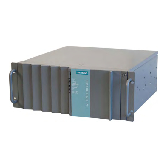
Description Overview SIMATIC Rack PC 847B is an industrial PC in 19" rack format (4HU) with high-performance industrial functionality. ● Wide range of expansion options ● High degree of ruggedness ● Extensive product continuity Figure 3-1 SIMATIC Rack PC 847B SIMATIC Rack PC 847B Operating Instructions, 06/2008, A5E02203168-01... -
Page 12: Areas Of Application
Description 3.2 Areas of application Areas of application SIMATIC Rack PCs provide a high-performance and highly flexible 19" rack PC platform to machine, systems and control cabinet engineering for machine-oriented industrial applications: ● Automatic measurement and control systems for controlling process and machine data ●... -
Page 13: Function
Description 3.4 Function Function ● Integrated programmable monitoring functions (program execution (watchdog), internal housing temperature, fan speed) ● Enhanced diagnostic/messaging by way of Ethernet, E-mail, SMS, and for direct input in SIMATIC software by way of OPC (optional using SIMATIC PC DiagMonitor): –... -
Page 14: Features
Description 3.5 Features Features General features 19” rack, 4 HU Design • Rugged panel-mount housing, all metal • Prepared for mounting telescopic rails • Horizontal and vertical mounting position is possible • Tower installation by means of Tower Kit • Lockable front cover as access protection •... - Page 15 Description 3.5 Features General features Power supply 100 VAC to 240 VAC, wide range; with short-term power failure backup in accordance with NAMUR: Max. 20 ms at 0.85 rated voltage The modules should not occupy more than one slot Monitoring functions Overshoot/undershoot of permissible operating Temperature •...
- Page 16 Description 3.5 Features Optional accessories Intel® Core™2 Duo T5500 (1.66 GHz, 667 MHz FSB, Processor • 2 MB Second Level Cache, EM64T) Intel® Celeron® M 440 (1.86 GHz, 533 MHz FSB, 1 MB • Second Level Cache) RAM expansion Up to 4 GB, dual-channel PROFIBUS/MPI 12 Mbps (isolated potential, compatible to CP 5611) PROFINET...
- Page 17 Description 3.5 Features Languages that can be installed from operating system recovery CD / DVD Language Windows 2000 Windows XP Windows Server 2003 Windows Vista German English French Italian Spanish Japanese Chinese (Hong Kong) Chinese (simplified) Chinese (Taiwan) Korean Optional expansions SIMATIC PC Software tool for monitoring local and remote SIMATIC PCs: DiagMonitor SW...
-
Page 18: Installation
Description 3.6 Installation Installation 3.6.1 External structure Front view of the device (example) Item Description Front panel with vent openings (filter mat and fan behind the front panel). Check the filter mat regularly for soiling and, if appropriate, replace it. Status displays Cover screws On/off button... -
Page 19: Operator Controls
Description 3.6 Installation 3.6.2 Operator Controls Control elements, On/Off and Reset buttons Item Description On/off button For switching the device on or off Reset button The reset button can be operated using a pointed object or a paper clip, for example. -
Page 20: Connecting Elements
Description 3.6 Installation 3.6.3 Connecting elements Interfaces Layout of the interfaces on the rear of the device Item Designation Description DVI or DVI-D connector of the ADD2 card for digital monitors (optional) or DMS59 DMS59 connector for Dual Head graphics card (optional). Audio (input) Connectors for analog audio source, microphone, 3.5 mm phono jack Audio (output) - Page 21 Description 3.6 Installation Layout of the interfaces on the rear of the device (11) PROFIBUS/MPI PROFIBUS interface (RS 485, electrically isolated), 9-pin D-sub socket (optional product characteristic) PROFINET CP 1616 onboard interface, three RJ45 sockets (optional product version) (12) VGA connections (13) DVI-I DVI-I connection...
-
Page 22: Status Displays
Description 3.6 Installation 3.6.4 Status displays Front status displays Display Meaning LEDs Description POWER PC status display isolated from mains YELLOW Standby (hibernating) GREEN PC in operation Display for hard disk no access access GREEN Access No connection ETHERNET 1 * ETHERNET status •... - Page 23 Description 3.6 Installation Front status displays SF PROFINET Status display for CP not available • (optional) CP 1616 onboard CP disabled • No error, communication • established Charging in progress • CP 1616 driver not installed • CP in NDIS mode •...
- Page 24 Description 3.6 Installation Rear status displays Display Meaning Description No cable connected Ethernet LAN 1, 2 Green LED • Link status display Cable disabled • Interface disabled • GREEN Active cable connected No cable connected Yellow LED • Activity status display Cable disabled •...
-
Page 25: Application Planning
● Verify that the shipment contains the complete unit and your separately ordered accessories. Please inform your local dealer of any disagreements or transport damage. ● Please inform Siemens AG by means of the enclosed SIMATIC IPC/PG quality control report form. - Page 26 Application planning 4.2 Unpacking and checking the delivery unit Noting down the device identification data The device can be clearly identified with the help of this identification data in case of repairs or theft. Enter the following data in the table below: ●...
-
Page 27: Ambient And Environmental Conditions
Application planning 4.3 Ambient and environmental conditions Ambient and environmental conditions When you plan your project, you should make allowances for: ● Observe the climatic and mechanical environmental conditions in the technical data in your operating instructions. ● Avoid extreme ambient conditions as far as possible. Protect your device against dust, moisture and heat. -
Page 28: Access Protection
Application planning 4.4 Access protection Access protection The access protection of the rack PC is only enabled if the front door is locked. SIMATIC Rack PC 847B Operating Instructions, 06/2008, A5E02203168-01... -
Page 29: Installing
Installing Installing the device Optional installation locations The device can be mounted horizontally or vertically in control desks, switching cabinets and 19" rack systems. Optional mounting methods Options of mounting the device ● Mounting on cabinet brackets ● Mounting on device bases ●... - Page 30 Installing 5.1 Installing the device Note For vertical operation, install the device on a horizontal metal base and secure it against tilting. The following RITTAL module panels are available: Rittal type TE 7000.620, Rittal type VR 3861.580, Rittal type DK 7063.710. Note the information of the switch cabinet supplier.
-
Page 31: Connecting
Connecting Connecting peripherals Note before connecting NOTICE Connect only peripherals approved for industrial applications according to EN 61000-6-2. Shielded interface cables must be used for interfaces integrated ex factory. Note Hot-plug I/O modules (USB) may be connected while the PC is in operation. CAUTION I/O devices that are incapable of hot-plugging may only be connected after the device has been disconnected from the power supply. -
Page 32: Connecting The Device To Power
Connecting 6.2 Connecting the device to power Connecting the device to power Note before connecting Note The wide-range power supply module is designed for operation on 100 VAC to 240 VAC mains. The setting of the voltage range takes place automatically. WARNING Do not connect or disconnect power and data cables during thunderstorms. - Page 33 Connecting 6.2 Connecting the device to power Localized information Outside of the USA and Canada, operation on a 230 V power supply: This device is equipped with a safety-tested power cord which may only be connected to a grounded shockproof power outlet. If you choose not to use this cable, you must use a flexible cable of the following type: Min.
-
Page 34: Equipotential Bonding
Connecting 6.3 Equipotential bonding Secure the power plug You can secure the power plug in order to avoid unintentional disconnection of the power cord. Steps for securing the power plug Remove the lower left mounting screw (2) on the power supply module. Screw the power plug interlock (1) onto the power supply module WARNING... -
Page 35: Connecting Profinet Strain Relief
Connecting 6.4 Connecting PROFINET strain relief Connecting PROFINET strain relief The PROFINET strain relief provided in the package is used to prevent accidental loosening of the cable from the device. A cable tie (not included in the package) is needed for each interface. - Page 36 Connecting 6.4 Connecting PROFINET strain relief Steps for connecting the PROFINET strain relief Attach the cable using the cable tie. SIMATIC Rack PC 847B Operating Instructions, 06/2008, A5E02203168-01...
-
Page 37: Commissioning
Commissioning Requirements for commissioning ● Before you switch on the device, you should verify that all peripheral devices such the keyboard, mouse, monitor and the power supply are connected. ● The operating system of your device is preinstalled on the hard disk. CAUTION Risk of damage to the device! Make sufficient allowances for the device to acquire room temperature before you put it... -
Page 38: Windows Xp, Vista Security Center
Commissioning 7.3 Windows XP, Vista Security Center After you have entered all necessary information and after the operating system setup is completed, the PC is automatically restarted and displays the user interface of the relevant operating system. From now on, after you switch on the PC, the user interface of the operating system is automatically opened when the startup routine is completed. -
Page 39: Notes On Operation
Commissioning 7.4 Notes on operation Notes on operation 7.4.1 DVD burner The DVD burner drive is an optional feature. Recording methods supported by the disk drive: Disc-at-once, Track-at-once, Session-at-once, Packet writing. You can write to CD-R, CD-RW, DVD+R, DVD-R, DVD-RW, DVD+RW, DVD-RAM and dual-layer media. Burner software In order to utilize full functionality of the DVD burner you need to install additional software (burning software). -
Page 40: Removable Hard Disks
Commissioning 7.4 Notes on operation 7.4.2 Removable hard disks The exchangeable racks support hot-swapping in a RAID1 system. Replacing a hard disk CAUTION Hard drives may only be replaced in an exchangeable rack if the device status display is off. Note The table and information below apply only to the delivery state of the device, that is if no changes or expansions were made. - Page 41 Commissioning 7.4 Notes on operation Note Always replace the faulty drive with a new drive of the same type and capacity. Information about the recovery of the RAID system is available in the next section. 1. Set the key switch to the "OPEN" position. 2.
-
Page 42: 2Hdd System (Optional)
Commissioning 7.4 Notes on operation 7.4.3 2HDD system (optional) When the device ships, the second hard disk is connected to SATA port 2. This hard disk drive is not set up. This gives you the option of backing up your data to this hard disk. For information on hard disk capacities, refer to your order documentation. -
Page 43: Raid System
Commissioning 7.4 Notes on operation 7.4.4 RAID system This is a RAID1 system configuration (mirroring with two hard disks). This configuration enhances system availability as the system is able to continue operation if a hard drive fails, or if there is a cable problem at a channel. Note You can find information regarding Intel RAID controllers in the RAID documentation on the included "Documentation and Drivers"... - Page 44 Commissioning 7.4 Notes on operation RAID system management functions The pre-installed RAID system software offers enhanced functionality for RAID system operation and management. Start the SW by selecting the "Start > Programs > Intel Matrix Storage Manager command. Figure 7-2 Example The "View ->...
- Page 45 Commissioning 7.4 Notes on operation Comments about faults NOTICE Input delay System load may briefly increase due to synchronization when a hard disk has failed, depending on processor load and current hard disk activity. Execution of keyboard and touch screen commands may be briefly delayed in extreme situations.
- Page 46 Commissioning 7.4 Notes on operation The functioning drive can be located using the following pictures and tables. The table and information below apply only to the delivery state of the device, that is if no changes or expansions were made. Figure 7-4 Drives in the exchangeable rack Assigned LED...
- Page 47 Commissioning 7.4 Notes on operation Figure 7-6 Drives in the internal drive bay (with vibration damping) Assigned LED RAID RAID software SATA Installation location Enclosure BIOS interface labeling HDD1 ALARM Port 0 Device Port 0 SATA0 Drive bay (4) drive (1) HDD2 ALARM Port 2 Device Port 2...
- Page 48 Commissioning 7.4 Notes on operation NOTICE Drives in exchangeable racks can be hot-swapped without shutting down the device. Devices without exchangeable rack may only be replaced in shutdown state. The new HDD can be integrated into the RAID system at operating system level by means of the RAID software.
- Page 49 Commissioning 7.4 Notes on operation Integrating a new hard drive Select the "Rescan for Plug and Play Devices" command to find and indicate the new HDD. You can also choose to reboot the device. In this case, the RAID software automatically integrates the new HDD and synchronizes the RAID system.
- Page 50 Commissioning 7.4 Notes on operation The "Rebuild to this Hard drive" command initiates synchronization of the RAID1 system. Figure 7-8 Example SIMATIC Rack PC 847B Operating Instructions, 06/2008, A5E02203168-01...
- Page 51 Commissioning 7.4 Notes on operation Notes on RAID configuration with installed SIMATIC PC DiagMonitor software When creating a RAID-system where SIMATIC PC DiagMonitor software is being used, the Intel Matrix Storage Console may abort the process with the following error message: Solution: Before performing a RAID commissioning, the SIMATIC PC DiagMonitor should be deactivated.
- Page 52 Commissioning 7.4 Notes on operation NOTICE If you do not adhere to the procedure described above, a correct RAID configuration cannot be guaranteed. SIMATIC Rack PC 847B Operating Instructions, 06/2008, A5E02203168-01...
-
Page 53: Integration
Integration Integration Options of integration in existing or planned system environments/networks: Ethernet Wake on LAN and Remote Boot are supported. The integrated Ethernet interfaces (10/100/1000 Mbps) can also be used for communication and data exchange with programmable controllers such as SIMATIC S7. This functionality requires the "SOFTNET S7"... - Page 54 You will find this information on the SIMATIC NET Manual Collection CD. The software package and the documentation are not parts of the development package. Additional information You can find additional information in the catalog and the Siemens online ordering system. Internet address: http://mall.automation.siemens.com SIMATIC Rack PC 847B...
-
Page 55: Profinet
Integration 8.2 PROFINET PROFINET CP 1616 onboard The basic characteristics of the PCS 1616 onboard are: ● Optimized for PROFINET IO ● With Ethernet realtime ASIC ERTEC 400 ● Three RJ45 sockets for connecting terminal devices or addition network components ●... - Page 56 Read this guide if you want to install the NDIS device Device Driver CP16xx.sys driver, CP16xx.sys. Further information You can find the information on specific products in the Internet at the address: http://www.siemens.de/simatic-net SIMATIC Rack PC 847B Operating Instructions, 06/2008, A5E02203168-01...
-
Page 57: Functions
Functions Overview of the monitoring functions Functions implemented: ● Temperature monitoring and over/under-temperature display ● Watchdog ● Fan monitoring ● RAID alarm display Messages of the monitoring modules can be transferred to applications. The SOM software (Safecard On Motherboard) and DiagMonitor software on CD (optional) can be used to handle this functionality. -
Page 58: Watchdog (Wd)
Functions 9.3 Watchdog (WD) The temperature error is retained in memory until temperatures have fallen below the thresholds and are reset by one of the following measures: ● Check whether the ambient temperature limit has been exceeded, or whether the filter is soiled. -
Page 59: Fan Monitoring
Functions 9.4 Fan monitoring Fan monitoring Operation of the front / processor / power unit fans is monitored. The following reactions are triggered when a fan fails: Reaction Option The fan LED switches to red None SIMATIC monitoring software is activated None The fan fault is retained in memory until the cause of the fan failure has been rectified and the error is reset by taking one of the following measures:... -
Page 60: Safecard On Motherboard (Som)
Functions 9.6 Safecard on Motherboard (SOM) Safecard on Motherboard (SOM) This application is used to monitor PC hardware (temperature, watchdog and fans) and to display the current measured values. You can also configure the temperature and fan monitoring functions, and the watchdog function. Your device is equipped with three temperature sensors which are automatically detected by the application. -
Page 61: Expansions And Programming
Liability disclaimer All technical data and approvals apply only to expansion units which are released by SIEMENS. No liability can be accepted for impairment of functions caused by the use of third-party devices or components. - Page 62 Expansions and programming 10.1 Open the device Open the device How to open the device Open the front door Remove the lid screw (Torx T10) Slide the lid towards the rear and remove it SIMATIC Rack PC 847B Operating Instructions, 06/2008, A5E02203168-01...
-
Page 63: Memory Expansion
Expansions and programming 10.2 Memory expansion 10.2 Memory expansion 10.2.1 Installing memory modules Memory expansion options The motherboard features two memory slots under the bus module. You can install 667 MHz SO-DIMM DDR2 memory modules, type PC2-5300, unbuffered, no ECC. This allows you to expand Rack PC memory up to 4 GB, of which you can use approx. - Page 64 Expansions and programming 10.2 Memory expansion Installing a memory module How to install a memory module Open the device. Note the recess (1) (reversal protection) on the connector side of the RAM module. Push the module carefully into the slot until the latches engage. Close the device.
- Page 65 Expansions and programming 10.2 Memory expansion Removing a memory module How to remove a memory module Open the device. Open the left and right latches (1). Start by opening the latches of the top memory module. Pull the memory module out of the slot.
-
Page 66: Installing Expansion Cards
Expansions and programming 10.3 Installing expansion cards 10.3 Installing expansion cards 10.3.1 Notes on the modules Notes on module specifications The device is designed for use with modules to PCI specifications 2.3 or 1.0a. The module supports operation of 5 V and 3.3 V PCI modules. Compliance with the defined mechanical defaults is imperative. -
Page 67: Installing An Expansion Module
Expansions and programming 10.3 Installing expansion cards 10.3.2 Installing an expansion module Preparation Disconnect the device from mains. Installing expansion modules How to install an expansion module (PCI / PCIe format): Open the device Remove the module retainer (3) Remove the relevant steel slot cover (1). -
Page 68: Installing Drives
Expansions and programming 10.4 Installing drives 10.4 Installing drives 10.4.1 Options of installing disk drives In the front drive bay Item Description Front drive bay 5.25" drive bay for DVD drives or exchangeable racks. Floppy Disk 3.5" (FD) In the rear drive bay (with vibration damping) Item Description Rear drive bay... - Page 69 Expansions and programming 10.4 Installing drives Internal drive bay (fixed) Item Description Second drive bay for 3.5" hard disk drives Internal drive bay (fixed) It is not required to remove the drive bay for hard disk installation or removal. SIMATIC Rack PC 847B Operating Instructions, 06/2008, A5E02203168-01...
-
Page 70: Installing And Removing Disk Drives In The Front Drive Bay
Expansions and programming 10.4 Installing drives 10.4.2 Installing and removing disk drives in the front drive bay Preparations 1. Unplug the device from mains and disconnect all cables. 2. Open the device Remove the front drive bay How to remove the front drive bay Remove the mounting screws (2) and (3). - Page 71 Expansions and programming 10.4 Installing drives Installing drives or exchangeable racks How to install a drive Slide the drive (1) into the bay from the front Secure the drive in the drive bay using four screws (2) Reinstall the drive bay Connect the power and data cables to the disk drive.
-
Page 72: Installing And Removing Drives In The Front Drive Bay
Expansions and programming 10.4 Installing drives 10.4.3 Installing and removing drives in the front drive bay Preparations 1. Unplug the device from mains and disconnect all cables. 2. Open the device Removing internal drive bays How to remove the internal drive bay (with vibration damping) Remove the module retainer Remove the four screws (1) Disconnect the power and data... - Page 73 Expansions and programming 10.4 Installing drives Installing a drive How to install a drive Slide the drive into the bay from the front Secure the drive in the drive bay using four screws Reinstall the drive bay Connect the power and data cables to the disk drive.
-
Page 74: Installing / Removing Hard Disk Drives In The Fixed Hard Disk Rack
Expansions and programming 10.4 Installing drives 10.4.4 Installing / removing hard disk drives in the fixed hard disk rack Preparations 1. Unplug the device from mains and disconnect all cables. 2. Open the device Installing a drive How to install a drive Place the drive (1) or (2) onto the drive tray and secure it using four screws (3) or (4). -
Page 75: Maintenance And Service
Disclaimer of liability All technical data and approvals apply only to expansion units which are released by SIEMENS. Siemens disclaims any liability for impairment of functions caused by the use of third-party devices or components. Tools You can perform all installation tasks on the device using TORX T10 and T20 drivers, a 4.5- mm hexagonal wrench (for the interface interlock on the rear panel) and a side cutter. -
Page 76: Preventive Maintenance
Preparing for filter replacement Note You may only use filters of the same type. Information about original spare parts for SIMATIC PCs is available on the Internet at http://www.siemens.com/asis Filter meshes are available under the following order number: A5E01064980. Replacing filters How to replace the filter 1. -
Page 77: Removing The Device / Drive Cooling Fan
Maintenance and service 11.1 Removing and installing hardware components 11.1.4 Removing the device / drive cooling fan Preparing for removal of the device fan Unplug the device from mains. Removing the fan How to remove the device fan Open the front panel door by approximately 45°... - Page 78 Maintenance and service 11.1 Removing and installing hardware components How to remove the device fan Disconnect the fan connector Loosen all body-bound rivets and remove the fan from the bracket SIMATIC Rack PC 847B Operating Instructions, 06/2008, A5E02203168-01...
- Page 79 Maintenance and service 11.1 Removing and installing hardware components Installing the fan NOTICE Always install a fan of the same type! CAUTION Ensure that the arrow on the fan points away from the fan bracket. The fan blows cooling air into the enclosure. Fan mounting position The picture shows the proper fan mounting position.
- Page 80 Maintenance and service 11.1 Removing and installing hardware components Replacing drive fans How to remove the drive fan Remove the four screws (1) and swivel the fan rack (2) out of the enclosure Disconnect the fan cable Remove the two screws (1) of the fan (2) Install the fan in reverse order.
-
Page 81: Replacing The Backup Battery
Risk of damage! The lithium battery may only be replaced with an identical battery or with a type recommended by the manufacturer (Order No.: A5E00047601). Information about original spare parts for SIMATIC PCs is available on the Internet at http://www.siemens.com/asis Disposal CAUTION Used batteries must be disposed of in accordance with local regulations. - Page 82 Maintenance and service 11.1 Removing and installing hardware components Replacing the battery Procedure: How to replace the battery 1. Open the device 2. Pull the battery out of the socket 3. Push the new battery into the socket under slight pressure 4.
-
Page 83: Removing The Power Supply Module
Maintenance and service 11.1 Removing and installing hardware components 11.1.6 Removing the power supply module WARNING Only qualified personnel are allowed to replace the power supply unit. Preparations 1. Isolate the device from mains and disconnect all connecting cables. 2. Open the device. Removing the power supply unit How to remove the power supply unit Disconnect the power cables from the disk... -
Page 84: Removing The Bus Board
Maintenance and service 11.1 Removing and installing hardware components 11.1.7 Removing the bus board Preparation 1. Isolate the device from mains and disconnect all connecting cables. 2. Open the device. Removing the bus board How to remove the bus board 1. -
Page 85: Removing The Operator Panel
Maintenance and service 11.1 Removing and installing hardware components 11.1.8 Removing the Operator Panel Preparation 1. Isolate the device from mains and disconnect all connecting cables. 2. Open the device. Removing the operator panel How to remove the operator panel 1. - Page 86 Maintenance and service 11.1 Removing and installing hardware components How to remove the motherboard Remove the hexagonal bolts at the interfaces. The motherboard is supplied as spare part without processor, memory modules and bus board. SIMATIC Rack PC 847B Operating Instructions, 06/2008, A5E02203168-01...
-
Page 87: Processor Replacement
Maintenance and service 11.1 Removing and installing hardware components 11.1.10 Processor replacement CAUTION The processor may only be replaced by authorized technical personnel. Preparation 1. Unplug the device from mains. 2. Open the device. Removing the processor How to remove the processor 1. - Page 88 Maintenance and service 11.1 Removing and installing hardware components How to remove the processor 3. Removing the processor Installing the processor How to install the processor 1. Inserting the processor NOTICE Make sure that the processor and socket coding match when inserting the processor. 2.
- Page 89 Maintenance and service 11.1 Removing and installing hardware components CAUTION The processor may overheat when the system is in operation! Apply an even, thin film of the heat-conductive paste! 3. Insert the heatsink 4. Secure the heatsink using the four screws: Insert the screws diagonally and tighten them evenly in order to avoid tilting.
-
Page 90: Reinstalling The Software
Maintenance and service 11.2 Reinstalling the software 11.2 Reinstalling the software 11.2.1 General installation procedure If your software is corrupt, you can reinstall it using the recovery CD or DVD, the Documentation and Drivers CD and the Restore DVD. Recovery CD or DVD: The recovery CD/DVD contains the Windows user interface with tools for configuring the hard drives, and for installation of the operating system and the languages supported by the operating system (MUI). -
Page 91: Restoring The Factory State Of The Software Using The Restore Dvd
Maintenance and service 11.2 Reinstalling the software 11.2.2 Restoring the Factory State of the Software Using the Restore DVD You can restore the software to the original factory state using the Restore CD (not included in all package variants). The DVD contains the necessary images and tools for transferring the factory software to the hard disk of your PC. -
Page 92: Installing Windows
Recovery CD or DVD. The boot menu displayed after initialization indicates all boot devices. 2. Select the CD/DVD drive. Follow the instructions on the screen until the "Siemens SIMATIC Recovery" window is displayed. When using the recovery function with Windows Vista, confirm that you want to boot from CD or DVD as soon as you restart. -
Page 93: Setting Up Partitions For Windows 2000, Xp, Server 2003 Operating Systems
1. Boot from the Recovery CD and then follow the on-screen instructions until the Recovery functions window is displayed. 2. Start the DiskPart tool in the "Siemens SIMATIC Recovery“ window. Enter the following commands in the displayed command interface: list disk Displays all available hard disks. - Page 94 Maintenance and service 11.2 Reinstalling the software Note After having modified the HDD configuration using DiskPart, restart the PC for the changes to go into effect. Boot once again from the Recovery CD to format the partitions. Formatting the primary partition 1.
-
Page 95: Installing Microsoft Windows Operating Systems
7. When this operation completed, close the command prompt by entering the exit command. 8. Close the Siemens SIMATIC Recovery window by clicking the "Finish" button. 9. Setup automatically restarts the system and completes the installation of Windows. 10. Follow the on-screen instructions. - Page 96 Maintenance and service 11.2 Reinstalling the software Information for systems with RAID controllers (optional) Unknown additional controllers must be made known to the Windows operating system. 1. Press F6 key within the startup sequence and follow the on-screen instructions. In the next installation phases you are prompted several times to insert a floppy disk which contains the missing RAID driver.
-
Page 97: Setting Up The Language Selection By Means Of The Multilanguage User Interface (Mui)
Maintenance and service 11.2 Reinstalling the software 11.2.4 Setting up the language selection by means of the Multilanguage User Interface (MUI) Preinstalled languages such as German, French, Spanish or Italian can be set up directly. Run MUISETUP.EXE from Recovery CD 2 to install additional languages. The program displays all available languages. -
Page 98: Recovery Of Windows Vista
Maintenance and service 11.2 Reinstalling the software 11.2.5 Recovery of Windows Vista To recover Windows Vista, there is a full graphical user interface available. It may take several minutes before the first input window appears. In this window, you can set the time and currency formats and select the keyboard language. - Page 99 Maintenance and service 11.2 Reinstalling the software Options Meaning Drive options (advanced) Further functions are displayed with which you can set up the hard disk. Load Driver To add new drivers, for example the driver for RAID. Options Meaning Refresh Updating Delete Deleting a partition...
- Page 100 Maintenance and service 11.2 Reinstalling the software When shipped, the partitions are set up as follows: Partition Operating system Name Size File system First Windows Vista SYSTEM 25 GB NTFS not compressed Second Windows Vista DATA Remainder NTFS not compressed Following a reboot, Windows Vista is installed on the hard disk.
-
Page 101: Installing Drivers And Software
Maintenance and service 11.2 Reinstalling the software 11.2.6 Installing drivers and software NOTICE Before you install new drivers or updates for multilingual operating systems, (MUI versions), reset the regional settings for menus and dialogs and the default language to US English. Install the drivers and software from the included "Documentation and Drivers"... -
Page 102: Installing Updates
Maintenance and service 11.2 Reinstalling the software 11.2.9 Installing updates 11.2.9.1 Updating the operating system Windows The latest updates for Windows operating systems are available on the Internet at http://www.microsoft.com NOTICE Before you install new drivers or operating system updates for Windows MUI versions, set the default language to US English in the regional settings for menus and dialogs. -
Page 103: Data Backup
This tool provides comfortable and efficient functions for backup and restoring the full content of Compact Flash cards, of HDDs and of individual partitions (images.) The software can be ordered from the Siemens online ordering system. For detailed information about SIMATIC PC/PG Image Creator, refer to the corresponding product documentation. -
Page 104: Cp 1616 Onboard
Maintenance and service 11.2 Reinstalling the software 11.2.11 CP 1616 onboard NDIS device driver Read the information in description provided by Installation_CP16xx.pdf on the supplied "Documentation and Drivers" CD. PROFINET IO Read the information regarding the SIMATIC devices and SIMATIC NET documentation listed in the "Integration"... -
Page 105: Interrupt, Error And System Messages
Interrupt, error and system messages 12.1 Boot error messages BIOS first performs a Power On Self Test (POST) within the boot routine to verify proper operation of certain functional units of the PC. If an error is detected within this phase, BIOS outputs a beep code based on the current test result. - Page 106 Interrupt, error and system messages 12.1 Boot error messages On-screen error message Meaning / tip System RAM Failed at offset: Memory error. Contact Technical Support. Shadow RAM Failed at offset: Memory error. Contact Technical Support. Extended RAM Failed at offset: Memory error.
-
Page 107: Bios Post Codes
Interrupt, error and system messages 12.2 BIOS POST codes 12.2 BIOS POST codes The section below lists the POST codes relevant to users in chronological order of occurrence: Contact Customer Support for information on all other POST codes. Display Meaning Description To correct or avoid errors (hex) - Page 108 Interrupt, error and system messages 12.2 BIOS POST codes Special codes The following Beep Codes are available in addition to the POST Codes listed: ● 3 x short INSERT key is pressed at system startup: If an external graphics card on the bus board is not detected, you can try to activate it by pressing the INSERT key.
-
Page 109: Troubleshooting/Faqs
Troubleshooting/FAQs 13.1 General problems This chapter provides you with tips on how to localize and troubleshoot frequently occurring problems. Problem Possible cause To correct or avoid error The device is not operational No power supply Check the power supply, and the power cord / connector Check the environment conditions Device operation is non-compliant... - Page 110 Troubleshooting/FAQs 13.1 General problems Problem Possible cause To correct or avoid error 1. Press <F2> within the boot sequence to open Incorrect time and/or date on BIOS Setup. the PC. 2. Adjust the time and date in BIOS Setup. Although the BIOS setting is The backup battery is low.
- Page 111 Troubleshooting/FAQs 13.1 General problems Error displays on the front panel Front LED Possible cause Details about the error display Red WATCHDOG LED is lit Watchdog has triggered See section 9.3 Red TEMP LED is lit Excess temperature in the device See section 9.2 Red FAN LED is lit Fan failure...
-
Page 112: Problems When Using Modules Of Third-Party Manufacturers
If the error no longer occurs, the Connector pin assignments • third-party module was the cause of the fault. Replace the deviate thrid-party module with a Siemens module or contact the No "Reset Configuration" in • module supplier. BIOS SETUP Force a "Reset Configuration"... -
Page 113: Technical Data
Technical data 14.1 General specifications General specifications Order number 6ES7643-8... (refer to the ordering documents for details) Dimensions 430.4 x 177.4 x 444.4 (WxHxD in mm) Detailed dimensional specifications are found in the "Dimensional drawings" section. Weight min. 16 kg, max. 23 kg Supply voltage (V 100 VAC to 240 VAC, wide range;... - Page 114 Technical data 14.1 General specifications General specifications Noise immunity on signal lines ± 1 kV;(according to IEC 61000-4-4; burst; length < 3 m) ± 2 kV; (according to IEC 61000-4-4; burst; length > 3 m) ± 2 kV; (according to IEC 61000-4-5; surge asym. length >...
- Page 115 Technical data 14.1 General specifications General specifications Motherboard Chipset Intel 945GM RAID (on-board) Intel ICH7R with Intel Storage Manager software Intel Celeron M 440 Processor • 1.86 GHz, 533 MHz FSB' 1024 KB Second Level Cache Intel Core 2 Duo T5500 •...
- Page 116 Technical data 14.1 General specifications General specifications Drives (for configuration details, refer to the order documentation) Floppy drive 3.5" (1.44 MB) 3.5" SATA 300, 80 / 160 GB DVD ROM 5.25" ATAPI, UDMA33 Read: DVD ROM: Single layer 16x, Dual Layer 8x DVD+R/RW, DVD-R/RW 8x, DVD-RAM 2x CD-ROM, CD-R 32x, CD-RW 20x DVD burner...
- Page 117 Technical data 14.1 General specifications General specifications Interfaces COM1 Serial interface 1 (V.24), 9-pin D-sub connector COM2 Serial interface 2 (V.24), 9-pin D-sub connector LPT1 Parallel interface (Standard, EPP and ECP mode) Connection for parallel interface printer VGA (motherboard) Connection for analog monitor, 15-pin D-sub socket 1x DVI-D with ADD card (optional) For connecting a digital monitor 2x DVI-D/VGA with Dual-Head...
- Page 118 Technical data 14.1 General specifications General specifications Approvals / manufacturer's declarations cULus 60950 Industry: Emitted interference EN 610 0-6-4:2001, noise immunity EN 61000-6-2:2005 Electrical isolation within the safety extra-low voltage circuit (SELV) Mechanical interference must be safely excluded within the burning operation. Restrictions of HDD mounting on the side panel: When mounting the device on telescopic rails, the values 10 to 58 Hz: 0.019 mm, 58 to 200 Hz: 3 may not be exceeded.
-
Page 119: Power Requirements Of Components (Maximum Values)
Technical data 14.2 Power requirements of components (maximum values) 14.2 Power requirements of components (maximum values) Base system Component Voltage +5 V +3.3 V +12 V -5 V -12 V 5 Vaux Motherboard 0.8 A 0.03 A 0.3 A Dual-Core processor with heatsink 2.3 A Core 2 Duo processor with heatsink 2.6 A... -
Page 120: Power Supply (Ac)
Technical data 14.3 Power supply (AC) 14.3 Power supply (AC) Output voltage Voltage Max. current Voltage stability + 12 V 15 A +/- 5 % + 12 V 15 A +/- 5 % - 12 V 0.2 A +/- 10 % + 5 V 26 A + 5 % / - 4 %... -
Page 121: Dimensional Drawings
Dimensional drawings 15.1 Dimensional drawing of the device SIEMENS POWER ETHERNET 1 ETHERNET 2 PROFIBUS/MPI WATCHDOG TEMP HDD1 ALARM HDD2 ALARM Figure 15-1 Dimensional drawing SIMATIC Rack PC 847B Operating Instructions, 06/2008, A5E02203168-01... -
Page 122: Dimensional Drawing For The Use Of Telescopic Rails
Dimensional drawings 15.2 Dimensional drawing for the use of telescopic rails 15.2 Dimensional drawing for the use of telescopic rails Figure 15-2 Dimensional drawing for the use of telescopic rails SIMATIC Rack PC 847B Operating Instructions, 06/2008, A5E02203168-01... -
Page 123: Dimensional Drawings For Installation Of Expansion Modules
Dimensional drawings 15.3 Dimensional drawings for installation of expansion modules 15.3 Dimensional drawings for installation of expansion modules Figure 15-3 Maximum mountable PCI/PCIe module (shown without slot bracket and retainer) PCIe Meaning DIM A (mm/inch) 106.68 / 4.2 111.15 / 4.38 Lower edge of module to upper edge of module DIM B (mm/inch) 111.94 / 4.41... - Page 124 Dimensional drawings 15.3 Dimensional drawings for installation of expansion modules SIMATIC Rack PC 847B Operating Instructions, 06/2008, A5E02203168-01...
-
Page 125: Detailed Descriptions
Detailed descriptions 16.1 Motherboard 16.1.1 Structure and functions of the motherboard Core components of the motherboard: processor and chipset, three slots for memory modules, internal and external interfaces, Flash BIOS and the backup battery. Figure 16-1 Motherboard Processor with fan Slot for the bus board Two memory module slots Backup battery... -
Page 126: Technical Features Of The Motherboard
Parameters Chipset Single chipset 945GM and ICH7/ICH7R BIOS Update by means of software Phoenix First BIOS, modified by Siemens Intel Core 2 Duo / Celeron M - Upgradeable (design FC PGA479) - Multimedia support - On-board L2-Cache with 1M/2M/4M, CPU... - Page 127 Detailed descriptions 16.1 Motherboard Component / interface Description Parameters Ethernet (two 10BaseT/100Base- - 10/100/1000 Mbps, electrically isolated interfaces) TX/1000Base-TX (Intel Tekoa 82573L) Electrical isolation within the safety extra-low voltage circuit (SELV) Optional product feature Depends on the CPU type Depends on the selected device configuration SIMATIC Rack PC 847B Operating Instructions, 06/2008, A5E02203168-01...
-
Page 128: Position Of The Interfaces On The Motherboard
Detailed descriptions 16.1 Motherboard 16.1.3 Position of the interfaces on the motherboard Interfaces The Rack PC motherboard contains the following interfaces: ● Interfaces for the connection of external devices ● Interfaces for internal components (drives, bus boards etc.) The diagram below shows the position of the internal and external interfaces on the motherboard. -
Page 129: External Interfaces
Detailed descriptions 16.1 Motherboard 16.1.4 External interfaces Interface Position Connector Description COM1 External X616 9-pin, standard connector COM2 External X615 9-pin, standard connector LPT1 External X609 25-pin, standard socket PS/2 mouse External X21 (7 to 12) 6-pin, miniature DIN socket (top socket) PS/2 keyboard External X21 (1 to 6) - Page 130 Detailed descriptions 16.1 Motherboard Parallel interface LPT1, X609 Parallel interface Pinno. Short name Meaning Input / output / Strobe (CLK) Data message Output (open collector) Data - Bit 0 Data channel 0 Output (TTL level) Data - Bit 1 Data channel 1 Output (TTL level) Data - Bit 2 Data channel 2...
- Page 131 Detailed descriptions 16.1 Motherboard PS/2 keyboard interface, X21 1 to 6 PS/2 Pin no. Short name Meaning Input / output Data channel, keyboard Input/output – Not used – Ground – P5VFK + 5 V (fused) Output Clock channel, Input/output keyboard –...
- Page 132 Detailed descriptions 16.1 Motherboard PROFIBUS/MPI interface, X600 PROFIBUS/MPI interface Pinno. Short name Meaning Input / output – Not used – – Not used – LTG_B Signal line B of MPI module Input/output RTS_AS RTSAS, control signal for received data Input stream.
- Page 133 Detailed descriptions 16.1 Motherboard PROFINET LAN X1 Port P1, P2, P3 PROFINET interface Pinno. Short name Meaning Input / output Receive data * Input Receive data * Input Send data * Output 4, 5 SYMR Internal 75 Ohm terminating resistor Receive data * Output 7, 8...
- Page 134 Detailed descriptions 16.1 Motherboard Ethernet LAN connection, X40, X41 Ethernet LAN connection Pinno. Short name Meaning Input / output BI_DA+ Bi-directional data A+ Input / output BI_DA- Bi-directional data A- Input / output BI_DB+ Bi-directional data B+ Input / output BI_DC+ Bi-directional data C+ Input / output...
- Page 135 Detailed descriptions 16.1 Motherboard VGA interface, X303 VGA interface Pinno. Short name Meaning Input / output Output Green Output Blue Output – Not used – Ground – Ground – Ground – Ground – + 5 V + 5 V (fused) Output Ground –...
- Page 136 Detailed descriptions 16.1 Motherboard DVI interface DVI interface Pinno. Short name Meaning Input / output Ground – Ground – TX2N TDMS data 2- Output TX2P TDMS data 2+ Output Ground – Not used – Not used – DDC CLK DDC clock Input / output DDC CLK DDC data...
- Page 137 Detailed descriptions 16.1 Motherboard Microphone interface, X60 Microphone interface Pin no. Short name Meaning Input / output right Right channel Input sense Switch contact for device identification Input Ground for identification Output left Left channel Input Analog ground Output Logic ground Output Line Out interface, X61 Line Out interface...
-
Page 138: Internal Ports
Detailed descriptions 16.1 Motherboard 16.1.5 Internal ports Pin assignment of the internal interfaces Interface Position Connector Description Memory Internal X19, X20 2 SODIMM sockets, 64-bit Processor Internal Socket for FCPGA processor Bus expansion Internal Bus expansion socket, used by PCI and PCIe bus signals Power supply Internal... - Page 139 Detailed descriptions 16.1 Motherboard Pin assignment of the internal USB connector, X420 Pin no. Short name Meaning Input / output + 5 V (fused) Output – – -Data USB1 Data channel Input / output -Data USB3 Data channel Input / output +Data USB1 Data channel Input / output...
- Page 140 Detailed descriptions 16.1 Motherboard Pin assignment of the HDD fan interface, X131 Pin no. Short name Meaning Input / output Ground 5 V to +12 V, regulated Output Tacho signal Monitoring signal Input Reserved Pin assignment of the front fan interface, X132 Pin no.
- Page 141 Detailed descriptions 16.1 Motherboard Pin assignment of the PEG interface (PCIe X16 socket), X610 Signal Pin no. Pin no. Signal P12V P12V P12V P12V P12V P12V SMB_CLK2 n.c. SMB_DATA2 n.c. n.c. P3V3 n.c. n.c. P3V3 AUX_3V P3V3 WAKE2 PCIE_RESET_L n.c. PCIE0_ECLK PCIEX16_TX_P(15) PCIE0_ECLK_N...
- Page 142 Detailed descriptions 16.1 Motherboard Signal Pin no. Pin no. Signal PCIEX16_TX_P(9) PCIEX16_TX_N(9) PCIEX16_RX_P(9) PCIEX16_RX_N(9) PCIEX16_TX_P(8) PCIEX16_TX_N(8) PCIEX16_RX_P(8) MCH_CFG_20 PCIEX16_RX_N(8) PCIEX16_TX_P(7) n.c. PCIEX16_TX_N(7) PCIEX16_RX_P(7) PCIEX16_RX_N(7) PCIEX16_TX_P(6) PCIEX16_TX_N(6) PCIEX16_RX_P(6) PCIEX16_RX_N(6) PCIEX16_TX_P(5) PCIEX16_TX_N(5) PCIEX16_RX_P(5) PCIEX16_RX_N(5) PCIEX16_TX_P(4) PCIEX16_TX_N(4) PCIEX16_RX_P(4) PCIEX16_RX_N(4) PCIEX16_TX_P(3) PCIEX16_TX_N(3) PCIEX16_RX_P(3) PCIEX16_RX_N(3) PCIEX16_TX_P(2) PCIEX16_TX_N(2) PCIEX16_RX_P(2)
- Page 143 Detailed descriptions 16.1 Motherboard Pin assignment of the PCI-PCIe interface (PCIe X16 socket), X10 Signal Pin no. Pin no. Signal N12V AUX_5V P12V P12V P12V P12V PCI_INT_N(7) PCI_INT_N(6) PCI_INT_N(5) PCI_INT_N(8) PCI_REQ_N(4) PCI_REQ_N(3) PCI_GNT_N(4) PCI_GNT_N(3) PCI0_PCLK AUX_3V PLT_RST_N_BUFF PCI1_PCLK PCI_GNT_N(1) PCI_REQ_N(1) PCI_GNT_N(2) PCI_REQ_N(2) PCI_AD(31)
- Page 144 Detailed descriptions 16.1 Motherboard Signal Pin no. Pin no. Signal P3V3 PCI_CBE_N(1) PCI_AD(15) PCI_AD(14) P3V3 PCI_AD(13) PCI_AD(12) PCI_AD(11) PCI_AD(10) PCI_AD(9) PCI_AD(8) PCI_CBE_N(0) PCI_AD(7) P3V3 P3V3 PCI_AD(6) PCI_AD(5) PCI_AD(4) PCI_AD(3) PCI_AD(2) PCI_AD(1) PCI_AD(0) PCIE_1X4X AUX_5V WAKE1 PLT_RST_N_PCIE4X PS_ON PS_PWRGD n.c. n.c. PCIE_TX_P(1) PCIE_TX_N(1) PCIE_RX_P(1)
-
Page 145: Bus Board
Detailed descriptions 16.2 Bus board 16.2 Bus board 16.2.1 Bus board - Layout and principle of operation The bus board is designed as a link between the motherboard and the expansion modules. It is mounted by means of four screws. This bus board is available in two versions: Variant 1: Low end (8 slots) 7 PCI slots, 3 of upstream of the PCI2PCI bridge,... - Page 146 Detailed descriptions 16.2 Bus board PCIe-x16 (PEG slot, slot 1) High-end equipment variant with 3 x PCIe x4 slots (slot 2, 3, 4), with PCIe switch and circuit Primary PCI bus: 3 slots (slots 5, 6, 7) PCI2PCI bridge Secondary PCI bus: 4 slots (slots 8, 9, 10, 11) BTX power connector PCI, PCIe 4lane Riser PEG riser...
- Page 147 Detailed descriptions 16.2 Bus board Interrupt assignment of the slot connectors on the bus board SIMATIC Rack PC 847B Operating Instructions, 06/2008, A5E02203168-01...
-
Page 148: Exclusive Pci Hardware Interrupt
Detailed descriptions 16.2 Bus board 16.2.2 Exclusive PCI hardware interrupt Applications demanding high-performance interrupt handling require high-speed hardware interrupt reaction. The PCI hardware interrupt should only be used by one resource in order to ensure high-speed reaction of the hardware. Setting up an exclusive interrupt on the device (only APIC mode) An exclusive interrupt can only be set and used for PCI slot 5 or 8 and 6 or 9. -
Page 149: Pin Assignment Of The Bus Board Connectors
Detailed descriptions 16.2 Bus board 16.2.3 Pin assignment of the bus board connectors Pinout for PCI slots (slots 5, 6, 7, 8, 9, 10, 11) 5V System Environment Side B Side A -12 V TRST# +12 V Ground +5 V +5 V +5 V INTA#... - Page 150 Detailed descriptions 16.2 Bus board Ground STOP# LOCK# +3.3 V PERR# SDONE +3.3 V SBO# SERR# Ground +3.3 V C/BE[1]# AD[15] AD[14] +3.3 V Ground AD[13] AD[12] AD[11] AD[10] Ground Ground AD[09] CONNECTOR KEY CONNECTOR KEY AD[08] C/BE[0]# AD[07] +3.3 V +3.3 V AD[06] AD[05]...
- Page 151 Detailed descriptions 16.2 Bus board Pinout of the PEG interface (PCIe x16 socket), Slot 1 Signal Pin no. Pin no. Signal P12V P12V P12V P12V P12V P12V SMB_CLK2 n.c. SMB_DATA2 n.c. n.c. P3V3 n.c. n.c. P3V3 AUX_3V P3V3 WAKE2 PCIE_RESET_L n.c.
- Page 152 Detailed descriptions 16.2 Bus board Signal Pin no. Pin no. Signal PCIEX16_TX_P(9) PCIEX16_TX_N(9) PCIEX16_RX_P(9) PCIEX16_RX_N(9) PCIEX16_TX_P(8) PCIEX16_TX_N(8) PCIEX16_RX_P(8) MCH_CFG_20 PCIEX16_RX_N(8) PCIEX16_TX_P(7) n.c. PCIEX16_TX_N(7) PCIEX16_RX_P(7) PCIEX16_RX_N(7) PCIEX16_TX_P(6) PCIEX16_TX_N(6) PCIEX16_RX_P(6) PCIEX16_RX_N(6) PCIEX16_TX_P(5) PCIEX16_TX_N(5) PCIEX16_RX_P(5) PCIEX16_RX_N(5) PCIEX16_TX_P(4) PCIEX16_TX_N(4) PCIEX16_RX_P(4) PCIEX16_RX_N(4) PCIEX16_TX_P(3) PCIEX16_TX_N(3) PCIEX16_RX_P(3) PCIEX16_RX_N(3) PCIEX16_TX_P(2) PCIEX16_TX_N(2)
-
Page 153: Pinout For Pci Express Slot X4 (Slots 2, 3, 4)
Detailed descriptions 16.2 Bus board 16.2.4 Pinout for PCI Express slot x4 (slots 2, 3, 4) Side B Side A P12V PRSNT1_N P12V P12V P12V SMBCLK PTCK SMBDAT PTDI PTDO P3V3 PTMS PTRST_N P3V3 Aux_3V3 P3V3 PCIE_Wake_N PCI RST_N Reserved PCIE_TX_P(1) PCIE_TX_N(1) PCIE_RX_P(1) -
Page 154: Displays And Operator Panel
Detailed descriptions 16.3 Displays and operator panel 16.3 Displays and operator panel 16.3.1 Operating panel - Layout and function The operator panel is interconnected with the motherboard using a 26-pin connecting cable. Operator panel Item Description USB port (only the top USB contact is used) 9-pole pin header Connection to the motherboard... -
Page 155: System Resources
Detailed descriptions 16.4 System resources 16.4 System resources 16.4.1 Currently allocated system resources All system resources (hardware addresses, memory configuration, allocation of interrupts, DMA channels) are assigned dynamically by the Windows OS, depending on the hardware configuration, drivers and connected external devices. You can view the current configuration of system resources or possible conflicts with the following operating systems: Windows NT 4.0 Start >... -
Page 156: System Resources Used By The Bios/Dos
Detailed descriptions 16.4 System resources 16.4.2 System resources used by the BIOS/DOS The following table describes the system resources for the factory state of the device. 16.4.2.1 I/O address allocation I/O address (hex) Size Description of the basic function Possible alternative (bytes) function from... - Page 157 Detailed descriptions 16.4 System resources I/O address (hex) 0300 031F Not used 0320 032F Not used 0330 033F Not used 0340 035F Not used 0360 0367 Not used 0370 0371 0372 0375 Not used 0376 0376 Secondary EIDE channel 0378 037F LPT 1 Switchable in Setup,...
-
Page 158: Interrupt Assignments
Detailed descriptions 16.4 System resources 16.4.2.2 Interrupt assignments The functions are assigned different interrupts, depending on the operating system. A distinction is made between the PIC and APIC modes. SIMATIC Rack PC 847B Operating Instructions, 06/2008, A5E02203168-01... -
Page 159: Memory Address Assignments
Detailed descriptions 16.4 System resources PCI / PCIe cards and the on-board PCI / PCIe devices require PCI interrupt channels. These interrupt channels can be shared and are plug-and-play compatible, that is, several devices can share the same interrupt. The IRQ is assigned automatically. PCI interrupt channels must be derived from the PIC interrupt pool, that is PCI modules also use PIC resources. -
Page 160: Bios Setup
Detailed descriptions 16.5 BIOS Setup 16.5 BIOS Setup 16.5.1 Overview BIOS Setup program BIOS Setup program is stored in ROM BIOS. System configuration data are stored in battery-backed RAM of the device. SETUP can be used to define the hardware configuration (for example, the hard disk type) and system properties. -
Page 161: Starting Bios Setup
Detailed descriptions 16.5 BIOS Setup 16.5.2 Starting BIOS Setup Starting BIOS SETUP Run SETUP as follows: 1. Reset the device (warm or cold restart). With the default setting of your device, the display shown below appears following power- on, for example: 2. -
Page 162: Bios Setup Menus
Detailed descriptions 16.5 BIOS Setup 16.5.3 BIOS Setup menus The various menus and submenus are listed on the next pages. You can obtain information on the selected SETUP item from the "item-specific help" part of the respective menu. Figure 16-3 BIOS SETUP Menu (example) (1) Header (4) Help view... - Page 163 Detailed descriptions 16.5 BIOS Setup Menu Meaning Main Set the system functions in this mask Advanced Set advanced system configurations in this dialog Security Dialog for setting security functions such as the password. Power Power-saving functions can be selected here Boot Define boot priorities in this dialog.
-
Page 164: Main Menu
Detailed descriptions 16.5 BIOS Setup 16.5.4 Main menu Figure 16-4 SETUP main menu (example) (1) Selectable submenu Settings in the main menu In the main menu, you can navigate up and down to select the following system configuration fields using the [↑] up and [↓] down cursor keys: Field Meaning System Time... - Page 165 Detailed descriptions 16.5 BIOS Setup System Time and System Date System Time and System Date indicate the current values. You can change the values using the [+] and [–] keys after having selected the corresponding field Hour: Minute: Second and for the date Month/Day/Year You can navigate between the entries in the date and time fields (for example, from hour to minute) using the tab key.
- Page 166 Detailed descriptions 16.5 BIOS Setup IDE Channel 0 Master, IDE Channel 0 Slave The system jumps to the following submenu when you select this type of menu field: Figure 16-5 IDE Channel 0 Master (example) Type [User] Select “User” to enter a user-specific definition of the hard disk type.
- Page 167 Detailed descriptions 16.5 BIOS Setup LBA Mode The "Enabled" setting at the "LBA Mode Control" (enabled, disabled) option means Control that hard disk capacities greater than 528 MB are supported. The value depends on the drive and should only be set by way of "Auto" setting at the "Type" field. 32-bit I/O The type of access to the drive is determined in the 32-bit I/O field Disabled...
- Page 168 Detailed descriptions 16.5 BIOS Setup Type [User] Select “User” to enter a user-specific definition of the hard disk type. Configure all the other options, for example, Cylinder, Heads, Sectors/Track, or other properties of the hard disk drive. [Auto] The parameters which you can select in this dialog are usually saved to the respective IDE drive.
- Page 169 Detailed descriptions 16.5 BIOS Setup "Memory Cache" field The following shortcut menu appears when you select the "Memory cache" option in the main menu: Figure 16-7 "Memory Cache" field The term cache is used to denote a high-speed memory buffer between the CPU and memory (DRAM).
- Page 170 Detailed descriptions 16.5 BIOS Setup "Boot Options" field The following submenu appears when you select the "Boot Options" from the main menu: Figure 16-8 "Boot Options" field (example) Quick Boot Mode Certain hardware tests are skipped in order to accelerate the boot sequence.
- Page 171 Detailed descriptions 16.5 BIOS Setup Example of a Summary Screen: Figure 16-9 Summary screen (example) The summary screen appears when system startup is completed. SIMATIC Rack PC 847B Operating Instructions, 06/2008, A5E02203168-01...
- Page 172 Detailed descriptions 16.5 BIOS Setup "Keyboard Features" field The following submenu appears when you select the "Keyboard Features" field from the main menu: Figure 16-10 "Keyboard Features" submenu (example) Numlock Switches Numlock on or off after Power On. This status is saved to non-volatile memory if "Auto"...
- Page 173 Detailed descriptions 16.5 BIOS Setup "Hardware Options" field One of the following submenus appears when you select the "Hardware Options" field from the main menu: Figure 16-11 "Hardware Options" field (example for PROFIBUS) SIMATIC Rack PC 847B Operating Instructions, 06/2008, A5E02203168-01...
- Page 174 Detailed descriptions 16.5 BIOS Setup Figure 16-12 "Hardware Options" field (example for PROFINET) Set the parameters of interfaces installed on the motherboard at this field. Entry Meaning PCI-MPI/DP * [Enabled] PROFIBUS onboard is enabled [Disabled] PROFIBUS onboard is disabled Onboard [Enabled] CP 1616 onboard is enabled Profinet *...
- Page 175 Detailed descriptions 16.5 BIOS Setup Entry Meaning SafeCard [Enabled] On-board monitoring functions are enabled. functions [Disabled] No monitoring functions The relevant driver and application must be started for operation of the monitoring functions. Fan Control [Enabled] The fan speed is temperature-controlled [Disabled] The fan always runs at full speed.
-
Page 176: Advanced Menu
Detailed descriptions 16.5 BIOS Setup 16.5.5 Advanced Menu Menu layout Figure 16-13 "Advanced" menu (example) Settings in the Advanced menu HPET Support [Disabled] High-resolution timer for multimedia disabled. [Enabled] High-resolution timer for multimedia enabled. Core Multi- [Disabled] Core Multi-Processor disabled Processing * [Enabled] Core Multi-Processor enabled... - Page 177 Detailed descriptions 16.5 BIOS Setup Reset [Yes] All Plug-and-Play data are deleted and the configuration is Configuration initialized at the next system restart. The entry is then reset to Data [No]. System components which do not support Plug-and-Play have to be entered manually. [No] The Plug-and-Play system components are initialized after the next system start.
- Page 178 Detailed descriptions 16.5 BIOS Setup "SATA/PATA Configuration" submenu Figure 16-14 SATA/PATA Configuration PATA Controller [Enabled] Disables or enables the PATA controller [Disabled] SATA Controller mode [Enhanced] 4 SATA ports are available in Native Mode [Compatible] Drives on SATA Port 0, 2 => SATA drives are emulated as primary PATA master/slave.
- Page 179 Detailed descriptions 16.5 BIOS Setup "I/O Device Configuration" submenu Figure 16-15 "I/O Device Configuration" submenu The resources used by an interface are released by disabling this interface. It is advisable not to change the default I/O addresses and interrupts. Internal printer port LPT1 Mode Use this setting to set the operating mode of the printer port.
- Page 180 Detailed descriptions 16.5 BIOS Setup "PCI Configuration" submenu Figure 16-16 "PCI Configuration" submenu SIMATIC Rack PC 847B Operating Instructions, 06/2008, A5E02203168-01...
- Page 181 Detailed descriptions 16.5 BIOS Setup "PCI Devices" field If the PCI devices field is selected, the following submenu appears: Figure 16-17 "PCI Devices" field ROM Scan Option [Enabled] The ROM option of the PCI module (if present) is enabled [Disabled] The ROM option of a PCI module is disabled.
- Page 182 Detailed descriptions 16.5 BIOS Setup "ICH USB Control Sub-Menu" Figure 16-18 "ICH USB Control Sub-Menu" USB 2.0 Mode Enabled USB 2.0 devices are supported. Disabled USB 2.0 devices are not supported SIMATIC Rack PC 847B Operating Instructions, 06/2008, A5E02203168-01...
-
Page 183: Security Menu
Detailed descriptions 16.5 BIOS Setup 16.5.6 Security menu You can only edit the fields enclosed in square brackets. Two passwords can be assigned to protect your PC from unauthorized use. The Supervisor password can be used to restrict access to the hard disks. Figure 16-19 Security menu User password is Disabled... - Page 184 Detailed descriptions 16.5 BIOS Setup Diskette access This mode of protection is not enabled unless "Password on boot " is [enabled]. [Supervisor] Diskette access is not possible unless the supervisor password was entered during system boot. [User] Diskette access is not possible unless the user password was entered during system boot.
-
Page 185: Power Menu
Detailed descriptions 16.5 BIOS Setup 16.5.7 Power menu This menu has the following layout: Figure 16-20 Power menu (example) You can use the Power menu to set various (environment-friendly) power-saving modes: Resume On Time [On] This function is used to switch the device on automatically at the time specified at the bottom. -
Page 186: Boot Menu
Detailed descriptions 16.5 BIOS Setup 16.5.8 Boot menu This menu allows you to define the boot priority of the devices. Figure 16-21 Boot menu SIMATIC Rack PC 847B Operating Instructions, 06/2008, A5E02203168-01... - Page 187 Detailed descriptions 16.5 BIOS Setup Figure 16-22 Boot Menu This screen shows all available boot sources. The boot source with highest boot priority shown at the top. To change the boot sequence: Select the group using the ↑↓ keys, move to device the desired position using the + or - keys.
-
Page 188: Version Menu
Detailed descriptions 16.5 BIOS Setup 16.5.9 Version menu This menu contains system information which should be made available to Technical Support. Figure 16-23 Version menu SIMATIC Rack PC 847B Operating Instructions, 06/2008, A5E02203168-01... -
Page 189: Exit Menu
Detailed descriptions 16.5 BIOS Setup 16.5.10 Exit menu You always exit BIOS Setup in this menu. Figure 16-24 Exit menu Exit Saving Changes All changes are saved and the system is restarted with the new parameters. Exit Discarding Changes All changes are discarded and the system is restarted with the old parameters. -
Page 190: Default Bios Setup Entries
Detailed descriptions 16.5 BIOS Setup 16.5.11 Default BIOS Setup entries Documenting your device configuration If you have changed any default settings in Setup, you can enter them in the following table. You can then refer to these entries for any future hardware modifications. Note Print out the table below and keep the pages in a safe place once you have made your entries. - Page 191 Detailed descriptions 16.5 BIOS Setup Hardware Options PCI - MPI / DP Enabled PROFINET Enabled MAC Address Layer1 000E8C80A63E (example) MAC Address Profinet 000E8C80A63F (example) On-board Ethernet 1 Enabled On-board Ethernet 1 Address 000E8C80A63D (example) On-board Ethernet 1 Remote Disabled Boot On-board Ethernet 2 Enabled...
- Page 192 Detailed descriptions 16.5 BIOS Setup ICH USB Control Sub-Menu USB 2.0 Support Enabled PCI Configuration PCI Device Slot 5 ROM Scan Option Enabled Enable Master Enabled Latency timer Default PCI Device Slot 6 ROM Scan Option Enabled Enable Master Enabled Latency timer Default PCI Device Slot 7...
- Page 193 Detailed descriptions 16.5 BIOS Setup Power Resume On Time Resume Time 00:00:00 After Power Failure Last State Boot Boot priority order Excluded from boot order Version SIMATIC SIMATIC Rack PC 847B BIOS Version BIOS Number MPI/DP Firmware CPU Type Intel® Core 2 CPU CPU Speed CPU ID Code Revision...
-
Page 194: Communication Processor Cp 1616 Onboard
Detailed descriptions 16.6 Communication processor CP 1616 onboard 16.6 Communication processor CP 1616 onboard 16.6.1 Introduction The CP 1616 onboard allows the connection of industrial PCs to Industrial Ethernet. The basic characteristics of the PCS 1616 onboard are: ● Optimized for PROFINET IO ●... -
Page 195: Typical Communication Partners
Detailed descriptions 16.6 Communication processor CP 1616 onboard 16.6.1.2 Typical Communication Partners CP 1616 onboard as an IO controller The following diagram shows a typical application: CP 1616 onboard as PROFINET IO controller on the IO controller layer. The IO base controller user program runs on the PC. This program accesses the functions of the IO base user program interface. - Page 196 Detailed descriptions 16.6 Communication processor CP 1616 onboard CP 1616 onboard as IO device The following diagram shows a typical application: Two PCs each with a CP as a PROFINET IO device on the IO device layer. A PC with a CP as PROFINET IO controller, a SIMATIC S7-400 with a CP 443-1 as PROFINET IO controller and two SIMATIC S7 ET 200S PROFINET IO devices are also connected in the network.
-
Page 197: Firmware Loader
Detailed descriptions 16.6 Communication processor CP 1616 onboard 16.6.2 Firmware loader Scenario for using the firmware loader The CP 1616 onboard is supplied with the latest version of the firmware. If new functions become available due to product development, you can make them available by performing a firmware download. -
Page 198: Loading Firmware
CAUTION Ensure that the loader file you are using for the update is suitable for the version of firmware on your module. If you have any doubts, contact your local Siemens consultant. CAUTION Be aware that aborting the loading process may result in an inconsistent state in your module. - Page 199 Detailed descriptions 16.6 Communication processor CP 1616 onboard NOTICE When loading the firmware or commissioning the module, be aware that the CP 1616 onboard takes five MAC addresses (always in direct sequence). The first two are shown in the BIOS. Example The lowest address is for the layer 2 communication.
-
Page 200: Further Actions In Step 7/Ncm Pc
Detailed descriptions 16.6 Communication processor CP 1616 onboard 16.6.3 Further actions in STEP 7/NCM PC Configuring Your PC is now ready, although you still have to configure the SIMATIC NET communication software. The rest of the procedure is described in the "Commissioning PC Stations" manual (on the Windows PC that also contains STEP 7/NCM PC: Start >... -
Page 201: Appendix
Appendix Guidelines and Declarations Notes on the CE marking The following applies to the SIMATIC product described in this documentation: EMC directive This product fulfills the requirements of EC directive 2004/108/EEC "Electromagnetic Compatibility", and is designed for operation in the following fields of application in accordance with this CE marking: Fields of application Requirements for... - Page 202 Appendix A.1 Guidelines and Declarations Observe the installation guidelines The installation guidelines and safety instructions specified in this documentation must be observed for commissioning and operation. Connecting peripherals Noise immunity requirements to EN 61000-6-2 are met if connected peripherals are suitable for industrial applications.
-
Page 203: Certificates And Approvals
A.2 Certificates and Approvals Certificates and Approvals ISO 9001 certificate The Siemens quality management system for all production processes (development, production and sales) meets ISO 9001:2000 requirements. This has been certified by DQS (the German society for the certification of quality management systems). - Page 204 Appendix A.2 Certificates and Approvals CANADA Canadian Notice This Class A digital apparatus complies with Canadian ICES-003. Avis Canadian Cet appareil numérique de la classe A est conformé à la norme NMB-003 du Canada. SIMATIC Rack PC 847B Operating Instructions, 06/2008, A5E02203168-01...
-
Page 205: Service And Support
Easy Shopping at the Mall Catalog & online ordering system http://www.siemens.com/automation/mall Training All the training options are listed at: http://www.siemens.com/sitrain Find a contact at: Phone: +49(911) 895-3200 Technical support Tel +49 180 5050 222 Fax +49 180 5050 223 http://www.siemens.com/automation/csi/service... -
Page 206: Retrofitting Instructions
Appendix A.4 Retrofitting instructions Retrofitting instructions The section below describes the approved variants of the drive and processor configuration for Rack PCs and the resultant operating conditions. Hard disks (HDD) can be installed in the internal drive bay or in the exchangeable rack. Approved configuration versions for the temperature range 5°C to 35°C Figure A-1 Approved configuration versions for the temperature range 5°C to 35°C... - Page 207 Appendix A.4 Retrofitting instructions Approved configuration versions for the temperature range 5°C to 45°C Figure A-3 Approved configuration versions for the temperature range 5°C to 45°C Maximum power loss of expansion modules: 80 W. Devices equipped with exchangeable racks may not to be exposed to shock or vibration during operation.
- Page 208 Appendix A.4 Retrofitting instructions SIMATIC Rack PC 847B Operating Instructions, 06/2008, A5E02203168-01...
-
Page 209: Esd Directives
ESD directives ESD guidelines Definition of ESD All electronic modules are equipped with large-scale integrated ICs or components. Due to their design, these electronic elements are highly sensitive to overvoltage, and thus to any electrostatic discharge. The electrostatic sensitive components/modules are commonly referred to as ESD devices. This is also the international abbreviation for such devices. - Page 210 ESD directives B.1 ESD guidelines Electrostatic charging Anyone who is not connected to the electrical potential of their surroundings can be electrostatically charged. The figure below shows the maximum electrostatic voltage which may build up on a person coming into contact with the materials indicated. These values correspond to IEC 801-2 specifications.
-
Page 211: List Of Abbreviations
List of abbreviations C.1 Abbreviations Abbreviation Term Meaning Alternating current Alternating current ACPI Advanced Configuration and Power Interface Programmable controller Accelerated Graphics Port High speed bus system AHCI Advanced Host Controller Interface Standardized controller interface for SATA devices. This is supported in Microsoft Windows XP as of SP1 and IAA driver. - Page 212 List of abbreviations C.1 Abbreviations Abbreviation Term Meaning Certificate of License License authorization Communications Port Term for the serial interface Communication Processor Communication computer Central Processing Unit Cathode Ray Tube Canadian Standards Association Canadian organization for tests and certifications according to own or binational standards (with UL / USA) standards Clear To Send Clear to send...
- Page 213 List of abbreviations C.1 Abbreviations Abbreviation Term Meaning Front Side Bus Ground Chassis ground Hard disk Hard disk High Definition Audio Hard Disk Drive Height unit Human Machine Interface User interface Hyper-Threading HTML Hyper Text Markup Language Script language for creating Internet pages. HTTP Hypertext Transfer Protocol Protocol for data transfer on the Internet...
- Page 214 List of abbreviations C.1 Abbreviations Abbreviation Term Meaning NAMUR Normenarbeitsgemeinschaft for Mess- und Regelungstechnik in der chemischen Industrie (standardization body for instrumentation and control technology in the chemicals industry) Not Connected Not connected Native Command Queuing Automatic re-sorting of the file and disk access, for increased performance NEMA National Electrical Manufacturers...
- Page 215 List of abbreviations C.1 Abbreviations Abbreviation Term Meaning Second Level Cache SMART Self Monitoring Analysis and Reporting Hard disk error diagnostics program Technology Short Message Service Short message via telecommunication network SNMP Simple Network Management Protocol Network protocol SO-DIMM Small Outline Dual Inline Memory Module SafeCard on Motherboard (SOM) Standard Parallel Port Synonym for parallel port...
- Page 216 List of abbreviations C.1 Abbreviations SIMATIC Rack PC 847B Operating Instructions, 06/2008, A5E02203168-01...
-
Page 217: Glossary
Glossary AHCI mode AHCI is a standardized method to address the SATA controller. AHCI describes a structure in the RAM, which contains a general area for control and status, as well as a command list. APIC mode Advanced peripheral interrupt controller. 24 interrupt lines are available. ATAPI CD-ROM Drive AT Bus Attachment Packet Interface (connected to AT bus) CD-ROM drive Automation system (AS) - Page 218 Glossary Booting Start or restart of the computer. During booting the operating system is transferred from the system data medium to the work memory. Cache High-speed access buffer for interim storage (buffering) of requested data. CE label Communauté Européene The CE mark confirms compliance of the product with corresponding EC Directives, for example, with the EMC Directive.
- Page 219 Glossary Controller Integrated hardware and software controllers that control the functions of certain internal or peripheral devices (for example, the keyboard controller). Device configuration The configuration of a PC or programming device contains information on hardware and device options, such as memory configuration, drive types, monitor, network address, etc. The data are stored in a configuration file and enable the operating system to load the correct device drivers and configure the correct device parameters.
- Page 220 Glossary Enhanced Write Filter (EWF) Configurable write filter that allows you, for example, to boot Windows XP Embedded from write-protected media (such as CD-ROM), to write protect individual partitions and adapt the performance of the file system to your needs (when using Compact Flash cards). ESD directive Directive for using electrostatic sensitive components.
- Page 221 Glossary Integrated Graphics Device. Graphics interface integrated in the chipset. Image This refers to the image, for example, of hard disk partitions saved to a file in order to restore them when necessary. Intel VT The Intel Virtualization Technology (IVT) is the implementation of a secure closed environment for applications.
- Page 222 Glossary License key The license key represents the electronic license stamp of a license. Siemens provides the license keys for protected software. License key disk The license key disk contains the authorizations or license keys required to enable protected SIMATIC software.
- Page 223 Glossary NEC Class 2 The "NEC", National Electrical Code, is the USA collection of regulations that generally correspond to German VDE 0100 standards. All USA standards governing the safety of electrical equipment and corresponding "deviations" in IEC standards are based on NEC in terms of their country-specific requirements.
- Page 224 Glossary PCMCIA Association consisting of approx. 450 member companies of the computer industry whose focus is set on providing worldwide standards for miniaturization and flexible use of PC expansion cards in order to provide basic technologies to the market. PEG interface PCI Express for Graphics.
- Page 225 Glossary PXE server A Preboot Execution Environment server is part of a network environment and can provide software to connected computers even before they boot. This can involve operating system installations or servicing tools, for example. RAID Redundant Array of Independent Disks: Data storage system which is used to save data and the corresponding error correction codes (parity bits, for example) to at least two hard disk volumes in order to enhance reliability and performance.
- Page 226 Glossary SETUP (BIOS Setup) A program in which information about the device configuration (that is the configuration of the hardware on the PC/PG) is defined. The device configuration of the PC/PG is preset with defaults. Changes must therefore be entered in the SETUP if a memory expansion, new modules or a new drive are added to the hardware configuration.
-
Page 227: Index
Index Abbreviations, 211, 215 Cache memory, 169 Advanced Menu, 176 CD-RW, 39 Allocation of resources, 67 CE marking, 201 Angle brackets Certificates, 203 Mounting methods, 29 Chipset, 115, 126 Antivirus software, 38 COA label, 26 APIC mode, 158 COM, 117 Approvals, 27, 118, 203 Configuration versions, 206 Assignment... - Page 228 Index Dimensional drawing Fan bracket, 77 Device, 121 Fan connector, 78 Expansion module, 123 Fan monitoring, 59 Telescopic rails, 122 Fan unit, 87 Dimensions, 113 Fans, 18 Disclaimer of liability, 75 Fields of application, 12 Drive Filter mat, 18 Installing, 73, 74 Firewall, 38 Removing, 74 Floppy, 138...
- Page 229 Index Burner / DVD software, 101 Memory modules, 63 Language selection, 97 Modules, 67 Windows Vista, 100 Installation guidelines, 202 License key, 91 Installing Line Out interface, 137 Drive, 71, 73, 74 Localized information, 33 Installing Windows, 92 Lock for mains connector, 34 Interface, 14 Low voltage directive, 201 Interface pinout...
- Page 230 Index Power LED, 37 Power menu, 185 Noise emission, 113 BIOS Setup, 185 Power requirements, 119 Power supply, 15, 21, 83, 138 Power supply On/off button, 18, 19, 154 Connecting, 32 Online ordering system, 54 Power supply Open AC power supply, 120 Device, 62 Power supply fan, 138 Open the front door, 62...
- Page 231 Index Replacing Transport, 25 Battery, 82 Troubleshooting/FAQs, 109 Replacing filters, 76 Reset button, 18, 19, 154 Restart, 37 Restore DVD, 90, 91 Updates Retrofitting instructions, 206 Operating system, 102 RJ45 Ethernet, 53, 133, 134 User programs and drives, 102 USB interface, 14, 18 USB socket, 85 User password, 183 Safecard On Motherboard...
- Page 232 Index SIMATIC Rack PC 847B Operating Instructions, 06/2008, A5E02203168-01...