
Related Manuals for Siemens IM 155-6 PN ST


Summary of Contents for Siemens IM 155-6 PN ST
- Page 1 Manual SIMATIC ET 200SP IM 155-6 PN ST interface module (6ES7155-6AU01-0BN0) Edition 04/2017 support.industry.siemens.com...
- Page 2 ___________________ Preface ___________________ Guide ___________________ SIMATIC Product overview ___________________ Wiring ET 200SP IM 155-6 PN ST interface module ___________________ (6ES7155-6AU01-0BN0) Parameters/address space ___________________ Interrupts, diagnostics, error, and system messages Manual ___________________ Compatibility ___________________ Technical specifications ___________________ Dimension drawing 04/2017 A5E03576904-AE...
- Page 3 Note the following: WARNING Siemens products may only be used for the applications described in the catalog and in the relevant technical documentation. If products and components from other manufacturers are used, these must be recommended or approved by Siemens. Proper transport, storage, installation, assembly, commissioning, operation and maintenance are required to ensure that the products operate safely and without any problems.
-
Page 4: Preface
In order to protect plants, systems, machines and networks against cyber threats, it is necessary to implement – and continuously maintain – a holistic, state-of-the-art industrial security concept. Siemens’ products and solutions only form one element of such a concept. Customer is responsible to prevent unauthorized access to its plants, systems, machines and networks. -
Page 5: Table Of Contents
Failure of supply voltage L+ at BaseUnit BU...D ..............41 5.3.6 STOP of the IO controller and recovery of the IO device ............42 Compatibility ............................43 Technical specifications ........................45 Dimension drawing ..........................50 IM 155-6 PN ST interface module (6ES7155-6AU01-0BN0) Manual, 04/2017, A5E03576904-AE... -
Page 6: Guide
SIMATIC ET 200SP. distributed I/O system. The STEP 7 online help supports you in the configuration and programming. Device information Product manuals contain a compact description of the module-specific information, such as properties, wiring diagrams, characteristics and technical specifications. IM 155-6 PN ST interface module (6ES7155-6AU01-0BN0) Manual, 04/2017, A5E03576904-AE... - Page 7 You need to register once to use the full functionality of "mySupport". You can find "mySupport" in the Internet (https://support.industry.siemens.com/My/ww/en). "mySupport" - Documentation In the Documentation area of "mySupport", you have the possibility to combine complete manuals or parts of them to make your own manual.
- Page 8 With the TIA Selection Tool, you can generate a complete order list from your product selection or product configuration. You can find the TIA Selection Tool on the Internet (http://w3.siemens.com/mcms/topics/en/simatic/tia-selection-tool). IM 155-6 PN ST interface module (6ES7155-6AU01-0BN0) Manual, 04/2017, A5E03576904-AE...
- Page 9 You can find the SIMATIC Automation Tool on the Internet (https://support.industry.siemens.com/cs/ww/en/view/98161300). PRONETA With SIEMENS PRONETA (PROFINET network analysis), you analyze the plant network during commissioning. PRONETA features two core functions: ● The topology overview independently scans PROFINET and all connected components.
-
Page 10: Product Overview
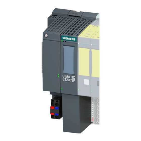
View of the module Figure 2-1 View of the IM 155-6 PN ST interface module and the server module Properties The module has the following technical properties: ● Connects the ET 200SP distributed I/O system with PROFINET IO ●... - Page 11 Group diagnostics: Missing supply voltage L+. When there are 32 I/O modules, the server module is inserted in slot 33. You can find more information in the Server module (http://support.automation.siemens.com/WW/view/en/63257531) manual. IM 155-6 PN ST interface module (6ES7155-6AU01-0BN0) Manual, 04/2017, A5E03576904-AE...
- Page 12 ● Configuration as of STEP 7 V5.5 SP4 with – HSP0241 V2.0 for IM155-6 PN ST – HSP0242 V2.0 for IM155-6 DP HF – HSP0255 V3.0 for IM155-6 PN HF ● Configuration as of STEP 7 V13 SP1 IM 155-6 PN ST interface module (6ES7155-6AU01-0BN0) Manual, 04/2017, A5E03576904-AE...
-
Page 13: Functions
● Station extension via ET-Connection ● The BusAdapter provides the connection system for PROFINET IO. The following versions are available for the IM 155-6 PN ST interface module: – For standard RJ45 connector: BA 2×RJ45 – For direct connection of the bus cable: BA 2×FC The interface module supports additional functions: ●... - Page 14 V4.1 X (as of V5.5 X (as of V14 article number: 6ES7155- SP4, HSP241 HSP205) 6AU01-0BN0 Systems of third-party manufacturers: Depending on the range of functions of the third-party system IM 155-6 PN ST interface module (6ES7155-6AU01-0BN0) Manual, 04/2017, A5E03576904-AE...
- Page 15 ● As of STEP 7 V12, in the PROFINET with STEP 7 V13 (http://support.automation.siemens.com/WW/view/en/49948856) function manual ● As of STEP 7 V5.5, in the system manual PROFINET System Description (http://support.automation.siemens.com/WW/view/en/19292127) IM 155-6 PN ST interface module (6ES7155-6AU01-0BN0) Manual, 04/2017, A5E03576904-AE...
- Page 16 The device name from the BusAdapter is used and copied BusAdapter is used and copied to the interface module. to the interface module if this has a different device name. IM 155-6 PN ST interface module (6ES7155-6AU01-0BN0) Manual, 04/2017, A5E03576904-AE...
- Page 17 ● As of STEP 7 V5.5, in the system manual PROFINET System Description (http://support.automation.siemens.com/WW/view/en/19292127) Replacement of an IM 155-6 PN ST In a replacement scenario, any IO devices in operation must be reset to their as-delivered state via "Reset to factory settings" (see the system manual ET 200SP distributed I/O system (http://support.automation.siemens.com/WW/view/en/58649293)).
- Page 18 If you set up all controllers in one project, the same send clock is ensured. Set the same send clock for engineering in separate projects. Submodules The IM 155-6 PN ST interface module supports the division of I/O modules into up to 4 submodules. This allows parts of an I/O module to be separately configured and parameterized.
-
Page 19: Profienergy
● As of STEP 7 V12, in the function manual PROFINET with STEP 7 V13 (http://support.automation.siemens.com/WW/view/en/49948856) Value status The IM 155-6 PN ST interface module supports I/O modules with value status. Additional information on the value status can be found in the manuals for the I/O modules. 2.2.1... -
Page 20: Use Of Fail-Safe Modules
2.2 Functions 2.2.2 Use of fail-safe modules Properties The IM 155-6 PN ST interface module as of firmware V1.0.1 supports the use of fail-safe modules. Reference You can find more information in the ET 200SP distributed I/O system (http://support.automation.siemens.com/WW/view/en/58649293) system manual. -
Page 21: Wiring
24 V DC 24 V DC (for looping through) Ground Ground (for looping through) 1L+ and 2L+ as well as 1M and 2M are bridged internally. Maximum 10 A permitted. IM 155-6 PN ST interface module (6ES7155-6AU01-0BN0) Manual, 04/2017, A5E03576904-AE... - Page 22 Receive data + Ground Ground RD_N Receive data - Ground Ground Note PROFINET interface X1 Port 2 If autonegotiation is disabled, the RJ-45 socket (X1 Port 2) has the switch assignment (MDI- IM 155-6 PN ST interface module (6ES7155-6AU01-0BN0) Manual, 04/2017, A5E03576904-AE...
- Page 23 Transmit data - RD_N Receive data - Reference You can find more information on accessories and how to connect the interface module in the ET 200SP distributed I/O system (http://support.automation.siemens.com/WW/view/en/58649293) system manual. IM 155-6 PN ST interface module (6ES7155-6AU01-0BN0) Manual, 04/2017, A5E03576904-AE...
-
Page 24: Schematic Circuit Diagram
Wiring 3.2 Schematic circuit diagram Schematic circuit diagram The following figure shows a block diagram of the IM 155-6 PN ST interface module. ① Switch 24 V DC supply voltage ② ET 200SP backplane bus interface and Mass electronics ③... -
Page 25: Parameters/Address Space
Parameters/address space Parameters Parameters for IM 155-6 PN ST interface module The following table shows the parameters for the IM 155-6 PN ST interface module. Table 4- 1 Parameters for interface module IM 155-6 PN ST (GSD file) Parameters Value range... -
Page 26: Substitute Value Behavior
● Reset to factory settings ● Configuration control: The IM has not received a valid control data record 196 yet. ● Incorrectly configured module ● Module with incorrect parameter assignment IM 155-6 PN ST interface module (6ES7155-6AU01-0BN0) Manual, 04/2017, A5E03576904-AE... -
Page 27: Status Of The Supply Voltage L+ Of The I/O Modules
The "Status of the supply voltage L+ of the I/O modules" is configured on the server module as of IM 155-6 PN ST V1.1.x and GSD file 04/2013. The input data can then be read out on the server module. You will find the relevant description in the Server module (http://support.automation.siemens.com/WW/view/en/63257531) device manual. -
Page 28: Interrupts, Diagnostics, Error, And System Messages
LK2 (green) Figure 5-1 LED display on the interface module and BusAdapter Meaning of the LEDs The meaning of the status and error messages is described in the following tables. IM 155-6 PN ST interface module (6ES7155-6AU01-0BN0) Manual, 04/2017, A5E03576904-AE... - Page 29 Siemens Industry interface do not flash). Online Support. Replace the interface module. * PWR LED on (on the interface module): Check the backplane bus for a short circuit. IM 155-6 PN ST interface module (6ES7155-6AU01-0BN0) Manual, 04/2017, A5E03576904-AE...
- Page 30 ERROR (red) and MAINT (yellow) LEDs. The following configuration errors are indicated by the LEDs: ● More than one I/O module pulled ● Missing server module ● Interruptions or short circuit on the backplane bus IM 155-6 PN ST interface module (6ES7155-6AU01-0BN0) Manual, 04/2017, A5E03576904-AE...
- Page 31 5 The MAINT LED flashes at 1 Hz Display of ones digit (decimal) of the error loca- tion/error code 6 Repeat steps 1 to 5 until the cause of the error has been corrected. IM 155-6 PN ST interface module (6ES7155-6AU01-0BN0) Manual, 04/2017, A5E03576904-AE...
- Page 32 A short circuit in the backplane bus supply or the bus connection supply is indicated by the following LEDs: • PWR LED: On • RN-, ER and MT LED: Off IM 155-6 PN ST interface module (6ES7155-6AU01-0BN0) Manual, 04/2017, A5E03576904-AE...
-
Page 33: Interrupts
The CPU interrupts the user program and processes the diagnostics block OB 82. The interrupt triggering event is logged in the start information of OB 82. IM 155-6 PN ST interface module (6ES7155-6AU01-0BN0) Manual, 04/2017, A5E03576904-AE... -
Page 34: Triggering A Hardware Interrupt
If there is a swapping interrupt, the CPU interrupts user program execution and processes the process interrupt block OB 83. The result that triggered the interrupt is added to the start information of OB 83. IM 155-6 PN ST interface module (6ES7155-6AU01-0BN0) Manual, 04/2017, A5E03576904-AE... -
Page 35: Alarms
Additional information on the data records for PROFINET IO The structure of the diagnostic data records and programming examples are available in the programming manual From PROFIBUS DP to PROFINET IO (http://support.automation.siemens.com/WW/view/en/19289930) and in Example application (http://support.automation.siemens.com/WW/view/en/24000238). IM 155-6 PN ST interface module (6ES7155-6AU01-0BN0) Manual, 04/2017, A5E03576904-AE... -
Page 36: Maintenance Events
● Maintenance demanded - indicated for each port by a yellow wrench icon in the device view or in the hardware configuration. You can find more information in the STEP 7 online help. IM 155-6 PN ST interface module (6ES7155-6AU01-0BN0) Manual, 04/2017, A5E03576904-AE... -
Page 37: Channel Diagnostics
You can purchase the standard from the PROFIBUS User Organization on the Internet (http://www.profibus.com). Coding of the extended channel diagnostics (as of firmware version V3.3.0) With the IM 155-6 PN ST interface module, the following extended channel diagnostics are reported: Slot number... - Page 38 Diagnostics with incorrect BaseUnit 0007 Diagnostics with incorrect bus configuration * As of IM 155-6 PN ST V1.1.x and GSD file 04/2013, this diagnostics is only signaled if the "Group diagnostics: Missing supply voltage L+" parameter has been activated. USI structure = W#16#0003...
- Page 39 • the IO controller. The number of pulled I/O modules follows Quantity W#16#0002 to Bit 8 to 15 W#16#0020 Bit 0 to 7 Followed by 2 reserved bytes: Reserved Reserved IM 155-6 PN ST interface module (6ES7155-6AU01-0BN0) Manual, 04/2017, A5E03576904-AE...
- Page 40 Bit 8 to 15 W#16#0040 Bit 0 to 7 If slot 0 is specified, check the width of the station configuration (maximum 1 m). Followed by 2 reserved bytes: Reserved Reserved IM 155-6 PN ST interface module (6ES7155-6AU01-0BN0) Manual, 04/2017, A5E03576904-AE...
-
Page 41: Invalid Configuration States Of The Et 200Sp On Profinet Io
● If an I/O module is removed during failure of the supply voltage, a pull alarm is generated. ● If an I/O module is installed during failure of the supply voltage, an insert alarm is generated. IM 155-6 PN ST interface module (6ES7155-6AU01-0BN0) Manual, 04/2017, A5E03576904-AE... -
Page 42: Stop Of The Io Controller And Recovery Of The Io Device
If you want to read the diagnostics of a station after its return, you have to read the E00C data record with the "RDREC" instruction in OB 86. This record contains all diagnostics for the slots assigned to an IO controller in an IO device. IM 155-6 PN ST interface module (6ES7155-6AU01-0BN0) Manual, 04/2017, A5E03576904-AE... -
Page 43: Compatibility
The table below describes which version you can use in the configuration for which actually plugged version of the IM 155-6 PN ST interface module. The table also describes the functional differences of the versions of the IM 155-6 PN ST interface module. - Page 44 The following maximum reaction time of the interface module must be taken into account when calculating the reaction times of fail-safe modules: maximum reaction time = configured update time + 400 μs (but at least 1.4 ms) IM 155-6 PN ST interface module (6ES7155-6AU01-0BN0) Manual, 04/2017, A5E03576904-AE...
-
Page 45: Technical Specifications
Technical specifications Technical specifications of the IM 155-6 PN ST Article number 6ES7155-6AU01-0BN0 General information Product type designation IM 155-6 PN ST with server module HW functional status FS01 Firmware version V4.1 Vendor identification (VendorID) 002AH Device identifier (DeviceID) 0313H Product function Yes;... - Page 46 PROFINET with 100 Mbit/s full duplex Transmission procedure • (100BASE-TX) Yes; for Ethernet services 10 Mbps • Yes; PROFINET with 100 Mbit/s full duplex 100 Mbps • (100BASE-TX) Autonegotiation • Autocrossing • IM 155-6 PN ST interface module (6ES7155-6AU01-0BN0) Manual, 04/2017, A5E03576904-AE...
- Page 47 Yes; 1500 V AC between supply and all other circuits Permissible potential difference between different circuits Safety extra low voltage SELV Isolation Isolation tested with 707 V DC (type test) IM 155-6 PN ST interface module (6ES7155-6AU01-0BN0) Manual, 04/2017, A5E03576904-AE...
- Page 48 Number of PROFINET interfaces RJ45 Yes; 2 x Cable length 100 m Copper cables • Dimensions Width 20 mm Height 69.5 mm Depth 59 mm Weights Weight, approx. 46 g IM 155-6 PN ST interface module (6ES7155-6AU01-0BN0) Manual, 04/2017, A5E03576904-AE...
- Page 49 Number of PROFINET interfaces FC (FastConnect) Yes; 2 x Cable length 100 m Copper cables • Dimensions Width 20 mm Height 69.5 mm Depth 59 mm Weights Weight, approx. 53 g IM 155-6 PN ST interface module (6ES7155-6AU01-0BN0) Manual, 04/2017, A5E03576904-AE...
-
Page 50: A Dimension Drawing
This appendix contains a dimension drawing of the module installed on a mounting rail. Always observe the specified dimensions for installation in cabinets, control rooms, etc. Figure A-1 Dimension drawing of the IM 155-6 PN ST interface module (front and side view) IM 155-6 PN ST interface module (6ES7155-6AU01-0BN0) Manual, 04/2017, A5E03576904-AE...