Advertisement
OUTSTANDING RECEPTION THE WORLD OVER
Notice: You can make use of the item " DISASSEMBLY" ,
regardless of the difference in appearance of the set,
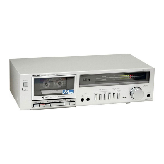
whose photographs are all those of Model RT-31H
(not RT-31 for SEC.)
Power source:
Power consumption:
Semi-conductors:
Dimensions: Width;
Height;
Depth;
Weight:
Tape:
Tape speed :
Wow & flutter:
Frequency response:
Normal tape;
Normal tape;
Photograph of RT-31 H
AC 11 OV/22OV/24OV, 50160 Hz
(RT-31 H/HB)
AC 12OV, 50/60 Hz (RT-31)
12 wattes (RT-31 H/HB)
7 ICs (Integrated Circuits)
12 Transistors
9 Diodes
6 LEDs (Light Emitting Diodes)
430 mm (16-15116" )
1 15.5 mm (4-9/l 6" )
237 mm (9-5/l 6" )
3.9 kg (8.6 Ibs) (RT-31 H/HB)
3.7 kg (8.2 Ibs) (RT-31)
Philips standard compact cassette
tape
4.8 cm/set. ( l-7/8 ips.)
0.19% (DIN 45 500)
0.06% (W.R.M.S.) (RT-31 H/HB)
0.065% (W.R.M.S.) (RT-31)
40 - 12,500 Hz (DIN 45 500)
30 - 14,000 Hz
Noise reduction system manufactured under license
f r o m D o l b y L a b o r a t o r i e s L i c e n s i n g C o r p o r a t i o n .
"Dolby" and the double-D symbol are trademarks of
Dolby Laboratories Licensing Corporation.
In the interests of user-safety the set should be
restored to its original condition and only parts
identical to those specified by used.
MAXELL UDXLII tape;
40 - 13,000 Hz 2 3 dB
MAXELL UDXLII tape;
30 - 15,000 Hz
40 - 13,009 Hz f 3 dB
TDK Metal tape;
40 - 16,000 Hz (DIN 45 500)
40 - 14,000 Hz f 3 dB
(RT-31 H/HB)
SONY Fe-Cr tape;
40 - 14,000 Hz (DIN 45 500)
40 - 13,000 Hz + 3 dB
S/N ratio (MAXELL UDXLII tape):
Dolby NR off;
56 dB
Dolby NR on;
66 dB (at over 5 kHz)
Input sensitivity and input impedance:
Microphones;
0.2 mV (6.8K ohms)
Line in;
50 mV (50K ohms)
DIN input;
0.2 mV (6.8K ohms) (RT-31 H/HB)
Output level and loaded impedance:
Headphones;
46 mV (" 0" dB) , 8 ohms
Line out;
550 mV (" 0" dB), 50K ohms
DIN output;
550 mV (" 0" dB), 50K ohms
Specifications are subject to change without prior notice.
(RT-31 H/HB)
Advertisement
Table of Contents

Related Manuals for Sharp RT-31


Summary of Contents for Sharp RT-31
- Page 1 S/N ratio (MAXELL UDXLII tape): Depth; 237 mm (9-5/l 6” ) Dolby NR off; 56 dB Weight: 3.9 kg (8.6 Ibs) (RT-31 H/HB) Dolby NR on; 66 dB (at over 5 kHz) 3.7 kg (8.2 Ibs) (RT-31) Input sensitivity and input impedance: Tape: Philips standard compact cassette Microphones;...
-
Page 2: Removal Of Front Panel
(Photographs of RT-31H) Prior to the disassembly, be sure to remove the AC supply cord from a wall outlet and the input/output plugs from the rear of the set. Take out a cassette tape, if loaded in the cassette compartment, From the cabinet, remove four screws two each at its right and left sides, and one screw at its rear surface. -
Page 3: Voltage Selection
Figure 3-4 CAUTION (RT-31 H/HB) If any one of the nylon bands shown in the Figure 3-5 is once removed for some reason, be sure to reprise it to the original place in the same appearance as before. -
Page 4: Mechanical Adjustment
PINCH ROLLER PRESSURE ADJUSTMENT (See Figure 4-l and 4-2) 2. Use a tension gauge (0 - 500 gr.) to push it to a part the capstan. Next gradually weaken the force in the reverse direction until the pinch roller hits the capstan (that is, it begins rotating), then see that tension gauge is reading 295 to 365 grams. -
Page 5: Electrical Adjustment
CY ADJUSTMENT OF RECORD AMPLIFIER (See Figure 5-l) * SW7 is not used for model RT-31. Posit ion Switch Indicated value Push SW4 normal 37 mV 2. Connect the vertical input terminal of oscilloscope to the VTVM and its horizontal input terminal to CR... - Page 6 (See Figure 6-l ) 1. Connect VTVM between test point TP103 (or TP203) and ground. 2. Push the tape selector switch SW4 and set the Dolby 3. Put a test tape (TEAC, MTT-150,400 Hz, 200 pWb/mm, recorded) into the unit and play it. 4.
-
Page 7: Alignment Points
4. Put a normal tape into the unit and place it in record 6. Give the set the signal of oscillation frequency 100 Hz, mode. Adjust the record level control VRI 02 (or output level -50 dB (0 dB = 1 Vi, then adjust the record level control VR102 (or VR202) so that VTVM will 5. - Page 8 MARKING SIDE 0 7 0 2 2SD794P NOTES: are subject to change for improvement without prior notice.) (Specifications or wiring diagrams of this model Figure 9 SCHEMATIC c...
- Page 9 2. Capacitor: 1. Resistor: To differentiate the units of resistors, such To indicate the unit of capacitor, a symbol P used; this symbol P means micro-microfar: symbols as K and M are used; the symbol K set. Be sure to replace these parts with means 1000 ohm and the symbol M m e a n s and the unit of the capacitor without sur specified ones for main taining the...
- Page 10 Figure 11 WIRING SIDE OF PRINT...
- Page 11 - ------~ - 1 2 -...
- Page 12 MARKING SIDE a70 I NOTES: Pa (Specifications or wiring diagrams of this model are subject to change for improvement without prior notice.) Figure 13 SCHEMATIC DIL...
- Page 13 I ,’ 2. Capacitor: 1. Resistor: ‘ ES: Parts marked with “ A” (0) are im- To indicate the unit of capacitor, a symbol P i: To differentiate the units of resistors, such used; this symbol P means micro-microfarao symbols as K and M are used; the symbol K set.
- Page 14 ------- --------- Figure 15 WIRING SIDE OF PRI...
- Page 15 LEFT...
- Page 16 BOTTOM Figure 17 MECHANISM EXPLODED VIEW...
- Page 17 Figure 18 CABINET EXPLODED VIEW (Use of RTSlH/HB)
-
Page 18: Replacement Parts List
As to Transistors, Diodes, Zener Diode and LED described in this parts list, they are different according to the Model RT- A distinction is drawn between the abovedescribed items by description of the used units parenthesized. 3 1 H/HE or RT-31, NOTES: Parts marked with “... -
Page 19: Top View
TOP VIEW D O L B Y B - T Y P E ’ N / C ‘ OWE R CIRCUIT Figure 20-I BLOCK DIAGRAM FRONT VIEW Figure 20-2 BLOCK DIAGRAM TOP VIEW Figure 20-3 BLOCK DIAGRAM FRONT VIEW Figure 20-4 EQUIVALENT CIRCUIT... - Page 20 Figure 19 CABINET EXPLODED VIEW (Use of RT-31)
- Page 21 P A R T S L I S T REF. NO. PART NO. DESCRIPTION REF. NO. DESCRIPTION PART NO. CODE TRANSFORMER CAPACITORS Power (RT-31 H/HB) AT501 Ceramic FILTERS Cl 16,216 Dolby, (Low Pass Filter) Semiconductor CONTROLS Cl 20,220 Cl 22,222...
- Page 22 (Normal) SW5; Tape Selector (CrOz 1 SW7; Tape Selector (Fe-01 A 2 3 6 AC Sypply Cord AC Suppry Cord Switch, Power (RT-31 H/HB) AE Switch, Power CRT-311 Switch, Muting Lug Terminal, (13mm) Switch, APSS Switch, Bias Lug Terminal, (17mm)
- Page 23 (RT-31/H) Spring, P.A.D. Gear Scale Plate, Cassette Cornpart- AC Spring, Dumper Lever ment lRT-31 HB) Spring (Plate type), Sub Front Panel (RT-31 H) Chassis Retaining 21 1 HPN LC3476AFSB Front Panel (RT-31 HB) Spring, (Plate type), Cassette Front Panel (RT-31)
-
Page 24: Mechanical Parts
22K ohm Button, Play/Fast-forward/ Rewind/Pause (RT-31/H) 6 8 o h m ll4W *5% Oxide Button, Play/Fast-forward/ Rewind/Pause iRT-31 HB) F i l m (RT-31 H/HBI 68 ohm (RT-31) Button Block Assembly Bracket, Control Button Arm, APSS Prevention Lever, APSS Prevention... -
Page 25: Parts List
(201) 265-5600 20600 S. Alameda St. Carson, 90810 (213) 637-9488 430 E. Plainfield Rd. Countryside, Illinois 60525 U.S. Subsrdiary of Sharp Corporation, Osaka, Japan Parts Centers: P.O. Box 664 Paramus, New Jersey 07652 P.O. Box 20394 Long Beach, 9080 1...