Table of Contents
Advertisement
User Guide OI/FET200–EN Rev. I
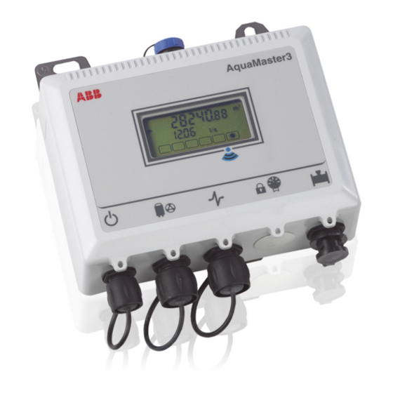
AquaMaster 3 FET200
Electromagnetic flowmeter
Transmitter
The smart solution for
remote applications
Introduction
TM
AquaMaster 3
is a range of high performance
electromagnetic flowmeters for the measurement of
electrically-conductive fluids and is normally supplied as
factory-configured, calibrated systems.
This User Guide provides end-user details for
AquaMaster 3 close-coupled and remote transmitters.
When the meter is taken out of storage and installed for
first use, remove the protective label (if fitted) from the
front to enable light to activate the unit.
If the meter is not powered, connect any batteries or
external supply as detailed in this manual.
For a comprehensive overview of publications available
for the AquaMaster 3 transmitter, refer to the inside
cover of this publication. Web links, QR code and
reference numbers are also included.
Advertisement
Table of Contents

Related Manuals for ABB AquaMaster 3 FET200


Summary of Contents for ABB AquaMaster 3 FET200
- Page 1 User Guide OI/FET200–EN Rev. I AquaMaster 3 FET200 Electromagnetic flowmeter Transmitter The smart solution for remote applications Introduction AquaMaster 3 is a range of high performance For a comprehensive overview of publications available electromagnetic flowmeters for the measurement of for the AquaMaster 3 transmitter, refer to the inside electrically-conductive fluids and is normally supplied as cover of this publication.
-
Page 2: For More Information
We are an established world force in the design and manufacture of instrumentation for industrial process control, flow measurement, gas and liquid analysis and environmental applications. As a part of ABB, a world leader in process automation technology, we offer customers application expertise, service and support worldwide. -
Page 3: Table Of Contents
AquaMaster 3 FET200 Electromagnetic flowmeter Transmitter Contents Contents Safety ............................... 3 Electrical Safety ............................. 3 Symbols ................................ 3 Health & Safety ............................. 4 Mechanical Installation ........................5 Installation Conditions ........................... 5 Fitting the Vandal-Resistant Housing (Integral Transmitters Only) ..............7 Dimensions .............................. - Page 4 AquaMaster 3 FET200 Electromagnetic flowmeter Transmitter Contents Start-Up and Operation ......................... 29 Start-up ............................... 29 Display Activation ............................30 Display Information ............................30 Servicing Plugs and Sockets ........................30 4.4.1 Service Intervals ..........................30 4.4.2 Equipment Required ........................31 4.4.3 Preparation ...........................
-
Page 5: Safety
AquaMaster 3 FET200 Electromagnetic flowmeter Transmitter 1 Safety 1 Safety Information in this manual is intended only to assist our customers in the efficient operation of our equipment. Use of this manual for any other purpose is specifically prohibited and its contents are not to be reproduced in full or part without prior approval of the Technical Publications Department. -
Page 6: Health & Safety
AquaMaster 3 FET200 Electromagnetic flowmeter Transmitter 1 Safety 1.3 Health & Safety Health and Safety To ensure that our products are safe and without risk to health, the following points must be noted: The relevant sections of these instructions must be read carefully before proceeding. -
Page 7: Mechanical Installation
AquaMaster 3 FET200 Electromagnetic flowmeter Transmitter 2 Mechanical Installation 2 Mechanical Installation 2.1 Installation Conditions Close-coupled version – allow room to read data plate Fig. 2.1 Siting 60 °C –20 °C (140 °F) AquaMaster 3 (–4 °F) Maximum Minimum Fig. 2.2 Within Temperature Limits Fig. - Page 8 AquaMaster 3 FET200 Electromagnetic flowmeter Transmitter 2 Mechanical Installation <2 m 78 in.) AquaMaster 3 Submerged – 9 Months Accrued Time IP68 (NEMA 6P) ENCLOSURE 6P Not applicable to GSM Integral Aerial Installations – see Section 2.4.1, page 10 Fig. 2.6 Within Environmental Rating...
-
Page 9: Fitting The Vandal-Resistant Housing (Integral Transmitters Only)
AquaMaster 3 FET200 Electromagnetic flowmeter Transmitter 2 Mechanical Installation 2.2 Fitting the Vandal-Resistant Housing (Integral Transmitters Only) Referring to Fig. 2.9: 1. Slide cover over transmitter. 2. Insert bottom plate ensuring clips enter lugs 3. Secure with lock Fig. 2.9 Fitting Anti-Vandal Housing... -
Page 10: Dimensions
AquaMaster 3 FET200 Electromagnetic flowmeter Transmitter 2 Mechanical Installation 2.3 Dimensions 2.3.1 Remote- and Close-Coupled Transmitter Dimensions in mm (in.) 125 (5.0) 115 (4.50) (2.0) Ø 6.5 (0.25) 28 (1.1) Ø13 (0.50) AquaMaster 3 (5.4) 280 (11.0) with (7.3) Connectors 177 (7.0) -
Page 11: Integral Transmitter And Vandal-Resistant Housing
AquaMaster 3 FET200 Electromagnetic flowmeter Transmitter 2 Mechanical Installation 2.3.2 Integral Transmitter and Vandal-Resistant Housing Dimensions in mm (in.) 244 (9.6) 175 (6.9) 220 (8.7) AquaMaster 3 Fig. 2.11 Integral Transmitter Dimensions Dimensions in mm (in.) 184 (7.2) 260 (10.2) Fig. -
Page 12: Gsm-Equipped Transmitters
AquaMaster 3 FET200 Electromagnetic flowmeter Transmitter 2 Mechanical Installation 2.4 GSM-Equipped Transmitters 2.4.1 GSM Antenna Installation Before deciding on an antenna mounting location, check that the local signal strength for the chosen mobile phone network is satisfactory. Use the GSM-equipped transmitter's integral signal strength test facility to establish signal strength. - Page 13 AquaMaster 3 FET200 Electromagnetic flowmeter Transmitter 2 Mechanical Installation Remote Antenna Integral Antenna 50 mm (2.0 in.) 50 mm (2.0 in.) AquaMaster 3 AquaMaster 3 Fig. 2.14 GSM Antenna Installation >50 mm (2.0 in.) Fig. 2.15 GSM Antenna Installation OI/FET200–EN Rev. I...
-
Page 14: Connecting A Remote Antenna
AquaMaster 3 FET200 Electromagnetic flowmeter Transmitter 2 Mechanical Installation 2.4.2 Connecting a Remote Antenna Referring to Fig. 2.16: 1. Remove the cover from the socket on top of the transmitter. 2. Gently push the antenna plug into the socket, then twist the screw ring clockwise until locked. - Page 15 AquaMaster 3 FET200 Electromagnetic flowmeter Transmitter 2 Mechanical Installation 7. Slide SIM card into holder , contact side down and bevelled edge to the top-right. 8. Close holder until it clicks into place and refit cover 9. Screw cover firmly in place.
-
Page 16: Electrical Installation
AquaMaster 3 FET200 Electromagnetic flowmeter Transmitter 3 Electrical Installation 3 Electrical Installation 3.1 Grounding Note. The grounding arrangements shown in Figs 3.1 to 3.3 are applicable to both cathodic and non-cathodic protected installations. Battery (Shown) or AquaMaster 3 Mains Power Supply Earth (Ground) Rod Fig. - Page 17 AquaMaster 3 FET200 Electromagnetic flowmeter Transmitter 3 Electrical Installation Battery (Shown) or Mains Power Supply AquaMaster 3 Earth (Ground) Rod Probe Sensor Ground Bond Probe to Pipe Fig. 3.3 AquaMaster3 Transmitter Mounted in a Cabinet – Probe Sensor OI/FET200–EN Rev. I...
-
Page 18: Connections
AquaMaster 3 FET200 Electromagnetic flowmeter Transmitter 3 Electrical Installation 3.2 Connections Note. Refer to Section Fig. 3.4, page 22 for MODBUS connection. 3.2.1 AquaMaster3 Sensor Connections (Remote or Close-Coupled only) Referring to Fig. 3.4: 1. Remove the screwed cap on the sensor connector. -
Page 19: Input / Output Connections
AquaMaster 3 FET200 Electromagnetic flowmeter Transmitter 3 Electrical Installation 3.3 Input / Output Connections Caution. Refer to the Specification, Section 5, page 34 for input / output ratings. Inductive loads must be suppressed or clamped to limit voltage swings. -
Page 20: Input / Output Connections
AquaMaster 3 FET200 Electromagnetic flowmeter Transmitter 3 Electrical Installation 3.3.3 Input / Output Connections Pin View Socket only WABC 2010 Fig. 3.8 Input / Output Connectons Color Signal Function (Output Cable) Not used Not used Violet DATA ScanReader Data Blue... -
Page 21: Scanreader Interface (Option)
AquaMaster 3 FET200 Electromagnetic flowmeter Transmitter 3 Electrical Installation 3.3.4 ScanReader Interface (Option) Reading Black Part No. WABC2104 /05, /10, /20, /30/ xx = cable length Cable Colors Green Data 3-Wire Transponder Connection Black Fig. 3.9 ScanReader Connections 3.3.5 RS232 Local Computer Connection... -
Page 22: Pressure Transducer (Optional)
AquaMaster 3 FET200 Electromagnetic flowmeter Transmitter 3 Electrical Installation 3.3.6 Pressure Transducer (Optional) Optional pressure transducer cables are available for a range of pressures and cable lengths. Fig. 3.11 Optional Pressure Transducer Connector Caution. Use only the pressure transducer supplied with the transmitter. Use of other pressure transducers requires alteration of the pressure span and zero factors in the transmitter. - Page 23 E & F* or fit adapters below Pressure socket If a pressure transducer is required, an adapter cable *ABB supply a plug with this link fitted – (part number WEBC2025) can be used part number WEBC2054 (Pack of 5) Fig.
-
Page 24: Modbus Connection
AquaMaster 3 FET200 Electromagnetic flowmeter Transmitter 3 Electrical Installation 3.4 MODBUS Connection This section describes the AquaMaster3 MODBUS serial data communications option and must be used in conjunction with: MODBUS Tables Supplement (COI/FET2XX/MOD/TBL–EN) Programming Guide (COI/FET2XX–EN) Detailed specifications and recommendations for using and implementing MODBUS communications are contained in the following external publications: ... -
Page 25: 2-Wire Connection
AquaMaster 3 FET200 Electromagnetic flowmeter Transmitter 3 Electrical Installation 3.4.1 2-wire Connection AquaMaster3 MODBUS RS485 uses a 2-wire serial link in accordance with EIA/TIA-485 standard – see Fig. 3.14. Master Line Pull Up Terminator Balanced Pair Line Terminator Pull Down... -
Page 26: Termination Resistor
AquaMaster 3 FET200 Electromagnetic flowmeter Transmitter 3 Electrical Installation 3.4.4 Termination Resistor To minimize transmission line travelling wave reflections caused by impedance discontinuities at the end of the described RS485-cable a Line Termination is required near each of the 2 ends of the 'Bus' as described in the MODBUS over Serial Line –... -
Page 27: Power Supply Connections
AquaMaster 3 FET200 Electromagnetic flowmeter Transmitter 3 Electrical Installation 3.5 Power Supply Connections AquaMaster3 has 4 power supply options: Internal batteries (integral transmitters only) – see Section 3.5.1 (following) External battery pack – see Section 3.5.2, page 27 ... - Page 28 AquaMaster 3 FET200 Electromagnetic flowmeter Transmitter 3 Electrical Installation – – Fig. 3.17 Internal Battery Pack (Integral Transmitters Only) OI/FET200–EN Rev. I...
-
Page 29: External Battery Power Supply
AquaMaster 3 FET200 Electromagnetic flowmeter Transmitter 3 Electrical Installation 3.5.2 External Battery Power Supply Note. Before making connections, check the Data label to confirm power supply requirements. AquaMaster3 can be powered from Explorer-style battery packs fitted with the MIL plastic style plug. -
Page 30: Renewable Energy Supply
For these reasons, in some installations, generators with a capacity greater then the specified 5 W minimum should be used. Contact ABB for a technical note, giving guidance on the selection of suitably sized generators for AquaMaster3. -
Page 31: Start-Up And Operation
The battery pack used by AquaMaster3 may present a risk of fire or chemical burns if mistreated. Do not recharge, disassemble, heat above 100 °C (212 °F) or incinerate. Replace battery pack with an ABB-supplied part only. Use of another battery may present a risk of fire or explosion. ... -
Page 32: Display Activation
Renewable Energy Not Present Fig. 4.1 AquaMaster3 Display Information 4.4 Servicing Plugs and Sockets To ensure long and reliable service life for the plugs and sockets on AquaMaster3 Flow Transmitters, ABB recommend regular treatment of the gold connector pins. Connectors Fig. -
Page 33: Equipment Required
AquaMaster 3 FET200 Electromagnetic flowmeter Transmitter 4 Start-Up and Operation 4.4.2 Equipment Required Cleaners are available from your local ABB representative. To purchase supplies directly or for local distributor details please go to the following website: http://store.caig.com/ Material details are: Description Part No. -
Page 34: Order Of Treatment
AquaMaster 3 FET200 Electromagnetic flowmeter Transmitter 4 Start-Up and Operation 4.4.5 Order of Treatment To minimize disruptive effects of repeatedly breaking and making connections perform the following order of treatment using the Stage 1 and Stage 2 processes for each plug and socket in turn: 1. -
Page 35: Stage 2 - Oxide Prevention
AquaMaster 3 FET200 Electromagnetic flowmeter Transmitter 4 Start-Up and Operation 4.4.7 Stage 2 – Oxide Prevention To prevent oxide build-up: 1. Apply a very short burst (not more than 0.5 seconds duration) of DeoxIT Gold GN5 spray to the metal surfaces. -
Page 36: Specification
Stainless steel housing in a thermoplastic outer cover with window, encapsulated with polyurethane-based resin. Electrical connections IP68 plug and socket, mains cable Sensor cable ABB cable supplied as standard SWA cable available (via adaptor box) on application Mains supply 85 to 265 V AC @ <3 VA Connection cable: approx. - Page 37 AquaMaster 3 FET200 Electromagnetic flowmeter Transmitter 5 Specification External battery pack IP68 (NEMA 6P) Manganese alkaline battery life @ 0 to 45 °C (32 to 113 °F): Nominal 5 years (standard) / 10 years (optional) operation * Lithium battery pack with 10-year life (optional)
- Page 38 – 2-wire for inductive pads (max. cable length 80 m [260 ft]) – 3-wire for AMR Compatible readers – Severn Trent Services Smart reader – ABB or Elster SR100 and SR50 – Logicon Versaprobe – Itron ERT Compatible inductive pads –...
- Page 39 AquaMaster 3 FET200 Electromagnetic flowmeter Transmitter 5 Specification Temperature ranges Storage Ambient 70 °C (158 °F) 60 °C (140 °F) –10 °C (14 °F) –20 °C (–4 °F) Battery capacity and life are shortened when operating outside the temperature range: Manganese Alkaline 0 to 45 °C (32 to 113 °F)
- Page 40 7 days (approx.) @ 1 minutes 2 years Software availability Software Direct RS232 SMS (Text) ABB AC800M ABB Generic (for example, LogMaster) Areal (Topkapi) MasterVue (I&P AutoChart) EcoTech ...
-
Page 41: Appendix A - Gsm-Equipped Units, Safety Precautions
AquaMaster 3 FET200 Electromagnetic flowmeter Transmitter Appendix A – GSM-Equipped Units, Safety Precautions Appendix A – GSM-Equipped Units, Safety Precautions The following safety precautions must be observed during all phases of the operation, usage, service or repair of this GSM cellular terminal. Failure to comply with these precautions violates safety standards of design, manufacture and intended use of the product. -
Page 42: Appendix B Accessories / Spares Kits
AquaMaster 3 FET200 Electromagnetic flowmeter Transmitter Appendix B Accessories / Spares Kits Appendix B Accessories / Spares Kits B.1 Common accessories MRBX9969 Close-coupled mounting kit WEBC2003/10 Remote GSM aerial kit 10 m (32 ft.) AquaMaster 3 Remote GSM quad band aerial kit: WEBC2110/01 1m (3.3 ft.) - Page 43 Repair Centre. — Metals and Minerals — Oil, Gas & Petrochemical — Pulp and Paper ABB Limited Tel: +44 (0)1453 826661 Drives and Motors Fax: +44 (0)1453 829671 — AC and 6 Drives, AC and DC Machines, AC Motors to —...
- Page 44 Oldends Lane document without prior notice. With regard to Stonehouse purchase orders, the agreed particulars shall prevail. ABB does not accept any responsibility Gloucestershire GL10 3TA whatsoever for potential errors or possible lack of information in this document. Tel:...