HP proliant DL380 GEN9 User Manual
Hide thumbs
Also See for proliant DL380 GEN9:
- User manual (167 pages) ,
- Maintenance and service manual (142 pages) ,
- Maintenance and service manual (119 pages)
Table of Contents
Advertisement
Quick Links
HPE ProLiant DL380 Gen9 Server
User Guide
Abstract
This document is for the person who installs, administers, and troubleshoots servers and storage systems. Hewlett Packard Enterprise
assumes you are qualified in the servicing of computer equipment and trained in recognizing hazards in products with hazardous energy
levels.
Part Number: 768830-007
November 2016
Edition: 7
Advertisement
Table of Contents

Related Manuals for HP proliant DL380 GEN9


Summary of Contents for HP proliant DL380 GEN9
-
Page 1: User Guide
HPE ProLiant DL380 Gen9 Server User Guide Abstract This document is for the person who installs, administers, and troubleshoots servers and storage systems. Hewlett Packard Enterprise assumes you are qualified in the servicing of computer equipment and trained in recognizing hazards in products with hazardous energy levels. - Page 2 © Copyright 2014, 2016 Hewlett Packard Enterprise Development LP The information contained herein is subject to change without notice. The only warranties for Hewlett Packard Enterprise products and services are set forth in the express warranty statements accompanying such products and services. Nothing herein should be construed as constituting an additional warranty.
-
Page 3: Table Of Contents
Contents Component identification .......................... 7 Front panel components ............................7 Front panel LEDs and buttons ..........................9 UID button functionality ..........................10 Power fault LEDs ............................11 Access the optional HPE Systems Insight Display ....................11 Systems Insight Display LEDs ..........................12 Systems Insight Display LED combinations ...................... - Page 4 750 W Flex Slot Hot Plug Battery Backup Module ....................134 Flex slot battery backup module configuration load support ..............134 Installing the FSBBU ..........................135 HP Trusted Platform Module option ........................136 Installing the Trusted Platform Module board .................... 137 Retaining the recovery key/password......................138 Enabling the Trusted Platform Module ......................
- Page 5 Eight-bay SFF front drive cage cabling ........................ 146 Express Bay Enablement Option cabling options ....................151 8SFF drive cage installed in bay 1 ......................152 8SFF drive cage installed in bay 1 and 2SFF drives in the rear of the server ........... 153 Drive bay 1 is empty ..........................
- Page 6 Belarus Kazakhstan Russia marking ......................190 Turkey RoHS material content declaration ....................191 Ukraine RoHS material content declaration ....................191 Specifications ............................192 Environmental specifications ..........................192 Mechanical specifications ............................. 192 Power supply specifications ..........................193 HPE 500W Flex Slot Platinum Hot-plug Power Supply ................194 HPE 800W Flex Slot Platinum Hot-plug Power Supply ................
-
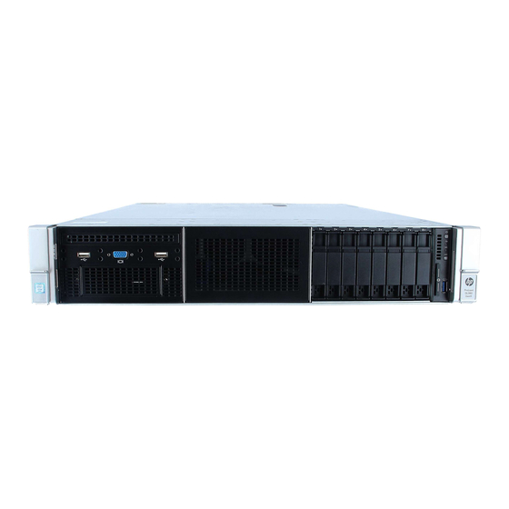
Page 7: Component Identification
Component identification Front panel components • SFF model (8-drive) Item Description Bay 1 (optional drives or universal media bay) Bay 2 (optional drives) Fixed drive bays Front USB 3.0 connector Serial label pull tab • SFF model (24-drive) Item Description Bay 1 Bay 2 Bay 3, fixed drive bay... - Page 8 • LFF model (12-drive) Item Description Drive bays 1-12 • LFF model (4-drive) Item Description Drive bays Component identification 8...
-
Page 9: Front Panel Leds And Buttons
Front panel LEDs and buttons • SFF front panel LEDs and button Item Description Status Power On/Standby button Solid green = System on and system power LED* Flashing green (1 Hz/cycle per sec) = Performing power on sequence Solid amber = System in standby Off = No power present** Health LED* Solid green = Normal... -
Page 10: Uid Button Functionality
• LFF LEDs and button Item Description Status Health LED* Solid green = Normal Flashing green (1 Hz/cycle per sec) = iLO is rebooting Flashing amber = System degraded Flashing red (1 Hz/cycle per sec) = System critical** Power On/Standby button Solid green = System on and system power LED* Flashing green (1 Hz/cycle per sec) = Performing power on... -
Page 11: Power Fault Leds
Power fault LEDs The following table provides a list of power fault LEDs, and the subsystems that are affected. Not all power faults are used by all servers. Subsystem LED behavior 1 flash System board 2 flashes Processor 3 flashes Memory 4 flashes Riser board PCIe slots... -
Page 12: Systems Insight Display Leds
Systems Insight Display LEDs The Systems Insight Display LEDs represent the system board layout. The display enables diagnosis with the access panel installed. Item Description Status Power supplies Off = Normal Solid amber = Power subsystem degraded, power supply failure, or input power lost. -
Page 13: Systems Insight Display Led Combinations
Systems Insight Display LED combinations When the health LED on the front panel illuminates either amber or red, the server is experiencing a health event. Combinations of illuminated Systems Insight Display LEDs, the system power LED, and the health LED indicate system status. Systems Insight Health LED System power... -
Page 14: Rear Panel Components
Rear panel components Item Description PCIe slots 1–3 (top to bottom) Optional PCIe slots 4–6 (top to bottom)* Optional serial port Power supply 1 (PS1) Power supply 2 (PS2) Video connector 1Gb RJ-45 port 4 1Gb RJ-45 port 3 1Gb RJ-45 port 2 1Gb RJ-45 port 1 iLO connector USB 3.0 connectors... -
Page 15: Flex Slot Battery Backup Module Leds And Buttons
Item Description Status Solid green = Link to network Flashing green = Network activity Power supply 2 Off = System is off or power supply has failed. Solid green = Normal Power supply 1 Off = System is off or power supply has failed. Solid green = Normal Flex slot battery backup module LEDs and buttons Item... -
Page 16: System Board Components
Mode/State Auxiliary path A/B protection Flashing red FSBBU fault or other protections Solid red For more information about the FSBBU module, see "750 W Flex Slot Hot Plug Battery Backup Module (on page 134)." System board components Item Description FlexibleLOM connector Primary (processor 1) PCI riser connector Optical front VGA/USB 2.0 connector x4 SATA port 1... -
Page 17: System Maintenance Switch
Item Description Dual internal USB 3.0 connector Smart Array/HBA connector Secondary processor (processor 2) PCI riser connector System battery TPM connector Optional serial port connector System maintenance switch System maintenance switch Position Default Function Off = iLO security is enabled. On = iLO security is disabled. -
Page 18: Dimm Slot Locations
To force the OS to invoke the NMI handler and generate a crash dump log, the administrator can use the iLO Virtual NMI feature. DIMM slot locations DIMM slots are numbered sequentially (1 through 12) for each processor. The supported AMP modes use the letter assignments for population guidelines. -
Page 19: Non-Hot-Plug Pci Riser Board Slot Definitions
Item LED definitions • Solid or flashing green = Power is available to the NVDIMM. Do not remove the NVDIMM. • Off = Power is not available to the NVDIMM. Non-hot-plug PCI riser board slot definitions • Primary riser cage connector, connected to processor 1 PCIe 3-slot riser cage* Optional PCIe 2-slot x16 riser cage PCIe3 x16 (8,4,2,1) -
Page 20: Sas And Sata Device Numbers
SAS and SATA device numbers • 8SFF device bay numbering • Optional 16SFF device bay numbering • Optional 16SFF device bay numbering with SAS expander solution used • Optional 24SFF device bay numbering Component identification 20... - Page 21 • Optional 24SFF device bay numbering with SAS expander solution used • 6SFF NVMe Express Bay Enablement Option device numbering with 8SFF drive cage installed in bay 1 • 6SFF NVMe Express Bay Enablement Option device numbering with 2SFF drive cage installed in universal media bay 1 •...
- Page 22 • 12LFF device bay numbering • 12LFF device bay numbering with 2-bay rear SAS expander solution used • 12LFF device bay numbering with 3-bay rear SAS expander solution used Component identification 22...
-
Page 23: Hot-Plug Drive Led Definitions
• 4LFF device bay numbering Hot-plug drive LED definitions Item Status Definition Locate Solid blue The drive is being identified by a host application. Flashing blue The drive carrier firmware is being updated or requires an update. Activity ring Rotating green Drive activity. -
Page 24: Nvme Ssd Components
NVMe SSD components The NVMe SSD is a PCIe bus device. A device attached to a PCIe bus cannot be removed without allowing the device and bus to complete and cease the signal/traffic flow. CAUTION: Do not remove an NVMe SSD from the drive bay while the Do Not Remove button LED is flashing. - Page 25 For a single-processor configuration, excluding 24-SFF and 12-LFF configurations, four fans and two blanks are required in specific fan bays for redundancy. A fan failure or missing fan causes a loss of redundancy. A second fan failure or missing fan causes an orderly shutdown of the server. For a dual-processor configuration or single-processor 24-SFF or 12-LFF configurations, six fans are required for redundancy.
-
Page 26: Operations
Operations Powering up the server To power up the server, press the Power On/Standby button. Power down the server Before powering down the server for any upgrade or maintenance procedures, perform a backup of critical server data and programs. IMPORTANT: When the server is in standby mode, auxiliary power is still being provided to the system. -
Page 27: Remove The Server From The Rack
Extend the server from the rack. After performing the installation or maintenance procedure, slide the server back into the rack, and then press the server firmly into the rack to secure it in place. WARNING: To reduce the risk of personal injury, be careful when pressing the server rail-release latches and sliding the server into the rack. -
Page 28: Install The Access Panel
Install the access panel Place the access panel on top of the server with the hood latch open. Allow the panel to extend past the rear of the server approximately 1.25 cm (0.5 in). Push down on the hood latch. The access panel slides to a closed position. Tighten the security screw on the hood latch. -
Page 29: Remove The Fan Cage
Open the cable management arm. The cable management arm can be right-mounted or left-mounted. Remove the fan cage To remove the component: Power down the server (on page 26). Remove all power: Disconnect each power cord from the power source. Disconnect each power cord from the server. -
Page 30: Remove The Hot-Plug Fan
CAUTION: Do not operate the server for long periods with the access panel open or removed. Operating the server in this manner results in improper airflow and improper cooling that can lead to thermal damage. IMPORTANT: For optimum cooling, install fans in all primary fan locations. For more information, refer to the fan locations table ("Hot-plug fans"... -
Page 31: Install The Pci Riser Cage
Remove the server from the rack (on page 27). Remove the access panel (on page 27). Remove the PCI riser cage. Install the PCI riser cage Power down the server (on page 26). Remove all power: Disconnect each power cord from the power source. Disconnect each power cord from the server. -
Page 32: Secure The Full-Length Expansion Board Retainer
Install the access panel (on page 28). Install the server into the rack ("Installing the server into the rack" on page 39). Connect each power cord to the server. Connect each power cord to the power source. Power up the server ("Powering up the server"... -
Page 33: Install The Air Baffle
Remove all power: Disconnect each power cord from the power source. Disconnect each power cord from the server. Extend the server from the rack (on page 26). Remove the access panel (on page 27). CAUTION: Do not detach the cable that connects the battery pack to the cache module. Detaching the cable causes any unsaved data in the cache module to be lost. - Page 34 Install the air baffle. Operations 34...
-
Page 35: Setup
Setup Optional services Delivered by experienced, certified engineers, HPE support services help you keep your servers up and running with support packages tailored specifically for HPE ProLiant systems. HPE support services let you integrate both hardware and software support into a single package. A number of service level options are available to meet your business and IT needs. -
Page 36: Temperature Requirements
• Side—The clearance between the installed rack component and the side panels of the rack must be a minimum of 7 cm (2.75 in). IMPORTANT: The HPE ProLiant DL380 Gen9 Server cable management arm is not supported on Compaq branded 7000 series racks. -
Page 37: Electrical Grounding Requirements
CAUTION: Protect the server from power fluctuations and temporary interruptions with a regulating uninterruptible power supply. This device protects the hardware from damage caused by power surges and voltage spikes and keeps the system in operation during a power failure. When installing more than one server, you may need to use additional power distribution devices to safely provide power to all devices. -
Page 38: Rack Warnings
CAUTION: If the DC connection exists between the earthed conductor of the DC supply circuit and the earthing conductor at the server equipment, the following conditions must be met: • This equipment must be connected directly to the DC supply system earthing electrode conductor or to a bonding jumper from an earthing terminal bar or bus to which the DC supply system earthing electrode conductor is connected. -
Page 39: Installing Hardware Options
• Server • Power cord • Hardware documentation and software products • Rack-mounting hardware and documentation In addition to the supplied items, you might need: • Operating system or application software • Hardware options • Screwdriver Installing hardware options Install any hardware options before initializing the server. For options installation information, refer to the option documentation. -
Page 40: Installing The Operating System
IMPORTANT: When using cable management arm components, be sure to leave enough slack in each of the cables to prevent damage to the cables when the server is extended from the rack. Connect the power cord to the AC power source. WARNING: To reduce the risk of electric shock or damage to the equipment: •... -
Page 41: Powering On And Selecting Boot Options In Uefi Boot Mode
During server POST, press F10. Complete the initial Preferences and Registration portion of Intelligent Provisioning (on page 176). At the 1 Start screen, click Configure and Install. To finish the installation, follow the onscreen prompts. An Internet connection is required to update the firmware and systems software. -
Page 42: Registering The Server
Registering the server To experience quicker service and more efficient support, register the product at the Hewlett Packard Enterprise Product Registration website (http://www.hpe.com/info/register). Setup 42... -
Page 43: Hardware Options Installation
Hardware options installation Hewlett Packard Enterprise product QuickSpecs For more information about product features, specifications, options, configurations, and compatibility, see the product QuickSpecs on the Hewlett Packard Enterprise website (http://www.hpe.com/info/qs). Introduction If more than one option is being installed, read the installation instructions for all the hardware options and identify similar steps to streamline the installation process. -
Page 44: Removing The Hard Drive Blank
Removing the hard drive blank Remove the component as indicated. Installing a hot-plug SAS or SATA drive To install the component: Remove the drive blank. Prepare the drive. Install the drive. Hardware options installation 44... -
Page 45: Removing A Hot-Plug Sas Or Sata Hard Drive
Determine the status of the drive from the drive LED definitions ("Hot-plug drive LED definitions" on page 23). Removing a hot-plug SAS or SATA hard drive CAUTION: For proper cooling, do not operate the server without the access panel, baffles, expansion slot covers, or blanks installed. -
Page 46: 6Sff Nvme Express Bay Drive Cage
Press the Do Not Remove button to open the release handle. Install the drives. Install an SFF drive blank in any unused drive bays. 6SFF NVMe Express Bay drive cage The high-performance fan option (part number 719079-B21) must be installed when installing this option. With the 6SFF NVMe Express bay Enablement option installed, the server supports SAS drives, SATA drives, SSDs, and NVMe drives in the following locations: •... -
Page 47: Installing The Airflow Labels
Installing the airflow labels When installing the HPE Express Bay drive cage in bay two, the airflow labels included in the kit must be installed depending on the option installed in bay one: • If the Eight-bay SFF Front Drive Cage option is installed in bay one, then no further action is required. -
Page 48: Installing The Express Bay Drive Cage
• If a blank is installed in bay one, then install the Drive bay 1 airflow label (814814-001) as indicated. Installing the Express Bay drive cage WARNING: To reduce the risk of personal injury from hot surfaces, allow the drives and the internal system components to cool before touching them. - Page 49 Remove the bay 2 blank. If drive blanks are installed in the drive cage assembly, remove the drive blanks ("Removing the hard drive blank" on page 44). Retain the drive blanks for use in empty drive bays. Install the HPE Express Bay drive cage. Connect the power cable depending on the server configuration.
- Page 50 8SFF drive cage installed in bay 1 — Use the 8SFF drive cage power cable (776399-001). Hardware options installation 50...
- Page 51 8SFF drive cage installed in bay 1 and 2 SFF drives in the rear of the server — Use the 8SFF drive cage power cable (776399-001) and the 2SFF drives-rear power cable (776400-001). Hardware options installation 51...
- Page 52 Drive bay 1 is empty — Use the NVMe power cable (776392-001). 8SFF drive cage installed in bay 1 and 2SFF drives in the front of the server — Use the 8SFF drive cage power cable (776399-001) and the 2SFF drives-front power cable (795156-001). Remove the primary PCI riser cage ("Remove the PCI riser cage"...
- Page 53 Remove the expansion slot blank from slot 2. Install the HPE Express Bay Bridge Card. Hardware options installation 53...
- Page 54 Using the cable trough and clips, connect the NVMe data cable (826898-001) to the HPE Express Bay Bridge Card. If the HPE 12G SAS Expander Card is installed, install the 12G SAS expander card cable (776402-001) (not shown). Install the drives ("Installing a hot-plug SAS or SATA drive"...
-
Page 55: Redundant Hot-Plug Power Supply Option
Install the fan cage. The fan cage should be populated with high-performance fans when installing the Express Bay Enablement option. Install the air baffle (on page 33). Install the access panel (on page 28). Do one of the following: Slide the server into the rack. Install the server into the rack. -
Page 56: High-Performance Fan Option
Insert the power supply into the power supply bay until it clicks into place. Connect the power cord to the power supply. Route the power cord. Use best practices when routing power cords and other cables. A cable management arm is available to help with routing. To obtain a cable management arm, contact a Hewlett Packard Enterprise authorized reseller. - Page 57 Remove the access panel (on page 27). IMPORTANT: Do not mix standard fans and high-performance fans in the same server. Remove fan blanks and standard fans from all locations: Fan blanks Standard fans Hardware options installation 57...
-
Page 58: Processor And Fan Option
Install high-performance fans in all locations. Install the access panel (on page 28). Slide the server into the rack. Connect each power cord to the server. Connect each power cord to the power source. Power up the server ("Powering up the server"... - Page 59 Open each of the processor locking levers in the order indicated in the following illustration, and then open the processor retaining bracket. Remove the clear processor socket cover. Retain the processor socket cover for future use. CAUTION: THE PINS ON THE SYSTEM BOARD ARE VERY FRAGILE AND EASILY DAMAGED.
- Page 60 Install the processor. Verify that the processor is fully seated in the processor retaining bracket by visually inspecting the processor installation guides on either side of the processor. THE PINS ON THE SYSTEM BOARD ARE VERY FRAGILE AND EASILY DAMAGED. Close the processor retaining bracket.
- Page 61 Press and hold the processor retaining bracket in place, and then close each processor locking lever. Press only in the area indicated on the processor retaining bracket. CAUTION: Close and hold down the processor cover socket while closing the processor locking levers.
- Page 62 Finish the installation by completely tightening the screws in the same sequence. Remove the fan blanks from locations 1 and 2. For fan location and numbering information, see "Hot-plug fans (on page 24)" or the label attached to the chassis next to the fans. Hardware options installation 62...
-
Page 63: Memory Options
Install the fans into locations 1 and 2. Install the air baffle (on page 33). Install the access panel (on page 28). Install the server into the rack. Connect each power cord to the server. Connect each power cord to the power source. Press the Power On/Standby button. -
Page 64: Memory-Processor Compatibility Information
Memory-processor compatibility information The processor installed in the server determines the type of DIMMs supported by the server. For the latest memory configuration information, see the following resources: • The product QuickSpecs on the Hewlett Packard Enterprise website (http://www.hpe.com/info/qs) • HPE Server Memory Configurator (https://h22195.www2.hpe.com/DDR4memoryconfig/Home/Legal) DIMM type... -
Page 65: Smartmemory
Populated DIMM speed — Intel Xeon E5-2600 v4 processor installed Type Rank Capacity 1 DIMM per 2 DIMMs per 3 DIMMs per (GB) channel (MT/s) channel (MT/s) channel (MT/s) Single 8 or 16 2400 2133 1866 RDIMM Single 2133 1866 1600 NVDIMM-N (RDIMM) -
Page 66: Memory Subsystem Architecture
Qualified memory is performance-tuned for ProLiant and BladeSystem servers and provides future enhanced support through Active Health and manageability software. Persistent memory combines the performance of memory with the persistence of traditional storage. NVDIMMs are DIMMs that provide persistent memory and install in standard DIMM slots. NVDIMM-Ns are NVDIMMs that combine DRAM with NAND flash memory, backing up the DRAM contents to flash memory on power loss and restoring from NAND flash memory to DRAM on power on. -
Page 67: Dimm Ranks
This multi-channel architecture provides enhanced performance in Advanced ECC mode. This architecture also enables Online Spare Memory mode. DIMM slots in this server are identified by number and by letter. Letters identify the population order. Slot numbers indicate the DIMM slot ID for spare replacement. DIMM ranks To understand and configure memory protection modes properly, an understanding of DIMM rank is helpful. -
Page 68: Memory Configurations
Item Description Definition 2R = Dual-rank 4R = Quad-rank 8R = Octal-rank Data width on DRAM x4 = 4-bit x8 = 8-bit Memory generation DDR4 Maximum memory speed 2400 MT/s CAS latency P=15 T=17 DIMM type R = RDIMM (registered) L = LRDIMM (load reduced) For more information about product features, specifications, options, configurations, and compatibility, see the product QuickSpecs on the Hewlett Packard Enterprise website (http://www.hpe.com/info/qs). -
Page 69: Maximum Capacity
To optimize server availability, the server supports the following AMP modes: • Advanced ECC—Provides up to 4-bit error correction. This mode is the default option for this server. • Online spare memory—Provides protection against failing or degraded DIMMs. Certain memory is reserved as spare, and automatic failover to spare memory occurs when the system detects a DIMM that is degrading. -
Page 70: General Dimm And Nvdimm-N Slot Population Guidelines
Mirrored memory configuration Mirroring provides protection against uncorrected memory errors that would otherwise result in server downtime. Mirroring is performed at the channel level to one memory channel pair that can be either: • Channel 1 data being mirrored in channel 2 •... -
Page 71: Identifying The Processor Type
• DIMMs may be installed individually. Online spare population guidelines For Online Spare memory mode configurations, observe the following guidelines: • Observe the general DIMM slot population guidelines. • Each channel must have a valid online spare configuration. • Each channel can have a different valid online spare configuration. •... -
Page 72: Dimm Handling Guidelines
CAUTION: Electrostatic discharge can damage electronic components. Be sure you are properly grounded before beginning this procedure. CAUTION: Failure to properly handle DIMMs can cause damage to DIMM components and the system board connector. Before installing memory on the server: •... -
Page 73: Installing A Dimm
Installing a DIMM The server supports up to 24 DIMMs. To install a DIMM: Power down the server (on page 26). Remove all power: Disconnect each power cord from the power source. Disconnect each power cord from the server. Do one of the following: Extend the server from the rack (on page 26). - Page 74 CAUTION: Unlike traditional storage devices, NVDIMMs are fully integrated in with the ProLiant server. Data loss can occur when system components, such as the processor or HPE Smart Storage Battery fails. HPE Smart Storage battery is a critical component required to perform the backup functionality of NVDIMM.
-
Page 75: Universal Media Bay Option
Universal media bay option The following procedure provides the steps to install the universal media bay option, route the VGA and USB cables, and install an optional optical disk drive. The universal media bay option also accommodates the two-bay SFF front drive cage option. For information on installing this option, see "Two-bay SFF front drive cage option (on page 99)."... - Page 76 Route the USB/VGA cables through the opening, and then install the universal media bay. Install the optional optical disk drive (optional). Connect the cables: Hardware options installation 76...
- Page 77 Connect the VGA cable to the optional VGA connector. Connect the USB cable to the front dual internal USB 3.0 connector. Connect the SATA optical drive cable to the front optical disk drive connector (optional). Install the fan cage. Install the air baffle (on page 33). Hardware options installation 77...
-
Page 78: 2-Slot Pci Riser Cage Option
Install the access panel (on page 28). Slide the server into the rack. Connect each power cord to the server. Connect each power cord to the power source. Power up the server ("Powering up the server" on page 26). 2-slot PCI riser cage option WARNING: To reduce the risk of personal injury, electric shock, or damage to the equipment, remove the power cord to remove power from the server. - Page 79 Remove the blank from the optional 2-slot PCI riser cage. Install an optional expansion board into the PCI riser cage. Install the optional 2-slot PCI riser cage. Connect any required internal or external cables to the expansion board. See the documentation that ships with the expansion board.
-
Page 80: 3-Slot Pci Riser Cage Option
Power up the server ("Powering up the server" on page 26). 3-slot PCI riser cage option WARNING: To reduce the risk of personal injury, electric shock, or damage to the equipment, remove the power cord to remove power from the server. Pressing the Power On/Standby button does not shut off system power completely. - Page 81 Remove the blank from the optional 3-slot PCI riser cage. Install an expansion board into the PCI riser cage. Install the optional 3-slot PCI riser cage. Install the access panel (on page 28). Slide the server into the rack. Connect each power cord to the server. Connect each power cord to the power source.
-
Page 82: Gpu Enablement Kit
GPU enablement kit WARNING: To reduce the risk of personal injury, electric shock, or damage to the equipment, remove the power cord to remove power from the server. Pressing the Power On/Standby button does not shut off system power completely. Portions of the power supply and some internal circuitry remain active until AC power is removed. - Page 83 Install the GPU retention clips onto the air baffle. Remove the standard heatsinks. Install the high-performance heatsinks. Hardware options installation 83...
- Page 84 Install the air baffle. IMPORTANT: This server supports GPU riser cages in both the primary and secondary riser locations. This document shows installation into the secondary riser location. Remove the secondary PCI riser blank. Some models might require removing more than two screws.
- Page 85 Install a GPU into the optional GPU-enabled riser cage. Connect the power cable. Hardware options installation 85...
- Page 86 Press down on the top of the retention clips and slide them to the unlocked position. Install the GPU-enabled riser cage option. Hardware options installation 86...
-
Page 87: Eight-Bay Sff Front Drive Cage Option For Bay 1
Slide the retention clips to the locked position. Install the access panel (on page 28). Slide the server into the rack. Connect each power cord to the server. Connect each power cord to the power source. Power up the server ("Powering up the server"... - Page 88 Remove the bay blank. Install the 8SFF front drive cage option. If installing drives, connect the power cable: Hardware options installation 88...
- Page 89 Single cable connection Y cable connection if the 2SFF option is installed in the rear bay Connect the data cable in one of the following configurations: Hardware options installation 89...
- Page 90 Connected to a PCI expansion board Hardware options installation 90...
-
Page 91: Eight-Bay Sff Front Drive Cage Option For Bay 2
Connected to an HPE 12G SAS Expander Card Install the fan cage. Install the access panel (on page 28). Slide the server into the rack. Connect each power cord to the server. Connect each power cord to the power source. Power up the server ("Powering up the server"... - Page 92 Remove the server from the rack (on page 27). Remove the access panel (on page 27). Remove the fan cage (on page 29). Remove the bay blank. Install the 8SFF front drive cage option. Hardware options installation 92...
- Page 93 If installing drives, connect the power cable. Connect the data cable in one of the following configurations: Connected to a PCI expansion board Hardware options installation 93...
-
Page 94: Three-Bay Lff Rear Drive Cage Option
Connected to an HPE 12G SAS Expander Card Install the fan cage. Install the access panel (on page 28). Slide the server into the rack. Connect each power cord to the server. Connect each power cord to the power source. Power up the server ("Powering up the server"... - Page 95 If installed, remove the secondary riser board. The secondary riser board is not supported with a three-bay LFF rear configuration. Remove the rear wall blank. Hardware options installation 95...
- Page 96 Install the three-bay LFF rear drive cage option. Install blanks or drives. If installing drives, connect the power cable. Connect the data cable in one of the following configurations: Hardware options installation 96...
- Page 97 Connected to onboard SATA connectors Connected to a PCI expansion board Hardware options installation 97...
- Page 98 Connected to a PCI expansion board and the 12 LFF backplane Connected to an HPE 12G SAS Expander Card Install the access panel (on page 28). Slide the server into the rack. Connect each power cord to the server. Connect each power cord to the power source. Power up the server ("Powering up the server"...
-
Page 99: Two-Bay Sff Front Drive Cage Option
Two-bay SFF front drive cage option The front bay installation requires a universal media bay to be installed. To install the component: Power down the server (on page 26). Remove all power: Disconnect each power cord from the power source. Disconnect each power cord from the server. - Page 100 Remove the SFF drive blank from the universal media bay. Install the drive cage into the universal media bay. Hardware options installation 100...
- Page 101 Install the universal media bay. Connect the power cable. Connect the data cable in one of the following two configurations: Hardware options installation 101...
- Page 102 Connected to a PCI expansion board Hardware options installation 102...
-
Page 103: Two-Bay Sff Rear Drive Cage Option
Connected to the onboard x4 SATA connector Install the access panel (on page 28). Slide the server into the rack. Connect each power cord to the server. Connect each power cord to the power source. Power up the server ("Powering up the server"... - Page 104 Secondary riser cage PCI blank Hardware options installation 104...
- Page 105 Remove the rear wall blank. Install the drive cage compatible rear wall. Hardware options installation 105...
- Page 106 Install the rear two-bay SFF drive cage option. Install blanks or drives. Install the secondary riser cage or PCI blank. If installing drives, connect the power cable: Single cable connection with 12 LFF configuration in the front Hardware options installation 106...
- Page 107 Y cable connection with 24 SFF drive configuration in the front Connect the data cable in one of the following configurations: Connected to the onboard x4 SATA connector Hardware options installation 107...
- Page 108 Connected to the x2 SATA port and optical disk drive connector Connected to a PCI expansion board Hardware options installation 108...
- Page 109 Connected to a PCI expansion board and the 12 LFF backplane Connected to an HPE 12G SAS Expander Card Install the access panel (on page 28). Slide the server into the rack. Connect each power cord to the server. Connect each power cord to the power source. Power up the server ("Powering up the server"...
-
Page 110: Systems Insight Display Power Switch Module Option
Systems Insight Display power switch module option This option is not supported in servers configured with 4LFF or 12LFF drives. To install the component: Power down the server (on page 26). Remove all power: Disconnect each power cord from the power source. Disconnect each power cord from the server. - Page 111 Route the cable through the opening in the front of the server, and then install the SID power switch module. Secure the module using the existing screw. Connect the SID module cable to the system board power switch module connector. Install the fan cage.
-
Page 112: Location Discovery Services Ear Option
Location Discovery Services ear option To install the component: Power down the server (on page 26). Remove all power: Disconnect each power cord from the power source. Disconnect each power cord from the server. Do one of the following: Extend the server from the rack (on page 26). Remove the server from the rack (on page 27). - Page 113 Install the Location Discovery Services ear option and route the discovery service cable through side channel. Install the cable protection panel. Hardware options installation 113...
-
Page 114: Smart Storage Battery
Connect the discovery service cable. Install the fan cage. Install the access panel (on page 28). Slide the server into the rack. Connect each power cord to the server. Connect each power cord to the power source. Power up the server ("Powering up the server"... -
Page 115: Flexiblelom Option
Install the Smart Storage battery. Route the cable. Install the fan cage. Install the air baffle (on page 33). Install the access panel (on page 28). Slide the server into the rack. Connect each power cord to the server. Connect each power cord to the power source. Power up the server ("Powering up the server"... - Page 116 Disconnect each power cord from the power source. Disconnect each power cord from the server. Do one of the following: Extend the server from the rack (on page 26). Remove the server from the rack (on page 27). Remove the access panel (on page 27). Remove the FlexibleLOM PCIe blank.
-
Page 117: Expansion Board Options
Install the access panel (on page 28). Slide the server into the rack. Connect the LAN segment cables. Connect each power cord to the server. Connect each power cord to the power source. Power up the server ("Powering up the server"... -
Page 118: Installing An Expansion Board
Optional primary PCIe riser cage Secondary PCIe riser cage To replace the component, reverse the removal procedure. Installing an expansion board Power down the server (on page 26). Remove all power: Disconnect each power cord from the power source. Disconnect each power cord from the server. Do one of the following: Extend the server from the rack (on page 26). -
Page 119: Hpe H240 Smart Hba/P440, P840 Smart Array Controller
Install the expansion board. Connect any required internal or external cables to the expansion board. See the documentation that ships with the expansion board. Install the PCI riser cage (on page 31). Install the access panel (on page 28). Install the server into the rack ("Installing the server into the rack"... - Page 120 H240 or P440 P840 Install the riser board assembly: H240 or P440 Hardware options installation 120...
-
Page 121: Hpe P440Ar/P840Ar Flexible Smart Array Controller
P840 Connect the appropriate SAS cables. For more information, see Flexible Smart Array Controller cabling. Install the air baffle (on page 33). Install the access panel (on page 28). Do one of the following: Slide the server into the rack. Install the server into the rack. - Page 122 Disconnect each power cord from the server. Do one of the following: Extend the server from the rack (on page 26). Remove the server from the rack (on page 27). Remove the access panel (on page 27). Remove the air baffle (on page 32). Install the controller: P440ar P840ar...
-
Page 123: 12G Sas Expander Card
Install the access panel (on page 28). Do one of the following: Slide the server into the rack. Install the server into the rack. Connect each power cord to the server. Connect each power cord to the power source. Before powering on the system, be sure the HPE Smart Storage Battery ("Smart Storage Battery"... - Page 124 Cable Description Connection to Connection to drive bay SAS expander 2 x4 Mini-SAS cable Port 3 8 SFF Bay 1 Port 1 776402-001 Port 4 8 SFF Bay 1 Port 2 4 x4 Mini-SAS cable Port 5 8 SFF Bay 2 Port 1 781579-001 Port 6 8 SFF Bay 2 Port 2...
- Page 125 Remove the expansion slot blank from slot 3. Using the labels on the cables to determine the correct connections, connect the cables to the SAS expander card: Depending on the ports on the controller, connect the appropriate controller cables from Group A to the SAS expander card.
- Page 126 Drive configuration Cable group Cable SAS expander ports x4 Mini-SAS cable Port 5 x4 Mini-SAS cable Port 9 2 SFF/3 LFF Install the SAS expander card. The cables are not shown for clarity. The preferred slot to install the SAS expander card is slot 3 of the primary PCI riser cage. IMPORTANT: If using a PCI slot-based controller, install the controller in slot 1.
- Page 127 PCI slot-based Smart Array controller with x8 connector (Group A SAS cables) Connect the cables to the drive cage backplanes: Hardware options installation 127...
- Page 128 24SFF drive backplanes (Group C SAS cables) Hardware options installation 128...
- Page 129 12LFF drive backplanes (Group B SAS cables) 2SFF or 3LFF rear cage drive backplane (Group D SAS cables) Hardware options installation 129...
-
Page 130: Rear Serial Port Option
The cabling is the same for both backplanes. In the following illustration, the 2SFF rear cage backplane is shown. Install the fan cage. Install the air baffle (on page 33). Install the access panel (on page 28). Install the server into the rack ("Installing the server into the rack"... -
Page 131: M.2 Ssd Enablement Board Option
Remove the serial cable blank. Connect the serial cable option. Then, remove the backing from the double-sided tape and press down where indicated. Install the access panel (on page 28). Slide the server into the rack. Connect each power cord to the server. Connect each power cord to the power source. -
Page 132: Installing An M.2 Ssd Enablement Board
Remove all power: Disconnect each power cord from the power source. Disconnect each power cord from the server. Extend the server from the rack (on page 26). Remove the access panel (on page 27). Remove the PCIe riser cage ("Remove the PCI riser cage"... - Page 133 Remove the expansion slot cover. Install the M.2 SSD enablement board into expansion any of the slots on the primary PCI riser or secondary PCI riser: 3-slot riser cage 2-slot riser cage Connect the SATA cables from the M.2 SSD enablement board to the system board. M.2 SSD enablement board installed in the primary PCI riser cage Hardware options installation 133...
-
Page 134: Dual 8Gb Microsd Enterprise Midline Usb Device
M.2 SSD enablement board installed in the secondary PCI riser cage Install the PCI riser cage (on page 31). Install the access panel (on page 28). Install the server into the rack ("Installing the server into the rack" on page 39). Connect each power cord to the server. -
Page 135: Installing The Fsbbu
Server #1 + FSBBU Server #2 + FSBBU Supported (Yes/No) Supported (Yes/No) module load module load where server #1 lost where server #2 lost condition (%) condition (%) input AC power input AC power 90 (675W- 56.25A) 10 (75W- 6.25A) 80 (600W- 50A) 20 (150W- 12.5A) 70 (525W- 43.5A) -
Page 136: Hp Trusted Platform Module Option
For more information about product features, specifications, options, configurations, and compatibility, see the product QuickSpecs on the Hewlett Packard Enterprise website (http://www.hpe.com/info/qs). HP Trusted Platform Module option This server supports both TPM 1.2 and TPM 2.0. However, once the TPM version 1.2 is installed on the system board, it can no longer be upgraded to TPM version 2.0. -
Page 137: Installing The Trusted Platform Module Board
TPM installation requires the use of drive encryption technology, such as the Microsoft Windows BitLocker Drive Encryption feature. For more information on BitLocker, see the Microsoft website (http://www.microsoft.com). CAUTION: Always observe the guidelines in this document. Failure to follow these guidelines can cause hardware damage or halt data access. -
Page 138: Retaining The Recovery Key/Password
Install the TPM board. Press down on the connector to seat the board ("System board components" on page 16). Install the TPM security rivet by pressing the rivet firmly into the system board. Install the PCI riser cage (on page 31). Install the access panel (on page 28). -
Page 139: Enabling The Trusted Platform Module
OS application TPM settings. For more information on firmware updates and hardware procedures, see the HP Trusted Platform Module Best Practices White Paper on the Hewlett Packard Enterprise Support Center website (http://www.hpe.com/support/hpesc). -
Page 140: Cabling
Cabling Cabling overview This section provides guidelines that help you make informed decisions about cabling the server and hardware options to optimize performance. CAUTION: When routing cables, always be sure that the cables are not in a position where they can be pinched or crimped. Two-bay SFF drive cage option cabling 2 SFF drive bay option rear installation Connect the power cable using one of the following connections:... - Page 141 Y cable connection with 24 SFF drive configuration in front Connect the data cable using one of the following connections: Connect to the onboard x4 SATA connector Cabling 141...
- Page 142 Connect to the x2 SATA port and optical disk drive connector Connect to a PCI expansion board Cabling 142...
- Page 143 Connect to a PCI expansion board and the 12 LFF drive backplane Connect to an HPE 12G SAS Expander Card Cabling 143...
-
Page 144: Three-Bay Lff Rear Drive Cage Cabling
Three-bay LFF rear drive cage cabling Connect the power cable. Connect the data cable using one of the following connections: Connect to onboard SATA connectors Cabling 144... - Page 145 Connect to a PCI expansion board Connect to a PCI expansion board and the 12 LFF drive backplane Cabling 145...
-
Page 146: Eight-Bay Sff Front Drive Cage Cabling
Connect to an HPE 12G SAS Expander Card Eight-bay SFF front drive cage cabling Bay 1 installation Connect the power cable using one of the following connections: Single cable connection Cabling 146... - Page 147 Y cable connection if the two-bay SFF drive cage option is installed in the rear bay Connect the data cable using one of the following connections: Cabling 147...
- Page 148 Connect to a PCI expansion board Cabling 148...
- Page 149 Connect to an HPE 12G SAS Expander Card Bay 2 installation Cabling 149...
- Page 150 Connect the power cable. Connect the data cable using one of the following connections: Connect to a PCI expansion board Cabling 150...
-
Page 151: Express Bay Enablement Option Cabling Options
Connect to an HPE 12G SAS Expander Card Express Bay Enablement Option cabling options The Express Bay Enablement option has several options for cabling, depending on the configuration: • 8SFF drive cage installed in bay 1 • 8SFF drive cage installed in bay 1 and 2SFF drives in the rear of the server •... -
Page 152: 8Sff Drive Cage Installed In Bay 1
8SFF drive cage installed in bay 1 Connect using the 8SFF drive cage power cable (776399-001). Cabling 152... -
Page 153: 8Sff Drive Cage Installed In Bay 1 And 2Sff Drives In The Rear Of The Server
8SFF drive cage installed in bay 1 and 2SFF drives in the rear of the server Connect using the 8SFF drive cage power cable (776399-001) and the 2SFF drives-rear power cable (776400-001). Cabling 153... -
Page 154: Drive Bay 1 Is Empty
Drive bay 1 is empty Connect using the NVMe power cable (776392-001). Cabling 154... -
Page 155: 8Sff Drive Cage Installed In Bay 1 And 2 Sff Drives In The Front Of The Server
8SFF drive cage installed in bay 1 and 2 SFF drives in the front of the server Connect using the 8SFF drive cage power cable (776399-001) and the 2SFF drives-front power cable (795156-001). Host Bus Adapter and Controller cabling The server supports the HPE H240 Smart Host Bus Adapter and the following controllers: •... -
Page 156: Hpe H240 Smart Host Bus Adapter/Smart Array P440 Controller Cabling
HPE H240 Smart Host Bus Adapter/Smart Array P440 Controller cabling • 8SFF drive cages are installed in bays 1 and 2, and 2SFF drives and VGA/USB are installed in the front of the server (H240 HBA only) — Connect the bay 2 8SFF drive cage cable, the 2SFF drive Mini-SAS cable, and the VGA/USB cable to the H240 HBA. - Page 157 • 8SFF drive cage is installed in bay 2, 6NVMe drives are installed in bay 1, and 2SFF drives and VGA/USB are installed in the front of the server — Connect the 6NVMe data cable, VGA/USB cable, and the front 2SFF Mini-SAS cable to the H240 HBA/P440 controller. Cabling 157...
- Page 158 • 12LFF drive cage is installed in the front, and 3LFF drives are installed at the rear of the server — Connect a 12LFF Mini-SAS cable and the 3LFF Mini-SAS cable to the H240 HBA/P440 controller. Cabling 158...
-
Page 159: Hpe Smart Array P840 Controller Cabling
HPE Smart Array P840 Controller cabling • 24SFF drive configuration — Connect bay 1 and bay 2 Mini-SAS cables to the P840 controller. Cabling 159... -
Page 160: Hpe Smart Array P440Ar Controller Cabling
• 12LFF drives are installed in the front, and 3LFF drives are installed at the rear of the server — Connect the 12LFF Mini-SAS cable and the 3LFF Mini-SAS Y cable to the P840 controller. HPE Smart Array P440ar Controller cabling •... - Page 161 The image below shows the 24SFF configuration. The image might vary from your server depending on the configuration installed. However, the cabling for the P440ar controller remains the same. Cabling 161...
- Page 162 • 24SFF drives at the front and 2SFF drives at the rear of the server — Connect the P440ar controller cables to the 12G SAS Expander port 1 and port 2. • 4LFF drive configuration — Connect the 4LFF Mini-SAS cable to the P440ar controller. Cabling 162...
- Page 163 • 12LFF drives at the front, and 3LFF drives at the rear of the server without the 12G SAS Expander — Connect one 12LFF Mini-SAS cable to the P440ar controller. • 12LFF drives at the front, and 3LFF drives at the rear of the server with 12G SAS Expander — Connect the P440ar controller cables to port 1 and port 2 on the 12G SAS Expander.
-
Page 164: Hpe Smart Array P840Ar Controller Cabling
HPE Smart Array P840ar Controller cabling • 16SFF drive configuration — Connect the two Mini-SAS cables to the P840ar controller. Cabling 164... - Page 165 • 16SFF and 6NVMe drives with Express Bay Enablement option installed — Connect the two 8SFF Mini-SAS cables to the P840ar controller. • 24SFF drives at the front, and 2SFF drives at the rear of the server — Connect the P840ar controller Mini-SAS Y cable to the SAS expander.
- Page 166 • 12LFF drives at the front, and 2SFF drives at the rear of the server — Connect the 12LFF Mini-SAS cable and the 2SFF Mini-SAS Y cable to the P840ar Controller. Cabling 166...
- Page 167 • 12LFF configuration — Connect the two 12LFF Mini-SAS cables to the P840ar controller. Cabling 167...
- Page 168 • 12LFF drives at the front, and 3LFF drives at the rear of the server — Connect the 12LFF Mini-SAS cable and the 3LFF Mini-SAS Y cable to the P840ar controller. Cabling 168...
-
Page 169: Universal Media Bay Cabling
Universal media bay cabling Connect the VGA cable to the optional VGA connector. Connect the USB cable to the front dual internal USB 3.0 connector. Connect the SATA optical drive cable to the front optical disk drive connector. Cabling 169... - Page 170 Connect the 2 SFF drive bay data cable to one of the following connections, depending on the configuration: • PCI expansion board Cabling 170...
- Page 171 • x4 SATA connector Connect the 2 SFF drive bay power cable. Cabling 171...
-
Page 172: 150W Pcie Power Cable Option
150W PCIe power cable option CAUTION: To prevent damage to the server or expansion boards, power down the server and remove all AC power cords before removing or installing the PCI expansion cage. M.2 SSD Enablement Board option cabling The M.2 SSD Enablement Board option is supported in both the primary and secondary PCI riser cage. Cable the option according to the location in the server: •... - Page 173 • Secondary PCI riser cage Cabling 173...
-
Page 174: Software And Configuration Utilities
Software and configuration utilities Server mode The software and configuration utilities presented in this section operate in online mode, offline mode, or in both modes. Software or configuration utility Server mode Online and Offline HPE iLO (on page 174) Online and Offline Active Health System (on page 174) Online and Offline iLO RESTful API support (on page 175) -
Page 175: Ilo Restful Api Support
• Logging of all configuration changes • Consolidated health and service alerts with precise time stamps • Agentless monitoring that does not affect application performance The Agentless Management Service is available in the SPP, which can be downloaded from the Hewlett Packard Enterprise website (http://www.hpe.com/servers/spp/download). -
Page 176: Integrated Management Log
HPE iLO 4 supports the iLO RESTful API with ProLiant Gen8 and later servers. For more information about the iLO RESTful API, see the Hewlett Packard Enterprise website (http://www.hpe.com/info/restfulinterface/docs). Integrated Management Log The IML records hundreds of events and stores them in an easy-to-view form. The IML timestamps each event with 1-minute granularity. -
Page 177: Insight Diagnostics Survey Functionality
For more information or to download the utility, see the Hewlett Packard Enterprise website (http://www.hpe.com/info/InsightDiagnostics). The Insight Diagnostics Online Edition is also available in the SPP ("Service Pack for ProLiant" on page 178). Insight Diagnostics survey functionality Insight Diagnostics (on page 176) provides survey functionality that gathers critical hardware and software information on ProLiant servers. -
Page 178: Service Pack For Proliant
Service Pack for ProLiant The SPP is a comprehensive systems software (drivers and firmware) solution delivered as a single package with major server releases. This solution uses SUM as the deployment tool and is tested on all supported ProLiant servers including HPE ProLiant Gen8 and later servers. SPP allows the following operating modes: •... -
Page 179: Using Uefi System Utilities
Using UEFI System Utilities To use the System Utilities, use the following keys. Action F9 during server POST Access System Utilities Up and Down arrows Navigate menus Enter Select items Save selections Access Help for a highlighted configuration option* *Scan the QR code on the screen to access online help for the UEFI System Utilities and UEFI Shell. Default configuration settings are applied to the server at one of the following times: •... -
Page 180: Secure Boot Configuration
You can also configure default settings as necessary, and then save the configuration as the custom default configuration. When the system loads the default settings, it uses the custom default settings instead of the factory defaults. Secure Boot configuration Secure Boot is integrated in the UEFI specification on which the Hewlett Packard Enterprise implementation of UEFI is based. -
Page 181: Ilo Restful Api Support For Uefi
For more information on the Embedded Diagnostics option, see the UEFI System Utilities user guide for your server on the Hewlett Packard Enterprise website (http://www.hpe.com/info/UEFI/docs). iLO RESTful API support for UEFI The ProLiant Gen9 servers include support for a UEFI-compliant System BIOS, along with UEFI System Utilities and Embedded UEFI Shell preboot environments. -
Page 182: Automatic Server Recovery
• Provides diagnostic and SmartSSD Wear Gauge functionality on the Diagnostics tab • For supported controllers, provides access to additional features. For more information about HPE SSA, see the Hewlett Packard Enterprise website (http://www.hpe.com/servers/ssa). Automatic Server Recovery ASR is a feature that causes the system to restart when a catastrophic operating system error occurs, such as a blue screen, ABEND, or panic. -
Page 183: Redundant Rom Support
For additional security, external USB functionality can be disabled through USB options in UEFI System Utilities. Redundant ROM support The server enables you to upgrade or configure the ROM safely with redundant ROM support. The server has a single ROM that acts as two separate ROM images. In the standard implementation, one side of the ROM contains the current ROM program version, while the other side of the ROM contains a backup version. - Page 184 The FWUPDATE utility checks the system and provides a choice (if more than one exists) of available firmware revisions. To download the flash components, see the Hewlett Packard Enterprise Support Center website (http://www.hpe.com/support/hpesc). For more information about One-Time Boot Menu, see the UEFI System Utilities user guide for your product on the Hewlett Packard Enterprise website (http://www.hpe.com/info/UEFI/docs).
-
Page 185: Drivers
Reboot the server. A reboot is required after the firmware update for the updates to take effect and for hardware stability to be maintained. Online Flash components This component provides updated system firmware that can be installed directly on supported operating systems. -
Page 186: Operating Systems And Virtualization Software Support For Proliant Servers
Configure VCRM to update the repository automatically with internet downloads of the latest software and firmware from Hewlett Packard Enterprise • VCA compares installed software versions on the node with updates available in the VCRM managed repository. Administrators configure VCA to point to a repository managed by VCRM. For more information about version control tools, see the following documents on the Hewlett Packard Enterprise website (http://www.hpe.com/info/enterprise/docs): •... - Page 187 Let us know what Hewlett Packard Enterprise commercial products you own and we will send you the latest updates to keep your business running smoothly. For more information, see the Hewlett Packard Enterprise website (http://www.hpe.com/info/pcn). Software and configuration utilities 187...
-
Page 188: Troubleshooting
Troubleshooting Troubleshooting resources Troubleshooting resources are available for HPE ProLiant Gen9 servers in the following documents: • The HPE ProLiant Gen9 Troubleshooting Guide, Volume I: Troubleshooting provides procedures for resolving common problems and comprehensive courses of action for fault isolation and identification, issue resolution, and software maintenance on ProLiant servers and server blades. -
Page 189: Battery Replacement
Battery replacement If the server no longer automatically displays the correct date and time, you may need to replace the battery that provides power to the real-time clock. WARNING: The computer contains an internal lithium manganese dioxide, a vanadium pentoxide, or an alkaline battery pack. A risk of fire and burns exists if the battery pack is not properly handled. -
Page 190: Warranty And Regulatory Information
Warranty and regulatory information Warranty information HPE ProLiant and x86 Servers and Options (http://www.hpe.com/support/ProLiantServers-Warranties) HPE Enterprise Servers (http://www.hpe.com/support/EnterpriseServers-Warranties) HPE Storage Products (http://www.hpe.com/support/Storage-Warranties) HPE Networking Products (http://www.hpe.com/support/Networking-Warranties) Regulatory information Safety and regulatory compliance For important safety, environmental, and regulatory information, see Safety and Compliance Information for Server, Storage, Power, Networking, and Rack Products, available at the Hewlett Packard Enterprise website (http://www.hpe.com/support/Safety-Compliance-EnterpriseProducts). -
Page 191: Turkey Rohs Material Content Declaration
Local representative information Kazakh: • Russia: • Belarus: • Kazakhstan: Manufacturing date: The manufacturing date is defined by the serial number. CCSYWWZZZZ (serial number format for this product) Valid date formats include: • YWW, where Y indicates the year counting from within each new decade, with 2000 as the starting point;... -
Page 192: Specifications
Specifications Environmental specifications Specification Value — Temperature range* 10°C to 35°C (50°F to 95°F) Operating -30°C to 60°C (-22°F to 140°F) Nonoperating — Relative humidity (noncondensing) Minimum to be the higher (more moisture) of Operating -12°C (10.4°F) dew point or 8% relative humidity Maximum to be 24°C (75.2°F) dew point or 90% relative humidity... -
Page 193: Power Supply Specifications
• Drive blanks (7) • Drive bay blanks for bays 1 and 2 (2) • Fan assemblies (4) • Fan blanks (2) • Standard heatsink (1) • 1P air baffle (1) • X8 HPE Flexible Smart Array Controller (1) • Primary riser cage (1) •... -
Page 194: Hpe 500W Flex Slot Platinum Hot-Plug Power Supply
HPE 500W Flex Slot Platinum Hot-plug Power Supply Specification Value Input requirements 100 to 127 VAC Rated input voltage 200 to 240 VAC 240 VDC for China only 50 Hz to 60 Hz Rated input frequency Not applicable to 240 VDC 5.8 A at 100 VAC Rated input current 2.8 A at 200 VAC... -
Page 195: Hpe 800W Flex Slot Titanium Plus Hot-Plug Power Supply
input 800 W at 240 VDC input for China only 800 W at 100 VAC to 127 VAC Maximum peak power input 800 W at 200 VAC to 240 VAC input 800 W at 240 VDC input for China only HPE 800W Flex Slot Titanium Plus Hot-plug Power Supply Specification Value... -
Page 196: Hpe 800W Flex Slot -48Vdc Hot-Plug Power Supply
Power supply output 800 W at 200 VAC to 277 VAC Rated steady-state power input 800 W at 380 VDC input 800 W at 200 VAC to 277 VAC Maximum peak power input 800 W at 380 VDC input HPE 800W Flex Slot -48VDC Hot-plug Power Supply Specification Value Input requirements... -
Page 197: Hpe 1400W Flex Slot Platinum Plus Hot-Plug Power Supply
HPE 1400W Flex Slot Platinum Plus Hot-plug Power Supply Specification Value Input requirements 200 to 240 VAC Rated input voltage 240 VDC for China only 50 Hz to 60 Hz Rated input frequency Not applicable to 240 VDC 8.0 A at 200 VAC Rated input current 6.7 A at 240 VAC 6.7 A at 240 VDC for China only... -
Page 198: Support And Other Resources
Hewlett Packard Enterprise Support Center More Information on Access to Support Materials page (http://www.hpe.com/support/AccessToSupportMaterials). IMPORTANT: Access to some updates might require product entitlement when accessed through the Hewlett Packard Enterprise Support Center. You must have an HP Passport set up with relevant entitlements. Websites •... -
Page 199: Customer Self Repair
Software Depot (http://www.hpe.com/support/softwaredepot) • Customer Self Repair (http://www.hpe.com/support/selfrepair) • Insight Remote Support (http://www.hpe.com/info/insightremotesupport/docs) • Serviceguard Solutions for HP-UX (http://www.hpe.com/info/hpux-serviceguard-docs) • Single Point of Connectivity Knowledge (SPOCK) Storage compatibility matrix (http://www.hpe.com/storage/spock) • Storage white papers and analyst reports (http://www.hpe.com/storage/whitepapers) Customer Self Repair Hewlett Packard Enterprise products are designed with many Customer Self Repair (CSR) parts to minimize repair time and allow for greater flexibility in performing defective parts replacement. - Page 200 • Obligatoire—Pièces pour lesquelles la réparation par le client est obligatoire. Si vous demandez à Hewlett Packard Enterprise de remplacer ces pièces, les coûts de déplacement et main d'œuvre du service vous seront facturés. • Facultatif—Pièces pour lesquelles la réparation par le client est facultative. Ces pièces sont également conçues pour permettre au client d'effectuer lui-même la réparation.
- Page 201 spedizione fornito. La mancata restituzione del componente può comportare la fatturazione del ricambio da parte di Hewlett Packard Enterprise. Nel caso di riparazione da parte del cliente, Hewlett Packard Enterprise sostiene tutte le spese di spedizione e resa e sceglie il corriere/vettore da utilizzare. Per ulteriori informazioni sul programma CSR di Hewlett Packard Enterprise, contattare il centro di assistenza di zona.
- Page 202 • Obligatorio—componentes cuya reparación por parte del usuario es obligatoria. Si solicita a Hewlett Packard Enterprise que realice la sustitución de estos componentes, tendrá que hacerse cargo de los gastos de desplazamiento y de mano de obra de dicho servicio. •...
- Page 203 Hewlett Packard Enterprise vermeldt in de documentatie bij het vervangende CSR-onderdeel of het defecte onderdeel aan Hewlett Packard Enterprise moet worden geretourneerd. Als het defecte onderdeel aan Hewlett Packard Enterprise moet worden teruggezonden, moet u het defecte onderdeel binnen een bepaalde periode, gewoonlijk vijf (5) werkdagen, retourneren aan Hewlett Packard Enterprise. Het defecte onderdeel moet met de bijbehorende documentatie worden geretourneerd in het meegeleverde verpakkingsmateriaal.
- Page 204 Support and other resources 204...
- Page 205 Support and other resources 205...
-
Page 206: Remote Support
Remote support Remote support is available with supported devices as part of your warranty or contractual support agreement. It provides intelligent event diagnosis, and automatic, secure submission of hardware event notifications to Hewlett Packard Enterprise, which will initiate a fast and accurate resolution based on your product's service level. -
Page 207: Acronyms And Abbreviations
American Society of Heating, Refrigerating and Air-Conditioning Engineers Automatic Server Recovery column address strobe Canadian Standards Association Customer Self Repair FSBBU Flex slot battery backup graphics processing unit host bus adapter HP SUM HP Software Update Manager Acronyms and abbreviations 207... - Page 208 HPE SSA HPE Smart Storage Administrator International Electrotechnical Commission Integrated Lights-Out Integrated Management Log International Organization for Standardization JSON JavaScript Object Notation large form factor LRDIMM load reduced dual in-line memory module NAND Not AND nonmaskable interrupt NVRAM nonvolatile memory PCIe Peripheral Component Interconnect Express power distribution unit...
- Page 209 RDIMM registered dual in-line memory module Rapid Deployment Pack REST representational state transfer RoHS Restriction of Hazardous Substances RSOC relative state of charge serial attached SCSI SATA serial ATA Secure Digital small form factor Systems Insight Display Systems Insight Manager Service Pack for ProLiant TMRA recommended ambient operating temperature...
- Page 210 unit identification universal serial bus Virtual Connect Version Control Agent VCRM Version Control Repository Manager voltage direct-current Acronyms and abbreviations 210...
-
Page 211: Documentation Feedback
Documentation feedback Hewlett Packard Enterprise is committed to providing documentation that meets your needs. To help us improve the documentation, send any errors, suggestions, or comments to Documentation Feedback (mailto:docsfeedback@hpe.com). When submitting your feedback, include the document title, part number, edition, and publication date located on the front cover of the document. For online help content, include the product name, product version, help edition, and publication date located on the legal notices page. -
Page 212: Index
Index AC power supply 194, 195, 196 DC power supply 37 access panel 27, 28 default settings 69 access panel, installing 28 definitions 23 Accessing updates 198 diagnostic tools 174, 176, 179, 180, 182 Advanced ECC memory 68, 69, 70 diagnostics utility 176 air baffle 32, 33 DIMM handling guidelines 72... - Page 213 155 memory 63, 67, 69, 70, 71 hot-plug fans 24, 30 memory configurations 68, 69 HP Trusted Platform Module 136 memory configurations, maximum capacity 69 HPE 12G SAS Expander Card 123 memory dump 17 HPE Dual 8Gb microSD USB device 134...
- Page 214 remove server from rack 27 removing a hot-plug hard drive 45 online spare memory 69, 71 removing the access panel 27 operating system crash 17, 182 requirements, electrical grounding 37 operating systems 185, 186 requirements, power 36 optical drive 7, 75 requirements, site 36 optimum environment 35 requirements, temperature 36...
- Page 215 TMRA (recommended ambient operating temperature) 36 TPM (Trusted Platform Module) 136, 138, 139 TPM, installing 136, 138, 139 troubleshooting 188 Trusted Platform Module (TPM) 136, 137, 138, 139 UEFI 41 UEFI System Utilities 178, 179 UEFI, boot mode 41, 179 UEFI, server profile 180 UID button functionality 10 UID LED 17...