
Related Manuals for Dell Latitude 12 7212


Summary of Contents for Dell Latitude 12 7212
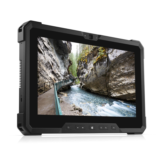
- Page 1 Latitude 12 Rugged Extreme Tablet – 7212 Owner's Manual Regulatory Model: T03H Regulatory Type: T03H002...
- Page 2 A WARNING indicates a potential for property damage, personal injury, or death. Copyright © 2017 Dell Inc. or its subsidiaries. All rights reserved. Dell, EMC, and other trademarks are trademarks of Dell Inc. or its subsidiaries. Other trademarks may be trademarks of their respective owners.
-
Page 3: Table Of Contents
Contents 1 Working on your computer..........................6 Safety instructions................................6 Before working inside your computer..........................6 Turning off your computer — Windows 10........................7 After working inside your computer..........................7 2 Removing and installing components......................8 Recommended tools................................8 Screw size list..................................8 Battery....................................9 Removing the battery..............................9 Installing the battery..............................11... - Page 4 Removing heat sink..............................33 Installing heat sink..............................33 PCIe Solid State Drive (SSD)............................34 Removing PCIe Solid State Drive (SSD)......................... 34 Installing PCIe Solid State Drive (SSD)........................35 System fan..................................35 Removing system fan..............................35 Installing system fan..............................36 System Board................................... 37 Removing system board............................
- Page 5 Wireless options................................. 68 Maintenance................................68 System Log................................. 68 Support Assist System Resolution...........................69 7 Troubleshooting............................70 Dell Enhanced Pre-Boot System Assessment (ePSA) diagnostic 3.0............... 70 Diagnostic LED................................. 70 General Troubleshooting..............................71 8 Ecosystem Accessories..........................73 Active Stylus..................................73 Getting the stylus ready for use............................. 73 System base view................................74...
-
Page 6: Working On Your Computer
Damage due to servicing that is not authorized by Dell is not covered by your warranty. Read and follow the safety instructions that came with the product. -
Page 7: Turning Off Your Computer - Windows 10
CAUTION: To avoid damage to the computer, use only the battery designed for this particular Dell computer. Do not use batteries designed for other Dell computers. Connect any external devices, such as a port replicator or media base, and replace any cards, such as an ExpressCard. -
Page 8: Removing And Installing Components
Removing and installing components This section provides detailed information on how to remove or install the components from your computer. Recommended tools The procedures in this document require the following tools: • Phillips #0 screwdriver • Phillips #1 screwdriver • Standard DSP plastic scribe Screw size list Table 1. -
Page 9: Battery
Using an incompatible battery may increase the risk of fire or explosion. Replace the battery only with a compatible battery purchased from Dell. The battery is designed to work with your Dell Tablet. Do not use a battery from any other computer with your tablet. - Page 10 The battery is released from the battery bay. Lift the edge of the battery that pops up. Removing and installing components...
-
Page 11: Installing The Battery
NOTE: There are two battery release buttons for removing Battery 1 and Battery 2 on the tablet. Ensure to remove both, before uninstalling other components of the system. Installing the battery Insert the battery into the battery slot. NOTE: Ensure the metal pin of the battery is aligned in place. Slide the battery into the slot until it clicks into place. -
Page 12: Inserting The Usim
Pull the SIM from the slot until it is released [3]. NOTE: Use a flat pointed scribe to ease removing the SIM. Press the SIM slot cap to initial state. Install the: Left battery Inserting the uSIM Remove the leftbattery To insert the uSIM: Lift the latch and remove the SIM slot cap. - Page 13 To remove the display assembly (with plastic scribe): Place the display side of system on a smooth flat surface. b Remove the 19 screws that secures the display panel to the tablet. Flip the system so that the display assembly is at top view. Removing and installing components...
- Page 14 Insert a plastic scribe near the Windows button [1]. NOTE: Pointed tip of the plastic scribe should be inserted. Pry the edges starting from Windows button clockwise [1,2]. NOTE: Gently pry the edges evenly to unlock the plastic lock that secures the display assembly with the tablet chassis. Lift the display assembly [1] by angle 15°...
- Page 15 Flip the display assembly by an angle less than 90°. NOTE: Ensure not to flip more than 90° angle, as the display assembly ports and cables are connected to the system board and may damage the display cables. Before removing display assembly: Place the bottom edge of the display panel inside the bottom edge of the rear chassis.
- Page 16 d Remove the adhesive tape that secures the Function Key cable on the system board [4]. Lift the latch by a plastic scribe and release the Touch cable connected to the system board [5]. NOTE: Disconnect only the display cable from the system board. NEVER disconnect the display cable from the display panel.
-
Page 17: Installing Display Assembly
NOTE: DO NOT remove any cable or adhesive tape from the display panel, unless you are replacing the cables separately. Installing display assembly Place the system chassis on a plane surface. Place the bottom edge of the display assembly inside the bottom edge of the rear chassis. Rest the display assembly by less than 90°... -
Page 18: Stylus
Install the: Battery Follow the procedure in After working inside your computer. Stylus Removing stylus Follow the procedure in Before working inside your computer. Locate the stylus at the top of the tablet. Pull the stylus by the thread upward. NOTE: Avoid pulling the stylus attached with the stretchable thread. -
Page 19: Wlan Card
Follow the procedure in After working inside your computer. WLAN card Removing WLAN card Follow the procedure in Before working inside your computer. Remove the: Battery Display assembly To remove the WLAN card: Place the back side of system on a flat surface. b Locate the WLAN card. -
Page 20: Installing Wlan Card
Installing WLAN card Insert the WLAN card in the slot on the system board. NOTE: Ensure that the metal pin is downwards towards the slot on the system board, and an angle LESS than 30° is maintained. Connect the WLAN cables to the connectors on the WLAN card. NOTE: Ensure that cables are aligned straight and gently press on the top to fit the cable copper head on WLAN card button pin. -
Page 21: Installing Wwan Card
Installing WWAN card Insert the WWAN card in the slot on the system board. NOTE: Ensure that the metal pin is downwards towards the slot on the system board. Connect the WWAN cables to the connectors on the WWAN card. NOTE: The IMEI number is visible on the WWAN card. -
Page 22: Installing Cmos Battery
b Locate the CMOS battery. Lift the power button cable latch by a plastic scribe and push the cable gently from the latch [1]. NOTE: Ensure to unlock the power button assembly cable to release the CMOS battery. d Remove the CMOS cable form the routing clip on the system board [2]. Push the pin connected to the system board CMOS slot by a plastic scribe [3]. -
Page 23: Power Button Assembly
Display assembly Battery Follow the procedure in After working inside your computer. Power button assembly Removing power button assembly Follow the procedure in Before working inside your computer. Remove the: Battery Display assembly To remove the power button assembly: Place the back side of system on a flat surface. b Locate the power button assembly. -
Page 24: Installing Power Button Assembly
NOTE: Power button assembly bus cable is routed between the square gap in the power button bracket. Release the adhesive tape that secures the power button assembly. g Push and release the power button assembly from the chassis by a plastic scribe [4]. h Lift and remove the power button bracket together with the power button assembly. -
Page 25: Micro Serial Port And Power Connector Port
Install the: Display assembly Battery Follow the procedure in After working inside your computer. Micro serial port and power connector port Removing micro serial port and power connector port Follow the procedure in Before working inside your computer. Remove the: Battery Display assembly To remove the micro serial port and power connector port:... - Page 26 Removing and installing components...
-
Page 27: Installing Micro Serial Port And Power Connector Port
Power connector port and micro serial port are assembled as one single component to connect on the tablet system board. NOTE: Malfunction of either component requires to remove both power connector port and micro serial port. Installing micro serial port and power connector port Insert the power connector port and micro serial port into the slot on the chassis. - Page 28 Slide the camera shutter towards right [1]. d Insert the edge of the plastic scribe between the gap of lens shutter and lift camera lens shutter [2]. Remove the screws (2) that secure the camera on the system chassis [1]. Insert the plastic scribe in the gap by an angle not more than 35°...
- Page 29 g Flip the camera circuit board with a plastic scribe [1]. h Release the latch that secures the camera cable on the system board [2]. Removing and installing components...
-
Page 30: Installing Front Camera
Installing front camera Align the front camera circuit board over the camera chassis. NOTE: Opposite side of the camera circuit board is placed to connect cable in the connector. Slide the front camera cable in the connector and release the latch. Flip the front camera circuit board, and align front camera circuit board with screw hole. -
Page 31: Microphone
Microphone Removing microphone Follow the procedure in Before working inside your computer. Remove the: Battery Display assembly To remove the microphone: Place the back side of system on a flat surface. b Locate the microphone. Lift the latch by an angle not more than 35° to unlock and gently release the power microphone cable [1]. NOTE: DO NOT pull the microphone bus cable without unreleased latch. -
Page 32: Installing Microphone
NOTE: NEVER pull the microphone by the cable. In case the circuit board is not released smoothly, push from below the microphone circuit board by a plastic scribe. Installing microphone Align the microphone system board on the tablet chassis. NOTE: Ensure that the IC on the microphone circuit board is positioned upward. -
Page 33: Heat Sink
Follow the procedure in After working inside your computer. Heat sink Removing heat sink Follow the procedure in Before working inside your computer. Remove the: Battery Display assembly To remove the heat sink: Place the back side of system on a flat surface. b Locate the heat sink. -
Page 34: Pcie Solid State Drive (Ssd)
NOTE: Ensure the SSD card in connected in the slot on the system board. Replace the screws (4) to secure the heat sink to the tablet chassis. Install the: Display assembly Battery Follow the procedure in After working inside your computer. -
Page 35: Installing Pcie Solid State Drive (Ssd)
CAUTION: Lift the SSD card by the side. DO NOT touch the circuit. Installing PCIe Solid State Drive (SSD) Slide and insert the SSD module in the connector on the system board. NOTE: Ensure that the IC on the SSD module is positioned upward in the connector on the system board. Do ensure to insert the SSD module by an angle not more than 30°... -
Page 36: Installing System Fan
Battery Display assembly Heat sink To remove the system fan: Locate the system fan. b Release the cable that connects the system fan on the system board with a plastic scribe [1]. NOTE: Push the bulge edge of the system fan connector by a plastic scribe. Remove the speaker cable from the routing channel [2]. -
Page 37: System Board
Install the: Heat sink Display assembly Battery Follow the procedure in After working inside your computer. System Board Removing system board Follow the procedure in Before working inside your computer. Remove the: Battery Display assembly Heat sink System fan WLAN WWAN Perform the following before removing the system board: Place the back side of system on a flat surface. - Page 38 d Lift the latch, and remove the power button cable [5]. Remove the CMOS battery cable from the connector on the system board [6]. Lift the latch, and remove the back camera cable [1]. g Disconnect the power button cable with a plastic scribe on the system board [2]. Removing and installing components...
- Page 39 h Remove the adhesive tape that insulates the finger print reader connector [3]. Lift the latch, and slide to remove the finger print reader cable [4]. Press the latch, and remove the USB port cable from the connector [5]. Disconnect the left I/O assembly latch, and remove the cable [1]. Disconnect the right I/O assembly latch, and remove the cable [2].
- Page 40 m Disconnect the cable [3], and remove the cable from the routing clip [4]. Remove the screws(2) that secures the antennae cable [5]. Remove the bracket that covers the antennae latch [6]. p Lift and remove the antennae cable from the connector [7]. q Release the bracket that secures the micro serial port cable with system chassis [8].
- Page 41 Push with a plastic scribe to release the DC-in cable [3], and remove the screw (1) that secures the power connector assembly cable [4]. Disconnect the battery 1 cable from the connector [5]. NOTE: Push on the connector pin head evenly to securely remove the battery cable. Disconnect the battery 2 cable from the connector [6].
- Page 42 Lift the metal bracket from the system chassis [5]. Remove the screw (6) that secures the system board to the tablet chassis [1]. Removing and installing components...
-
Page 43: Installing System Board
NOTE: Ensure to lift the system board prior to all connected cables are removed. g Insert the plastic scribe near the system fan screw slot, and slide to release and lift the system board from the tablet chassis [2]. Installing system board Align the system board with the screw holes on the tablet chassis. -
Page 44: Technology And Components
Technology and components This chapter details the technology and components available in the system. Topics: • Power adapter • USB features • Memory features Power adapter This laptop is shipped with power adapter. WARNING: When you disconnect the power adapter cable from the laptop, grasp the connector, not the cable itself, and then pull firmly but gently to avoid damaging the cable. -
Page 45: Speed
• New connectors and cable The topics below cover some of the most commonly asked questions regarding USB 3.0/USB 3.1 Gen 1. Speed Currently, there are 3 speed modes defined by the latest USB 3.0/USB 3.1 Gen 1 specification. They are Super-Speed, Hi-Speed and Full- Speed. -
Page 46: Compatibility
• External Desktop USB 3.0/USB 3.1 Gen 1 Hard Drives • Portable USB 3.0/USB 3.1 Gen 1 Hard Drives • USB 3.0/USB 3.1 Gen 1 Drive Docks & Adapters • USB 3.0/USB 3.1 Gen 1 Flash Drives & Readers • USB 3.0/USB 3.1 Gen 1 Solid-state Drives •... -
Page 47: Software
Microsoft Windows 7 on Skylake Windows 7 Professional 64bit (available through downgrade rights from Windows10 Pro License) (supported only for Intel 6th generation processors) OS Media Support • Dell.com/support to download eligible Windows OS • USB media available for upsell Downloading drivers Turn on the laptop. -
Page 48: Intel Audio Drivers
Intel audio drivers Verify if the Realtek audio drivers are already installed in the laptop. Table 4. Intel Audio drivers Before installation After installation Intel chipset drivers Verify if the Intel chipset drivers are already installed in the laptop. Table 5. Intel chipset drivers Before installation After installation Intel HD Graphics drivers... -
Page 49: Network Drivers
Network drivers Verify if the Network drivers are already installed in the laptop. Table 7. Network drivers Before installation After installation System devices drivers Verify if the System devices drivers are already installed in the laptop. Table 8. System devices drivers Before installation After installation Software... -
Page 50: Storage Drivers
Storage drivers Verify if the Storage drivers are already installed in the laptop. Table 9. Storage drivers Before installation After installation Software... -
Page 51: System Specifications
Product overview The Latitude 7212 Rugged Extreme Tablet is Dell's ruggedized tablet in the rugged portfolio. Its design is engineered for industrial and outdoor environments where customers need mobile computing power that is durable and able to perform in extreme conditions that expose the system to temperature extremes, high humidity, or pose the risk of damage from water or dust. -
Page 52: System Specifications
System specifications Feature Specification Chipset Intel Core i3/i5/i7 series DRAM bus width 128 bit (64-bits x 2 channels) Flash EPROM Quad SPI 128 Mbit PCIe bus 100 MHz External Bus PCIe Gen3 (8 GT/s) Frequency Processor specifications Feature Specification Types •... -
Page 53: Video Specifications
Feature Specification External interface Stereo headset/mic combo Speakers Two stereo speakers Internal speaker 2 W per channel amplifier Volume controls Volume buttons Video specifications Feature Specification Type Integrated on system board, hardware accelerated UMA controller iGPU GT2 graphics Data bus Integrated video External display •... -
Page 54: Display Specifications
Feature Specification • One Dual (WLAN/WWAN) RF passthrough USB ports • One USB 3.1 Gen 1 port with PowerShare • One displayPort with PowerShare over USB Type-C Memory card reader One microSD card reader SIM card slot One micro-SIM slot with security feature Modular Expansion One Pogo pin modular expansion port Display specifications... -
Page 55: Adapter Specifications
Feature Specification Power states Active, Idle and Sleep (mobile only) Adapter specifications Feature Specification Type Input voltage 100 V AC – 240 V AC Input current 0.60 A (maximum) Input frequency 50 Hz to 60 Hz Output current 2.31 — A 45 W Rated output 19.5 V DC voltage... - Page 56 Feature Specifications Temperature — -51°C to 71°C (-60°F to 160°F) storage Relative humidity 10% to 90% (non-condensing) (maximum) — operating Relative humidity 5% to 95% (non-condensing) (maximum) — storage Altitude (maximum) -16 m to 12192 m (-50 ft to 40000 ft) —...
-
Page 57: System Setup
Boot Sequence allows you to bypass the System Setup–defined boot device order and boot directly to a specific device (for example: optical drive or hard drive). During the Power-on Self Test (POST), when the Dell logo appears. you can: •... -
Page 58: System Setup Overview
Keys Navigation Spacebar Expands or collapses a drop‐down list, if applicable. Moves to the next focus area. NOTE: For the standard graphics browser only. Moves to the previous page until you view the main screen. Pressing Esc in the main screen displays a message that prompts you to save any unsaved changes and restarts the system. -
Page 59: System Configuration Screen Options
Option Description Advanced Boot Allows you the legacy option ROMs to load. By default, all the option are disabled. Options • Enable Legacy Option ROMs • Enable UEFI Network Stack • Enable Attempt Legacy Boot UEFI Boot Path Allows you to control whether or not the system will prompt to the user to enter the Admin password, when a user SecurityOptions selects a UEFI boot path from the F12 boot Menu. - Page 60 Option Description Keyboard You can choose the operating mode of the keyboard illumination feature. The keyboard brightness level can be set Illumination from 25 % to 100%. The options are: • Disabled • Level is 75% • Level is 25% •...
-
Page 61: Video Screen Options
Option Description Stealth Mode You can enable or disable the stealth mode. Control This option is enabled by default. Miscellaneous You can configure the various devices of the tablet. The options are: Devices • Enable User-Facing Camera. This option is enabled by default. •... - Page 62 Option Description • Reboot bypass Password Change Allows you to enable or disable permission to the System and Hard Drive passwords when the admin password is set. Allow Non-Admin Password Changes This option is selected by default. Non-Admin Setup Allows you to determine whether changes to the setup options are allowed when an administrator password is set. Changes If disabled the setup options are locked by the admin password.
-
Page 63: Secure Boot
Option Description Admin Setup Allows you to prevent users from entering the setup when an Administrator password is set. Lockout Enable Admin Setup Lockout This option is not selected by default. Master Password Allows you to prevent users from entering the setup when an Master password is set. Hard disk passwords need to Lockout be cleared before the setting can be changed. -
Page 64: Performance Screen Options
Performance screen options Option Description Multi Core Support This field specifies whether the process has one or all cores enabled. The performance of some applications improves with the additional cores. This option is enabled by default. Allows you to enable or disable multi-core support for the processor. - Page 65 Standard — Fully charges your battery at a standard rate. • ExpressCharge — The battery charges over a shorter period of time using Dell’s fast charging technology. • Primarily AC use Extends the battery lifespan for users who operates their system plugged in to the external power source.
-
Page 66: Post Behavior
Option Description • Custom If Custom charge is selected, you can also configure Custom Charge Start and Custom Charge Stop. NOTE: All charging mode may not be available for all the batteries. To enable this option, disable the Advanced Battery Charge Configuration option. Dock Battery You can choose the charging mode for the battery. -
Page 67: Manageability
Option Description • 10 seconds Full Screen Logo Allows you display full screen logo if your image match screen resolution. The options are: • Enable Full Screen Logo This option is disabled by default. Sign of Life Allows you to illuminate the front panel tablet buttons (Rotation Lock, Volume Down, Volume Up, Windows, P1,P2, Indication and P3) momentarily, when the power button is pressed to turn on the system. -
Page 68: Wireless Options
Option Description Trusted Execution This option specifies whether a Measured Virtual Machine Monitor (MVMM) can utilize the additional hardware capabilities provided by Intel Trusted Execution Technology. The TPM Virtualization Technology, and Virtualization technology for direct I/O must be enabled to use this feature. Trusted Execution This option is disabled by default. -
Page 69: Support Assist System Resolution
Option Description Thermal Events Allows you to view and clear the System Setup (Thermal) events. Power Events Allows you to view and clear the System Setup (Power) events. Support Assist System Resolution Option Description Auto OS Recovery Allows you to control the automatic boot flow for Support Assist System Resolution Console and for OS Recovery Threshold Tool. -
Page 70: Troubleshooting
As the rugged tablet is without keyboard, perform the following ePSA diagnostic. • To enter BIOS (system setup) without keyboard, Power on system. Press on Volume decrease button during startup (as the Dell Logo appears) until the BIOS (system setup) screen is displayed. -
Page 71: General Troubleshooting
Run the ePSA diagnostics. If the LCD has color problems, run the ePSA diagnostics. If the LCD has burned-out pixels, verify that the LCD is still within LCD standard guidelines. For Dell internal users only, click here. - Page 72 Issue Suggested Troubleshooting Steps Make sure that the network driver has been installed and is working properly. Check that the network LEDs are responding. Check System Setup to make sure that the NIC is enabled. Try reseating the cable. Try a known good cable, if one is available. If a known good system is available, check if that system is connecting to the network.
-
Page 73: Ecosystem Accessories
Ecosystem Accessories Key disassembly instructions along with important replacement instructions are called out to ensure the field technicians take into account this information before removing or replacing any components. Topics: • Active Stylus • Getting the stylus ready for use •... -
Page 74: System Base View
Insert an AAAA battery with the positive side facing the tip of the pen. Reassemble the barrel securely. System base view This section contains information on the desk dock. System right view Microphone Quad Cool vent output Security cable slot Ecosystem Accessories... -
Page 75: Dock Front View
Dock front view Tablet Back Support (Removable) Alignment pins Pogo-pin docking connector Power indicator USB 2.0 port Headset jack Keyboard Dock IP-65 Rated Full-Size Keyboard Ingress Protection (IP) ratings define levels of sealing effectiveness of electrical enclosures against intrusion. The digit 65 indicates that the rugged keyboard is enhanced with protection against dust and low-pressure water jets. To understand more on IP ratings, please refer to the Essential Knowledge page. -
Page 76: Turn The Backlight On/Off And Adjust Brightness
• Blue • Custom color • Custom color The user can set the keyboard backlight behavior and customize colors. For more information, see the Backlit Keyboard page. Press <Fn> + <C> to cycle through the available backlight colors. Turn the Backlight On/Off and Adjust Brightness Press <Fn>... -
Page 77: Dock Rear View
Fn Lock key Affected Fn keys Fn key NOTE: Fn Lock affects only these keys. Secondary functions will not require the < Fn> key to be pressed while enabled. Complete the following steps to turn the Fn Lock on/off: Press <Fn> + <Esc> to enable the Fn lock. b Secondary functions on keys in the top row will now be active with a single press of the keys. -
Page 78: I/O Module
I/O module The extended I/O Module adds two USB 3.1 ports and an Ethernet port to your Rugged Tablet. The module attaches securely to the back of the tablet when additional ports are needed. Can be easily removed when the additional extended port is not required. I/O module expands the functionality of the tablet. - Page 79 Ecosystem Accessories...