D-Link DFL-600 Manual
Hide thumbs
Also See for DFL-600:
- User manual (131 pages) ,
- Manual (113 pages) ,
- Connection manual (18 pages)
Table of Contents
Advertisement
Quick Links
Advertisement
Table of Contents

Related Manuals for D-Link DFL-600


Summary of Contents for D-Link DFL-600
- Page 1 D-Link DFL-600 Firewall/VPN Manual Rev. 1.0 Building Networks for People...
-
Page 2: Table Of Contents
Setup Wizard ............14 Home ..............20 LAN Settings............26 DHCP Settings ........... 28 NAT..............31 DMZ..............32 Advanced Settings..........38 Connecting PCs to the DFL-600 Router..... 74 Networking Basics ..........77 Contacting Technical Support ......91 Limited Warranty and Registration ..... 92... -
Page 3: Package Contents
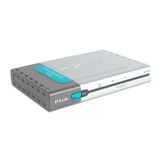
Package Contents Contents of Package: • D-Link DFL-600 Firewall/VPN Router • Manual • Quick Installation Guide • Power Adapter, 5V DC, 2.5A* • CAT-5 UTP Cable If any of the above items are missing, please contact your reseller. *Using a power supply with a different voltage rating will damage the product and void the warranty. -
Page 4: Introduction
“connected” environment. Connect the WAN port on the DFL-600 to the Cable/DSL modem using an Ethernet cable. Your entire LAN can now access the Internet using just one Internet account. - Page 5 With Firewall Protection, Hacker-attack logging, and Virtual Private Networking, the DFL-600 provides a level of security suitable for many businesses. This manual provides a quick introduction to network technology. Please take a moment to read through this manual and get acquainted with your DFL-600.
- Page 6 The DFL-600 can connect any Cable or DSL modem to the network. DHCP The DFL-600 is a DHCP-capable router. It automatically assigns unique IP Addresses to each network users that is connected to the DFL-600, for the price of one Internet account.
- Page 7 Upgradeable New Features Allows new features to be added in the future High Performance 64 bit RISC CPU Engine With the most advanced 64 bit RISC CPU Engine, DFL-600 guarantees full compatibility with future DSL/Cable technologies. IPSec Security (DES, 3DES, MD5, SHA-1)
-
Page 8: Ip Address Settings And Computer Settings
IP Address Settings and Computer Settings In order to install the DFL-600 you will need to check your computer’s settings and the values from your ISP. The information offered by your ISP: • Dynamic IP settings • Your fixed IP address for the gateway •... -
Page 9: Introduction And Overview
IP address range between 192.168.0.2 to 192.168.0.254. So computers and other devices connected to these three ports either allow the DFL-600’s DHCP server to assign them IP addresses from this range, or you can manually assign devices connected to these ports an IP address from this range. - Page 10 LAN (such as a printer or scanner). The network information (including the IP address) required by the WAN side of the DFL-600 is either obtained automatically from your ISP (or other network device on the WAN side) or is entered manually. The DFL-600 allows three methods for this information to be obtained, as follows: Dynamic −...
- Page 11 (on the same subnet) as the three LAN ports, or you will not be able to access the DFL-600 from your LAN. The many other features of the DFL-600 are described in subsequent sections.
-
Page 12: Using The Configuration Utility
Note: Please make sure that the computer you will use to connect to and configure the DFL-600 is assigned an IP address that is in the same range as the DFL-600. The IP address of the DFL-600 is 192.168.0.1. All computers on your network must be within that range, for instance, the computer IP address could be any IP address from the range 192.168.0.2 to 192.168.0.254,... - Page 13 The Setup Wizard will guide you the most basic setup tasks, such as setting an administrative password, selecting the type of WAN connection you have, entering your computer’s host name (if required by your ISP), saving the configuration and restarting the router. All other setup tasks can be accomplished using the configuration utility from your web browser.
-
Page 14: Setup Wizard
Setup Wizard The Setup Wizard will guide you through the most basic setup tasks for the DFL-600. All other configuration tasks can be accomplished through the web-based manager. The Home menu contains a Run Setup Wizard link. Click on this button to run the Setup Wizard. - Page 15 Enter a password in the Password field, and again in the Verify Password field. This will become the logon password for the DFL-600. This password is case-sensitive, so remember to use capital letters when logging on to the DFL-600’s web-based manager − if you enter a password with capital letters here.
- Page 16 (and is therefore, a dynamic IP address). DHCP is referred to as Dynamic IP address on the DFL-600. The Setup Wizard will open a page with the appropriate fields for the entry of your ISP contact information, depending upon which of the three options you choose.
- Page 17 Some ISPs require you to use an assigned host name for your Internet connection. If your ISP requires this, you can enter the assigned host name in the Host Name field. If you selected Static IP Address on the Select Internet Connection Type (WAN) wizard screen above, the following screen will open: This screen will allow you to enter the static IP address information, if your ISP has assigned a static IP address to your Internet account.
- Page 18 This screen will allow you to enter the PPPoE information, if your ISP uses the PPPoE protocol for your Internet account. Your ISP must provide this information. Click Next to continue.
- Page 19 You have completed the basic setup Wizard. The configuration now needs to be entered into the DFL-600’s flash RAM. Clicking Restart will save the configuration and restart the router.
-
Page 20: Home
Home The Home menu contains links to all of the setup menus for the DFL-600. Click on the WAN button:... - Page 21 WAN network settings. The settings listed under WAN Settings are the network settings currently in use by the DFL-600. The fields where you will enter the WAN Settings will change depending upon the choice you make in the IP Settings Mode drop-...
- Page 22 The page shown above is in Dynamic mode. Dynamic allows the DFL-600 to get its IP address information from your ISP using the Dynamic Host Configuration Protocol (DHCP). Use this setting if your ISP instructs you to use DHCP or to automatically obtain an IP address.
- Page 23 Primary DNS Server. A secondary DNS server IP address is optional. The ISP Settings page allows you to modify the way that the DFL-600 obtains its network settings from your Internet Service Provider (ISP). The entry fields on the page will change depending upon which of the following options you choose: Dynamic IP Address, Static IP Address, and PPPoE.
- Page 24 Static IP Address − If your ISP has assigned you an IP address that will never change, choose this option. When this option is chosen, the following fields appear to allow you to enter the network address information:...
- Page 25 PPPoE − If your ISP uses Point-to-Point Protocol over Ethernet (PPPoE), choose this option. When this option is chosen, the following fields appear to allow you to enter the network address information: Connect on Demand − allows the PPPoE WAN connection to be active only when a computer on your LAN makes a connection request.
-
Page 26: Lan Settings
DFL-600, enter the new values in the appropriate fields, and press Apply to make the changes current. Note: if you assign an IP address and subnet mask to the DFL-600 that is different from the IP address range assigned to the computers connected to the LAN ports, you will no longer be able to connect to the DFL-600 from any of these computers. - Page 27 DFL-600, that you configure the DFL-600’s DHCP server with the appropriate IP address range and subnet mask first, and then assign an IP address from the same range to the DFL-600. That way, a computer on the LAN side of your network can always get the proper network addressing...
-
Page 28: Dhcp Settings
DHCP (Dynamic Host Configuration Protocol) is a method of automatically assigning IP addresses, subnet masks, default gateway and DNS server IP address to computers on the LAN side of the DFL-600. The DFL-600 can be a DHCP server for your LAN, assigning IP addresses, etc. to computers on your network from a range of addresses you specify below. - Page 29 IP address is 192.168.0.1. Ending IP Address This is the last IP address in a range that the DFL-600 will assign to a computer on your network. In this case, the range of IP addresses between 192.168.0.2 to 192.168.0.100 gives 99 different IP addresses that the DFL-600 can assign to the computers on your network.
- Page 30 requests for access to your ISP’s servers. Primary DNS Server This is the IP address of a server on the Internet that provides the service of changing text URLs into IP address for sites on the Internet. The IP address of this server is provided by your ISP. Secondary DNS This is the IP address of a second DNS server, to Server...
-
Page 31: Nat
NAT is automatically applied between the IP addresses assigned to the DFL- 600’s WAN port (the IP address or addresses assigned to you by your ISP) and the IP addresses assigned to the DFL-600’s LAN ports (the 192.168.0.x subnet). NAT is not used between the WAN port and the DMZ port. -
Page 32: Dmz
NAT and the firewall features of your DFL-600 may conflict with certain interactive applications such as video conferencing or playing Internet video games. For these applications, a bypass can be set up using the DMZ port and a corresponding DMZ IP address. The DMZ IP address is “visible” to the Internet (or WAN) and does not benefit from the full protection of the NAT function. - Page 33 The DMZ Settings screen allows you to Enable and Disable the DMZ port on the DFL-600 and to specify the IP address and Subnet Mask that the DMZ port will use. The default DMZ IP address is 192.168.1.1 with a subnet mask of 255.255.255.0.
- Page 34 The DMZ port maps one global IP address − an IP address that is valid on the Internet, usually assigned by your ISP − to one local IP address from the IP address range assigned to the DFL-600’s DMZ port. DMZ Hosts, sometimes referred to as Virtual Servers, are computers on your LAN that are connected to the DMZ port and are configured to act as servers to connections to the WAN or Internet.
- Page 35 protocol that the application on the DMZ computer will use. ~user defined~ allows you to manually enter the TCP or UDP port number that the application will use to connect to the Internet. The remaining protocols in the list have the appropriate TCP or UDP port number already entered.
- Page 36 Time Settings The DFL-600 can be set to obtain and distribute the correct time to computers on your LAN using the Simple Network Time Protocol (SNTP). Click on the Time button to open the following page: Displays the current system date and time.
- Page 37 Set Type This drop-down menu allows you to select either the IP address of an SNTP server, or the Domain Name (URL) of an SNTP server that the DFL- 600 will contact to obtain the correct date and time. Enter the IP address of an SNTP server here. IP address Domain Name Enter the Domain Name (URL) of an SNTP...
-
Page 38: Advanced Settings
Virtual Servers Virtual Servers allow remote users to access services on your LAN such as FTP for file transfers or SMTP and POP3 for e-mail. The DFL-600 will accept remote requests for these services at a Global IP Address you specify,... - Page 39 Private IP This is the IP address of the server on your LAN that will provide the service to remote users. You can select the transport protocol (TCP or Transport Type UDP) that the application on the virtual server will use for its connections. The choice of this protocol is dependent on the application that is providing the service.
- Page 40 These applications often conflict with NAT, and therefore require special handling. The Special Applications page allows you to configure your DFL-600 to allow computers on your LAN to access servers on the WAN that require multiple TCP or UDP connections.
- Page 41 TCP/UDP packet. When a TCP or UDP packet is received by the DFL-600, the IP address in this packet will be translated between the WAN and LAN side of the DFL-600, if this option is enabled. Replacement Format...
- Page 42 Static Routing Your DFL-600 can automatically discover routes to destinations on both your LAN and the WAN (Internet). In addition, you can add entries to the DFL- 600’s routing table that will be saved to flash RAM. These routes will not...
- Page 43 Policy (Firewall Settings) The DFL-600 allows you to specify a range of IP addresses, MAC addresses, TCP/UDP port numbers, and Domain names for connections between computers on the WAN and computers on your LAN that will be controlled.
- Page 44 Port Filter Status When Enable is selected from this drop-down menu, the Port Filter will be applied to packets both coming from and going to the WAN. When Disable is selected, the Port Filter is inactive. IP Range Filter Status When Enable is selected from this drop-down menu, the IP Filter will be applied to packets going to the WAN.
- Page 45 Firewall Settings − Port Filter Policy The DFL-600 allows you to specify a range of TCP or UDP ports for connections between computers on the WAN and computers on your LAN that will be controlled. These TCP or UDP ports are entered on the Port Filter page.
- Page 46 the protocol is identified by name. For example, the Simple Mail Transfer Protocol (SMTP in the drop-down menu) is used to send and receive e-mail. It uses the TCP transport protocol and port number 25. This information will be entered for you, if you select SMTP from the Protocol drop-down menu.
- Page 47 IP Range Filter The IP Range Filter page allows you to deny access to the WAN (Internet) from specific computers on your LAN, by specifying the computer’s IP address on the WAN (Internet). Source IP Address This allows you to specify the first in a range of From IP addresses that the IP filter policy will be applied to.
- Page 48 IPSec Pass-through Click Enable to allow IPSec packets to pass through the router to the destination computer on your LAN. When IPSec Pass-through is enabled, the DFL-600 will allow IPSec packets to reach their destination computer on your LAN. IPSec Status...
- Page 49 IPSEC Tunnel Mode The IPSEC Tunnel Mode page allows you to setup a secure tunnel between your DFL-600 and a remote gateway. Add/New Tunnel The following fields will identify the VPN tunnel on the DFL-600. Tunnel ID An alphanumeric string that identifies the...
- Page 50 Aggressive mode, there is no encryption in the Phase 1 negotiation. DH Group The DH algorithm allows the DFL-600 to generate secret keys for encryption for the Phase 1 negotiation. Group 1 generates a 768- bit key and Group 2 generates a 1024-bit key.
- Page 51 triggered to build a new tunnel. IKE Hash This drop-down menu allows you to select the algorithm that will be used to ensure that the messages exchanged between the two IPSec VPN tunnel endpoints has been received exactly as it was sent. In other words, a Hash algorithm is used to generate a binary number by a mathematical operation using the entire message.
- Page 52 uses 768-bit encryption, and Group 2 uses 1024-bit encryption. You must use exactly the same PFS encryption mode on both ends of the VPN tunnel. IPSec Operation This drop-down menu allows you to select the level of encryption that will be applied to packets that are sent between the two endpoints of a VPN tunnel.
- Page 53 encryption algorithm that will be used when ESP is selected in the IPSec Operation drop- down menu above. You can choose between Null − no authorization, MD5 − using MD5 message digest authentication, and SHA − using the SHA authentication method. You must select the exact same ESP authentication method on both ends of a VPN tunnel.
- Page 54 192.168.2.1 to 192.168.2.254 will be allowed to access the VPN. Note that the IP addresses192.168.2.0 and 192.168.2.255 are reserved for use on the remote network. Subnet Mask Enter the subnet mask corresponding to the IP address range entered above. Tunnel Table The Tunnel Table displays the current tunnel setup.
- Page 55 IPSec Status Click on the IPSec Status link to display the current IPSec status table, as shown below. VPN-PPTP Settings The Point-to-Point Tunneling Protocol (PPTP) is another method of establishing a secure tunnel between the DFL-600 and a remote gateway.
- Page 56 Click Enable to allow PPTP packets to pass through the router to the destination computer on your LAN. When IPSec Pass-through is enabled, the DFL-600 will allow PPTP packets to reach their destination computer on your LAN. PPTP can be Enabled or Disabled by clicking...
- Page 57 The PPTP Account settings page allows you to enter a username and password for a PPTP account. A combined maximum of 64 PPTP and L2TP user accounts can be configured on the DFL-600. Username Enter the appropriate username for your PPTP account here.
- Page 58 The Layer 2 Tunneling Protocol (L2TP) is another method of establishing a secure tunnel between your DFL-600 and a remote gateway. The L2TP Status page allows you to enable or disable L2TP on the DFL-600. L2TP Pass Through Click Enable to allow L2TP packets to pass through the router to the destination computer on your LAN.
- Page 59 Enter your L2TP account password here. Confirm Password Re-enter your L2TP account password here to verify it has been entered correctly. L2TP Status Click on the L2TP Status link to display the current status of an L2TP tunnel on the DFL-600, as shown below.
- Page 60 Tools − Administration The Admin Settings page allows you to add or edit the Username and Password list to control access to the configuration of the DFL-600. A default user account is configured with the username admin, and a password of admin. You can change the password at any time.
- Page 61 If you choose the Restore Factory Default Settings option, all of the configuration settings you have entered will be erased and the DFL-600 will be restored to the same configuration it had when it left the factory.
- Page 62 The Firmware Upgrade page allows you to upgrade the DFL-600’s firmware from a new firmware file stored on your local hard drive. In addition, you can choose to load the DFL-600’s current VPN or Firewall settings to a hard drive on a local computer. Clicking on the OK button will initiate a download of either the VPN settings (as a text file named DFL600_vpn.txt) or the Firewall settings (as a text file named...
- Page 63 Update File Enter the full DOS path and filename to the new firmware file on your local hard drive. For example, if the file is in the root directory of your C drive, enter C:\newfile.had and click the OK button to begin the file transfer. If you are unsure about the location of the new Browse firmware file on your local hard drive, click the...
- Page 64 Status − Device Info The Device Information page displays the current network settings and allows you to view the IP address assigned to the DFL-600 by your ISP using DHCP (Dynamic Host Configuration Protocol − the Dynamic IP Address setting on the WAN Settings page under the Home page).
- Page 65 LAN Status MAC Address This is the MAC address of the DFL-600 on the LAN. IP Address This is the DFL-600’s current IP address on the LAN. Subnet Mask This is the subnet mask corresponding to the IP address above − that is currently in use by the DFL-600 on the LAN.
- Page 66 DFL-600 Status − Log Info Your DFL-600 can keep logs of the various functions it supports. The Log Status page allows you to enable or disable each of these logs using a series of drop-down menus.
- Page 67 Certain sessions between computers on your LAN and the WAN have the potential to cause a disruption in the function of your computers and are blocked by the DFL-600’s firewall. Some of these session types are pre- defined by the factory, and are commonly used intrusion methods. Events...
- Page 68 Certain sessions between computers on your LAN and the WAN have the potential to cause a disruption in the function of your computers and are blocked by the DFL-600’s firewall. Some of these session types are defined by you under on the Port Filter Policy page, under Policy Settings from the Advanced Settings tab.
- Page 69 Session Log Session events (when a computer on your LAN accesses an application of service on the WAN), are logged by the DFL-600 and are displayed on the Session Log, as shown below: The IP address and TCP/UDP port number of the...
- Page 70 Once the intruder’s information is entered, the DFL-600’s firewall will block packets from this location from crossing the DFL-600 (from the WAN to the LAN, from two computers on the LAN, or from the LAN to the WAN). Once an intruder’s IP address is listed in the Intruder Blacklist, it will remain until it times out.
- Page 71 IPSec Log The DFL-600 maintains a table containing statistics concerning the IPSec protocol connection between the WAN and the LAN. These statistics can be viewed on the IPSEC Statistics table, as shown below: Index This displays the sequence of the IPSec log.
- Page 72 Sys Log The DFL-600 can save or transmit Syslog messages to aid in network administration. You must have a Syslog application on one of the computers on your LAN to take advantage of this feature. Clicking on the Sys Log link will open the Sys Log configuration page, as shown below.
- Page 73 Status − Traffic Log Your DFL-600 keeps a log of the total number of bytes received and transmitted on to and from the LAN and WAN. This information can be displayed by clicking on the Traffic button to display the Traffic Statistics...
-
Page 74: Connecting Pcs To The Dfl-600 Router
Connecting PCs to the DFL-600 Router If you do not wish to set the static IP address on your PC, you will need to configure your PC to request an IP address from the gateway. Click the Start button, select Settings then select Control Panel. - Page 75 Click the Properties button, then choose the IP Address tab. Select Obtain an IP address automatically. After clicking OK, windows might ask you to restart the PC. Click Yes. CONFIRM YOUR PC’S IP CONFIGURATION There are two tools which are great for finding out a computer’s IP configuration: MAC address and default gateway.
- Page 76 • IPCONFIG (for Windows 2000/NT/XP) In the DOS command prompt type IPCONFIG and press Enter. Your PC IP information will be displayed as shown below.
-
Page 77: Networking Basics
Networking Basics Using the Network Setup Wizard in Windows XP In this section you will learn how to establish a network at home or work, using Microsoft Windows XP. Note: Please refer to websites such as http://www.homenethelp.com http://www.microsoft.com/windows2000 for information about networking computers using Windows 2000, ME or 98. - Page 78 Please follow all the instructions in this window: Click Next In the following window, select the best description of your computer. If your computer connects to the Internet through a gateway/router, select the second option as shown.
- Page 79 Click Next Enter a Computer description and a Computer name (optional.) Click Next...
- Page 80 Enter a Workgroup name. All computers on your network should have the same Workgroup name. Click Next Please wait while the wizard applies the changes.
- Page 81 When the changes are complete, Click Next. Please wait while the wizard configures the computer. This may take a few minutes.
- Page 82 In the window below, select the best option. In this example, “Create a Network Setup Disk” has been selected. You will run this disk on each of the computers on your network. Click Next. Insert a disk into the Floppy Disk Drive, in this case drive “A:”...
- Page 83 Format the disk if you wish, and Click Next. Please wait while the wizard copies the files. Please read the information under Here’s how in the screen below. After you complete the Network Setup Wizard you will use the Network Setup Disk to run the Network Setup Wizard once on each of the computers on your network.
- Page 84 The new settings will take effect when you restart the computer. Click Yes to restart the computer. You have completed configuring this computer. Next, you will need to run the Network Setup Disk on all the other computers on your network. After running the Network Setup Disk on all your computers, your new wireless network will be ready to use.
- Page 85 Naming your Computer Naming your computer is optional. If you would like to name your computer please follow these directions: In Windows XP: Click START (in the lower left corner of the screen) Right-click on My Computer Select Properties • Select the Computer Name Tab in the System Properties window.
- Page 86 • In this window, enter the Computer name. • Select Workgroup and enter the name of the Workgroup. • All computers on your network must have the same Workgroup name. • Click OK...
- Page 87 Assigning a Static IP Address Note: Residential Gateways/Broadband Routers will automatically assign IP Addresses to the computers on the network, using DHCP (Dynamic Host Configuration Protocol) technology. If you are using a DHCP-capable Gateway/Router you will not need to assign Static IP Addresses. If you are not using a DHCP capable Gateway/Router, or you need to assign a Static IP Address, please follow these instructions: Go to START...
- Page 88 Right-click on Local Area Connections. Double-click Properties Highlight Internet Protocol (TCP/IP) Click Properties...
- Page 89 Select Use the following IP address in the Internet Protocol (TCP/IP) Properties window. Input your IP address and subnet mask. (The IP Addresses on your network must be within the same range. For example, if one computer has an IP Address of 192.168.0.2, the other computers should have IP Addresses that are sequential, like 192.168.0.3 and 192.168.0.4.
- Page 90 You have completed the assignment of a Static IP Address. (You do not need to assign a Static IP Address if you have a DHCP-capable Gateway/Router.)
-
Page 91: Contacting Technical Support
Contacting Technical Support You can find the most recent software and user documentation on the D-Link website. D-Link provides free technical support for customers within the United States for the duration of the warranty period on this product. U.S. customers can contact D-Link technical support through our web site, or by phone. -
Page 92: Limited Warranty And Registration
Such repair or replacement will be rendered by D-Link at an Authorized D-Link Service Office. The replacement Hardware need not be new or of an identical make, model or part; D-Link may in its discretion replace the defective Hardware (or any part thereof) with any reconditioned product that D-Link reasonably determines is substantially equivalent (or superior) in all material respects to the defective Hardware. - Page 93 D-Link Systems Inc., 53 Discovery Drive, Irvine CA 92618. D-Link may reject or return any product that is not packaged and shipped in strict compliance with the foregoing requirements, or for which an RMA number is not visible from the outside of the package. The product owner agrees to pay D-Link’s reasonable handling and return shipping charges for any product that is not packaged and...
- Page 94 Increase the separation between the equipment and receiver. • Connect the equipment into an outlet on a circuit different from that to which the receiver is connected. • Consult the dealer or an experienced radio/TV technician for help. Register Your D-Link Product Online at http://www.dlink.com/sales/reg...