Siemens SINAMICS DCM Operating Instructions Manual
Control module for variable-speed dc drives
Hide thumbs
Also See for SINAMICS DCM:
- List manual (1205 pages) ,
- Operating instructions manual (715 pages) ,
- Manual (705 pages)
Table of Contents
Advertisement
Quick Links
Download this manual
See also:
User Manual
Advertisement
Table of Contents

Related Manuals for Siemens SINAMICS DCM


Summary of Contents for Siemens SINAMICS DCM
- Page 1 SINAMICS DCM Control Module for variable-speed DC drives Operating instructions 6/2010 Edition SINAMICS drives...
- Page 3 Preface Notes Ordering information SINAMICS Description SINAMICS DCM Control Module Technical data Transport, unpacking, installation Operating Instructions Connecting Additional system components Commissioning Operation Descriptions of functions Maintenance Applications Appendix A Appendix B Software version 1.2 06.2010 C98130-A7067-A1-02-7619...
-
Page 4: Technical Data
Note the following: WARNING Siemens products may only be used for the applications described in the catalog and in the relevant technical documentation. If products and components from other manufacturers are used, these must be recommended or approved by Siemens. Proper transport, storage, installation, assembly, commissioning, operation and maintenance are required to ensure that the products operate safely and without any problems. -
Page 5: Preface
● SINAMICS DC MASTER Unit software version As these Operating Instructions went to print, SINAMICS DCM Control Modules were being supplied from the factory with software release specified on Page 3. However, these Operating Instructions can, in principle, also apply to other software versions. -
Page 6: C98130-A7067-A1
Our technical support service can provide you with technical assistance for products, systems, and solutions. www.siemens.de/automation/support-request (German) www.siemens.com/automation/support-request (English) Central hotlines for SINAMICS DCM technical support European and African time zone Phone: +49 (0)911 895 7222 8:00 to 17:00 CET Fax: +49 (0)911 895 7223 mailto:support.automation@siemens.com... - Page 7 Spare parts You can find information on spare parts ● in Catalog D23 ● on the SINAMICS DCM documentation DVD (to reorder please quote order number 6RX1800-0AD64) ● in the internet http://support.automation.siemens.com/WW/view/de/38157755/133100 ● in the electronics spare parts catalog, Spares On Web, by entering the serial and order number of your SINAMICS DCM.
- Page 8 Preface SINAMICS DCM Control Module Operating Instructions, 06.2010, C98130-A7067-A1-02-7619...
-
Page 9: Table Of Contents
Data on the line-side harmonics from converter units in a fully-controlled AC bridge circuit B2C ..............................66 Cable routing in the unit .......................67 Block diagram with connection suggestion..................70 Connecting the external power unit .....................73 Division options ..........................80 SINAMICS DCM Control Module Operating Instructions, 06.2010, C98130-A7067-A1-02-7619... - Page 10 Meanings of the LEDs on the Communication Board Ethernet CBE20........146 7.1.4 Installation ..........................148 7.1.5 Technical specifications ......................148 Sensor Module Cabinet-Mounted SMC30 ................149 7.2.1 Description ..........................149 7.2.2 Safety instructions........................149 7.2.3 Interface description........................151 SINAMICS DCM Control Module Operating Instructions, 06.2010, C98130-A7067-A1-02-7619...
- Page 11 7.4.3.13 Cause and rectification of faults....................187 7.4.4 Dimension drawing ........................188 7.4.5 Installation ..........................189 7.4.6 Electrical connection ........................190 7.4.7 Technical data..........................192 Commissioning ............................193 Switching on..........................195 Commissioning using the BOP20 Operator Panel..............196 8.2.1 Preconditions ..........................196 8.2.2 Commissioning steps.........................196 SINAMICS DCM Control Module Operating Instructions, 06.2010, C98130-A7067-A1-02-7619...
- Page 12 Internal encoding of the binector/connector output parameters ..........275 9.1.5.5 Example: Interconnecting digital signals................... 275 9.1.5.6 Information on BICO technology....................276 Parameterizing using the BOP20 (Basic Operator Panel 20)........... 277 9.2.1 General information about the BOP20..................277 SINAMICS DCM Control Module Operating Instructions, 06.2010, C98130-A7067-A1-02-7619...
- Page 13 10.2.8.4 Commissioning of the PROFIBUS slave-to-slave communication ..........324 10.2.8.5 Diagnosing the PROFIBUS slave-to-slave communication in STARTER .........336 10.3 PROFINET IO ..........................337 10.3.1 Activating online mode: STARTER via PROFINET IO ..............337 10.3.2 General information about PROFINET IO .................343 SINAMICS DCM Control Module Operating Instructions, 06.2010, C98130-A7067-A1-02-7619...
- Page 14 Thermal overload protection for the DC motor (I2t monitoring of the motor)......404 10.18 Measuring the motor temperature..................... 407 10.19 Speed-dependent current limitation ..................409 10.20 Thyristor blocking voltage calculation ..................412 10.21 Automatic restart ........................413 SINAMICS DCM Control Module Operating Instructions, 06.2010, C98130-A7067-A1-02-7619...
- Page 15 10.24.1 Direction of rotation reversal using field reversal...............434 10.24.2 Braking using field reversal......................436 10.25 Serial interface with peer-to-peer protocol.................439 10.26 Expanding the SINAMICS DCM to include a second CUD ............444 10.27 Runtime (operating hours counter) ....................446 10.28 Diagnostics..........................447 10.28.1 Diagnostic memory ........................447 10.28.2 Trend recorder function......................447...
- Page 16 Table of contents Servicing............................ 494 Appendix B ............................495 Runtimes of the DCC blocks for SINAMICS DCM..............495 BOP20 status display during power-up..................500 Feedback........................... 501 Index..............................503 SINAMICS DCM Control Module Operating Instructions, 06.2010, C98130-A7067-A1-02-7619...
-
Page 17: Notes
Any obligations on the part of Siemens arise from the respective contract of sale, which also contains the solely valid warranty conditions in full. Any statements contained in these Operating Instructions neither expand nor restrict the scope of these contractual warranty conditions. -
Page 18: Maintenance
3. The unit must be operated with all covers supplied. The fixing screws for the front cover of the SINAMICS DCM must be tight. When required, additional covers should be provided in the control cabinet. -
Page 19: Esd-Sensitive Components
The necessary ESD protection measures are elucidated once again in the following illustration: Seated Standing Seated/standing a conductive floor b ESD Table c ESD footwear " ESD smock " e ESD wrist strap cubicle ground connection SINAMICS DCM Control Module Operating Instructions, 06.2010, C98130-A7067-A1-02-7619... - Page 20 Notes 1.2 ESD-sensitive components SINAMICS DCM Control Module Operating Instructions, 06.2010, C98130-A7067-A1-02-7619...
-
Page 21: Ordering Information
Ordering information Unit order numbers Without option: 6RA8000 - 0MV62 - 0AA0 With options: 6RA8000 - 0MV62 - 0AA0 - Z SINAMICS DCM Control Module Operating Instructions, 06.2010, C98130-A7067-A1-02-7619... -
Page 22: Rating Plates, Packaging Label
For options: "Z" after order number ③ Order codes for options (according to ordering information for options) (order-specific) ④ Serial number bar code (order-specific) ⑤ Product version Rating plate on front cover Rating plate in unit SINAMICS DCM Control Module Operating Instructions, 06.2010, C98130-A7067-A1-02-7619... - Page 23 Ordering information 2.2 Rating plates, packaging label ① For options: "Z" after order number, followed by order codes (according to ordering information for options) Figure 2-1 Packaging label SINAMICS DCM Control Module Operating Instructions, 06.2010, C98130-A7067-A1-02-7619...
-
Page 24: Ordering Information For Options And Accessories
Ordering information for accessories Table 2- 3 Order numbers for documentation Item Order number Set of manuals, German 6RX1800-0JD00 SINAMICS DCM Control Module Operating Instructions, German 6RX1800-0BD00 SINAMICS DCM List Manual, German 6RX1800-0ED00 Free Function Blocks Manual, German 6RX1800-0FD00 SINAMICS DCM Control Module... - Page 25 Ordering information 2.3 Ordering information for options and accessories Item Order number Set of manuals, English 6RX1800-0JD76 SINAMICS DCM Control Module Operating Instructions, English 6RX1800-0BD76 SINAMICS DCM List Manual, English 6RX1800-0ED76 Free Function Blocks Manual, English 6RX1800-0FD76 Set of manuals, French (includes the Free Function Blocks Manual in English)
- Page 26 50 m Ordering information for cable sets The SINAMICS DCM Control Module is supplied with front and rear plates mounted one on top of the other. The correct ribbon cables for this mounting type are already in place. The cable sets listed below for connecting components (printed circuit boards or their parts) in the case of other mounting types (see Chapter 6) are available on request.
- Page 27 XS9_2, XS10_2, XS11_2, XS12_2 or XS1_1, XS2_1, XS3_1, XS4_1, XS5_1, XS6_1, XS7_1, XS8_1, XS9_1, XS10_1, XS11_1, XS12_1 depending on the voltage (50 V, 125 V, 250 V, 575 V, or 1,000 V) to fuses SINAMICS DCM Control Module Operating Instructions, 06.2010, C98130-A7067-A1-02-7619...
- Page 28 XF1 on PCB -A7109- shielded (L = 0.76 m) to XF1 on PCB -A7116- 1 x RJ45 patch cable, shielded X45 on PCB -A7109- (L = 1 m) to X45 on PCB -A7117- SINAMICS DCM Control Module Operating Instructions, 06.2010, C98130-A7067-A1-02-7619...
-
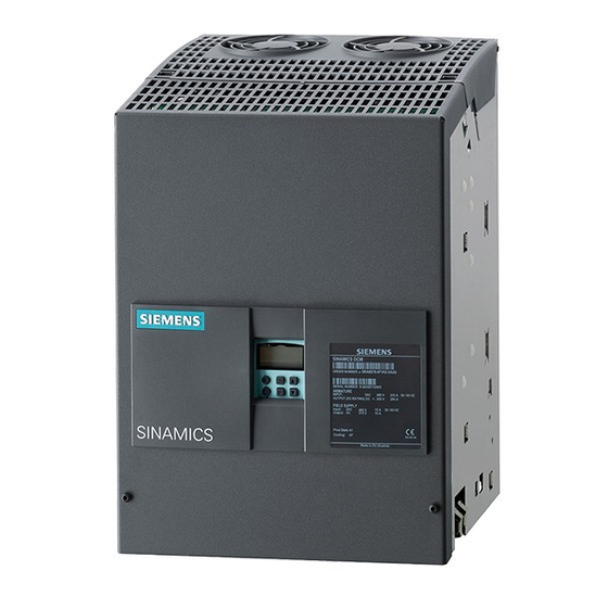
Page 29: Description
SINAMICS DCM Control Module. This is a highly cost- effective solution for those interested in a modern DC drive with the entire range of functions associated with the fully digital units in the SINAMICS DCM range. - Page 30 ● Additional (second) CUD (Standard or Advanced) (option) This additional CUD can be fitted to the right of the first CUD and is used for system- specific extension of the SINAMICS DCM functions. Additional components ● Advanced Operator Panel AOP30 The optional Advanced Operator Panel AOP30 is mounted outside of the unit - in the control cabinet door, for example - rather than inside it.
- Page 31 The CUD in the right-hand slot is primarily available (in addition to the operating system) for one DCC function diagram only. SINAMICS DCM Control Module Operating Instructions, 06.2010, C98130-A7067-A1-02-7619...
- Page 32 Description SINAMICS DCM Control Module Operating Instructions, 06.2010, C98130-A7067-A1-02-7619...
-
Page 33: Technical Data
Technical data Note You can find the technical data for the connectors and terminals in the section titled "Connecting". SINAMICS DCM Control Module Operating Instructions, 06.2010, C98130-A7067-A1-02-7619... -
Page 34: Environmental Conditions
0 ... +55 In order to ensure sufficient cooling for the electronics components, the supply air temperature needs to be reduced by 3.5 K/500 m for altitudes more than 1,000 m above sea level. SINAMICS DCM Control Module Operating Instructions, 06.2010, C98130-A7067-A1-02-7619... -
Page 35: Unit Data
• Temperature coefficient of tachometer generator with temperature compensation: 0.15‰ every 10 °C (with analog tachometer generator only) • Constant setpoint (14-bit resolution) The option of operating with an extended frequency range can be provided on request. SINAMICS DCM Control Module Operating Instructions, 06.2010, C98130-A7067-A1-02-7619... - Page 36 Technical data 4.2 Unit data SINAMICS DCM Control Module Operating Instructions, 06.2010, C98130-A7067-A1-02-7619...
-
Page 37: Transport, Unpacking, Installation
The packaging materials consist of the carton and corrugated cardboard, and can be disposed of in accordance with local regulations for cardboard packaging. If you discover any damage that has occurred in transit, please inform your shipping agent immediately. SINAMICS DCM Control Module Operating Instructions, 06.2010, C98130-A7067-A1-02-7619... -
Page 38: Installation
The unit should only be lifted with suitable equipment (work gloves should be used) and by appropriately qualified personnel. The user assumes responsibility for installing the SINAMICS DCM Control Module, power unit, motor, transformer, and other units in accordance with safety regulations (e.g. EN, DIN, VDE) and all other relevant national or local regulations concerning conductor dimensioning, protection, grounding, disconnectors, overcurrent protection, and so on. -
Page 39: Dimension Drawings
Transport, unpacking, installation 5.2 Installation 5.2.1 Dimension drawings All dimensions given in mm Tolerance for external dimensions is +2 mm Figure 5-1 Unit components after assembly (on delivery) SINAMICS DCM Control Module Operating Instructions, 06.2010, C98130-A7067-A1-02-7619... - Page 40 Transport, unpacking, installation 5.2 Installation Figure 5-2 Unit components arranged alongside each other SINAMICS DCM Control Module Operating Instructions, 06.2010, C98130-A7067-A1-02-7619...
-
Page 41: Dividing The Unit
② ③ Pull the front cover towards you and then upwards to remove it Unplug the cable connections between the two plates. ④ Loosen the screws Figure 5-3 Dividing the unit (1) SINAMICS DCM Control Module Operating Instructions, 06.2010, C98130-A7067-A1-02-7619... - Page 42 Transport, unpacking, installation 5.2 Installation ① ② Pull the plate towards you and remove it Figure 5-4 Dividing the unit (2) SINAMICS DCM Control Module Operating Instructions, 06.2010, C98130-A7067-A1-02-7619...
-
Page 43: Removal/Installation And Division Of Modules
To remove other modules, remove the shield by pulling it towards you. You will need to unscrew the field terminal ② and then loosen the screws before doing this. Figure 5-5 Removing modules (1) SINAMICS DCM Control Module Operating Instructions, 06.2010, C98130-A7067-A1-02-7619... - Page 44 To remove fuse monitoring equipment A7118, pull the cables out from the module and loosen the screws ② To remove voltage measurement equipment A7117, pull the cables out from the module and loosen the screws Figure 5-6 Removing modules (2) SINAMICS DCM Control Module Operating Instructions, 06.2010, C98130-A7067-A1-02-7619...
-
Page 45: Firing Pulse Transformers C98043-A7043
Use the edge of a table to separate the two terminal parts ② Use the edge of a table to separate the small control boards Figure 5-7 Dividing the A7043 firing pulse transformers SINAMICS DCM Control Module Operating Instructions, 06.2010, C98130-A7067-A1-02-7619... - Page 46 Transport, unpacking, installation 5.2 Installation Installing terminal strips ① Leave the two crossbraces for supporting the side sections of the modules in the unit. Figure 5-8 Installing the A7043 firing pulse transformers SINAMICS DCM Control Module Operating Instructions, 06.2010, C98130-A7067-A1-02-7619...
- Page 47 The 2 snap-on parts for the DIN rail, which satisfies DIN EN 50022-35x7.5, are mounted on the small control boards ② with M3x8 screws Figure 5-10 External mounting of the small firing pulse transformer boards SINAMICS DCM Control Module Operating Instructions, 06.2010, C98130-A7067-A1-02-7619...
-
Page 48: Fuse Monitoring Equipment C98043-A7118 And Voltage Measurement Equipment C98043-A7117
External mounting of fuse monitoring equipment C98043-A7118 Mount the module on the spacing bolts. ① Ferrous fixing elements (x2) ② Insulating fixing elements (x5) Figure 5-11 External mounting of the fuse monitoring equipment SINAMICS DCM Control Module Operating Instructions, 06.2010, C98130-A7067-A1-02-7619... - Page 49 External mounting of voltage measurement equipment C98043-A7117 Mount the module on the spacing bolts. ① Ferrous fixing elements (x2) ② Insulating fixing elements (x4) Figure 5-12 External mounting of the voltage measurement equipment SINAMICS DCM Control Module Operating Instructions, 06.2010, C98130-A7067-A1-02-7619...
-
Page 50: Installing Options And Accessories
Installing a second CUD CAUTION Please observe the information provided on "Electrostatic sensitive devices (ESD)" in Chapter 1. ① Unlock and tilt up the BOP support • Figure 5-13 Installing a second CUD (1) SINAMICS DCM Control Module Operating Instructions, 06.2010, C98130-A7067-A1-02-7619... - Page 51 Secure the CUD using 4 screws (screw and washer assembly, M3×6), tightening torque 1 Nm • Figure 5-14 Installing a second CUD (2) Lock the BOP support again. • CAUTION: Do not clamp the BOP cable Figure 5-15 Installing a second CUD (3) SINAMICS DCM Control Module Operating Instructions, 06.2010, C98130-A7067-A1-02-7619...
- Page 52 Transport, unpacking, installation 5.2 Installation SINAMICS DCM Control Module Operating Instructions, 06.2010, C98130-A7067-A1-02-7619...
-
Page 53: Connecting
Connecting WARNING The manufacturer can only provide an assurance that the SINAMICS DCM Control Module will function properly and accept any liability for damage if the unit has been installed and commissioned by experts and the contents of these Operating Instructions have been correctly followed. - Page 54 Connecting WARNING The user is responsible for ensuring that the motor, the SINAMICS DCM Control Module, and other units are installed and connected in accordance with recognized engineering practice in the country of installation and in compliance with applicable regional regulations.
-
Page 55: Instructions For Emc-Compliant Drive Installation
Should you require further information or encounter specific problems which have not been dealt with in enough detail for your field of application, please contact your local Siemens office. The contents of these installation instructions neither form part of nor modify any prior or existing contract, agreement, or legal relationship. - Page 56 Drive systems for rated voltages ≥ 1,000 V or for rated currents ≥ 400 A for use in complex systems in the second environment The figure below shows how the four categories are assigned to the first and second environments: SINAMICS DCM Control Module Operating Instructions, 06.2010, C98130-A7067-A1-02-7619...
- Page 57 If all the control components in the system (such as PLCs) demonstrate a level of interference immunity that is suitable for industrial applications, then it is not necessary for every drive to adhere to limit value "A1". SINAMICS DCM Control Module Operating Instructions, 06.2010, C98130-A7067-A1-02-7619...
-
Page 58: Emc-Compliant Drive Installation (Installation Instructions)
In order to ensure electromagnetic compatibility (EMC) in your control cabinets in rugged electrical environments and adhere to the standards required by the relevant legislating body, the EMC rules listed below should be followed during the construction and design stages. SINAMICS DCM Control Module Operating Instructions, 06.2010, C98130-A7067-A1-02-7619... - Page 59 (ground) at several points, and connected at several points outside the control cabinet. Foil shields should be avoided as they are are at least 5 times less effective than braided shields. SINAMICS DCM Control Module Operating Instructions, 06.2010, C98130-A7067-A1-02-7619...
- Page 60 Generally speaking, "ground" refers to all metallic conductive parts that can be connected to a protective conductor, such as the cabinet enclosure, motor enclosure, or foundation ground. Cabinet configuration and shielding Figure 6-3 Shielding at control cabinet inlet SINAMICS DCM Control Module Operating Instructions, 06.2010, C98130-A7067-A1-02-7619...
- Page 61 Connecting 6.1 Instructions for EMC-compliant drive installation Figure 6-4 Shielding in control cabinet Connecting shields on the SINAMICS DC MASTER Figure 6-5 Connecting shields SINAMICS DCM Control Module Operating Instructions, 06.2010, C98130-A7067-A1-02-7619...
- Page 62 Notice! Risk of pinching cable if screws tightened too much ③ Ferrous tube or cable tie on bare ferrous comb-type/toothed bar ④ Clamp with ferrous backing plate on cable support rail Figure 6-7 Shield connection SINAMICS DCM Control Module Operating Instructions, 06.2010, C98130-A7067-A1-02-7619...
-
Page 63: Arranging Components For Converter Units
Line supply – radio interference suppression filter – commutating reactor – power unit. An incorrect arrangement can destroy a thyristor (short-circuit) and rupture a fuse. Catalog LV60 is used for selecting line reactors. SINAMICS DCM Control Module Operating Instructions, 06.2010, C98130-A7067-A1-02-7619... -
Page 64: Information On Line-Side Harmonics Produced By Converter Units In A Fully-Controlled Two- Pulse Bridge Circuit Configuration (B6C And (B6)A(B6)C)
Strom sechspulsiger netzgeführter Stromrichter (Harmonics in the Line-Side Current of Six-Pulse, Line-Commutated Converters)" by H. Arremann and G. Möltgen, Siemens Research and Development Division, Volume 7 (1978) No. 2, Springer-Verlag 1978. In addition, the example specifies formulae which, depending on the actual operating data in... - Page 65 In all other cases, a separate calculation procedure needs to be carried out (this particularly applies when using machines with compensation, as they demonstrate a very low armature inductance level). SINAMICS DCM Control Module Operating Instructions, 06.2010, C98130-A7067-A1-02-7619...
-
Page 66: Data On The Line-Side Harmonics From Converter Units In A Fully-Controlled Ac Bridge Circuit B2C
2.1 % 2.2 % 4.7 % 5.0 % 2.0 % 4.3 % 1.9 % 2.0 % 3.9 % 4.2 % 1.8 % 2.0 % 3.6 % 3.8 % Fundamental content converter circuit SINAMICS DCM Control Module Operating Instructions, 06.2010, C98130-A7067-A1-02-7619... -
Page 67: Cable Routing In The Unit
Cables, which are not mechanically fixed in the unit, must be externally fixed. Figure 6-9 Example for cable routing when fully expanded Note The PROFINET cables must be routed into the unit from the top (PROFINET is only available with Communication Board(s) CBE20). SINAMICS DCM Control Module Operating Instructions, 06.2010, C98130-A7067-A1-02-7619... - Page 68 XB, current transformer connection Route all cables into the unit from the bottom. Cable clamps are provided at the side panels to mechanically fix the cables. Figure 6-10 Cable routing, power interface SINAMICS DCM Control Module Operating Instructions, 06.2010, C98130-A7067-A1-02-7619...
- Page 69 ● Route the PROFIBUS cables into the unit from the bottom ● Screw the PROFIBUS bus connector to connector X126 at the CUD using the two screws ● A shield support is not required in the unit SINAMICS DCM Control Module Operating Instructions, 06.2010, C98130-A7067-A1-02-7619...
-
Page 70: Block Diagram With Connection Suggestion
Connecting 6.3 Block diagram with connection suggestion Block diagram with connection suggestion Figure 6-11 Open-loop/closed-loop control section block diagram SINAMICS DCM Control Module Operating Instructions, 06.2010, C98130-A7067-A1-02-7619... - Page 71 Connecting 6.3 Block diagram with connection suggestion Figure 6-12 Block diagram for power interface SINAMICS DCM Control Module Operating Instructions, 06.2010, C98130-A7067-A1-02-7619...
- Page 72 Connecting 6.3 Block diagram with connection suggestion Figure 6-13 Block diagram for fuse monitoring/voltage measurement equipment, firing pulse transformers, power unit SINAMICS DCM Control Module Operating Instructions, 06.2010, C98130-A7067-A1-02-7619...
-
Page 73: Connecting The External Power Unit
If additional cables are being fed from the voltage measurement equipment to the power unit for the purpose of measuring the line voltage and armature voltage, the existing Spec 44 cables (white) which are no longer required must be completely removed. SINAMICS DCM Control Module Operating Instructions, 06.2010, C98130-A7067-A1-02-7619... - Page 74 Short-circuit proof cables which burn from the inside when overloaded without bursting their insulation • Method 2: Cables protected as close to the power unit as possible with fuses. Fuses must have the required cut-off capacity! SINAMICS DCM Control Module Operating Instructions, 06.2010, C98130-A7067-A1-02-7619...
- Page 75 Connecting 6.4 Connecting the external power unit Current transformer to power interface Figure 6-14 Connection of a 4-quadrant power unit (1) SINAMICS DCM Control Module Operating Instructions, 06.2010, C98130-A7067-A1-02-7619...
- Page 76 Connecting 6.4 Connecting the external power unit Current transformer to power interface Figure 6-15 Connection of a 4-quadrant power unit (2) SINAMICS DCM Control Module Operating Instructions, 06.2010, C98130-A7067-A1-02-7619...
- Page 77 Connecting 6.4 Connecting the external power unit Current transformer to power interface Figure 6-16 Connection of a 2-quadrant power unit (1) SINAMICS DCM Control Module Operating Instructions, 06.2010, C98130-A7067-A1-02-7619...
- Page 78 Connecting 6.4 Connecting the external power unit Figure 6-17 Connection of a 2-quadrant power unit (2) SINAMICS DCM Control Module Operating Instructions, 06.2010, C98130-A7067-A1-02-7619...
- Page 79 "double or enforced insulation". Failure to do so may allow a disruptive charge on the temperature sensor's thin cable and could prove fatal or result in a fire. SINAMICS DCM Control Module Operating Instructions, 06.2010, C98130-A7067-A1-02-7619...
-
Page 80: Division Options
A few examples are given below: Note The SINAMICS DCM Control Module is supplied with front and rear plates mounted one on top of the other. The correct cables (connectors X21A, X22A, XS20, XS21, and X102) for this mounting type are already in place. - Page 81 Shield if >1 m. Current transformer (XB1) Single wires (stranded wires), 10 m Shield if >2 m. twisted-pair Heat sink temperature (XT5, XT6) Single wires (stranded wires), twisted 10 m Shield if >2 m. SINAMICS DCM Control Module Operating Instructions, 06.2010, C98130-A7067-A1-02-7619...
- Page 82 C98043-A7043 divided, firing pulse transformers mounted on the power unit See Chapter 5 for details of mechanical modifications. # ...short-circuit proof cable installation Figure 6-20 Division options - Example 2 SINAMICS DCM Control Module Operating Instructions, 06.2010, C98130-A7067-A1-02-7619...
- Page 83 Voltage sensing equipment (XU1, Single wires (short-circuit proof Please also refer to the XV1, XW1, XC1, XD1, etc.) cables), section titled "Connecting the U-V-W twisted, C-D twisted external power unit". SINAMICS DCM Control Module Operating Instructions, 06.2010, C98130-A7067-A1-02-7619...
- Page 84 Type: Würth Elektronik Item No.: 742 711 32 or comparable XF1 (field) Ribbon cable, 20-pin 10 m Shield if >1 m. Current transformer (XB1) Single wires (stranded wires), 10 m Shield if >2 m. twisted-pair SINAMICS DCM Control Module Operating Instructions, 06.2010, C98130-A7067-A1-02-7619...
- Page 85 Voltage sensing equipment (XU1, Single wires (short-circuit proof Please also refer to the XV1, XW1, XC1, XD1, etc.) cables), section titled "Connecting the U-V-W twisted, C-D twisted external power unit". SINAMICS DCM Control Module Operating Instructions, 06.2010, C98130-A7067-A1-02-7619...
- Page 86 Connecting 6.5 Division options Example 4: Parallel connection of power units with a shared set of control electronics # ...short-circuit proof cable installation Figure 6-22 Division options - Example 4 SINAMICS DCM Control Module Operating Instructions, 06.2010, C98130-A7067-A1-02-7619...
- Page 87 Connecting current transformers ① Current transformers ② Remove the connection between the current transformers and module A7 and connect the current transformer cables directly to the current transformers' screw terminals. Rear view SINAMICS DCM Control Module Operating Instructions, 06.2010, C98130-A7067-A1-02-7619...
- Page 88 U), A3 (= AK3 = V), and A5 (= AK5 = W) (see circuit diagram below). <3> Do not connect X1, X2 <4> Measurement of armature voltage: connection of KW (AW) - C and AW (KW) - D Figure 6-23 Circuit (B6)A(B6)C (4-quadrant drive) SINAMICS DCM Control Module Operating Instructions, 06.2010, C98130-A7067-A1-02-7619...
- Page 89 Connecting 6.5 Division options For information: Circuit diagram, SITOR set (4Q) before being equipped with SINAMICS DCM Control Module SITOR sets 6QG12 in an anti-parallel connection of two three-phase current bridge circuits [(B6)A(B6)C] with a transformer module for measuring actual current values (if SITOR sets 6QG12 are being used without a transformer module for...
- Page 90 Measurement of armature voltage: Connection of KW - C and AW - D (see the circuit diagram below for details of how to connect to Faston tabs on the thyristor blocks) Figure 6-25 Circuit B6C (2-quadrant drive) SINAMICS DCM Control Module Operating Instructions, 06.2010, C98130-A7067-A1-02-7619...
- Page 91 Connecting 6.5 Division options For information: Circuit diagram, SITOR set (2Q) before being equipped with SINAMICS DCM Control Module SITOR sets 6QG12 in a three-phase current bridge circuit [B6C] with a transformer module for measuring actual current values (if SITOR sets 6QG12 are being used without a transformer module for measuring actual current values, there is no...
-
Page 92: Measurement Of The Armature Current
Connecting 6.6 Measurement of the armature current Measurement of the armature current 6.6.1 General information Measuring circuit at power interface C98043-A7109: Figure 6-27 Current measurement SINAMICS DCM Control Module Operating Instructions, 06.2010, C98130-A7067-A1-02-7619... - Page 93 On delivery, actual current value measurement on the SINAMICS DCM Control Module is configured in such a way as to ensure an actual current value signal of 1 V at the rated device current.
-
Page 94: Current Measurement With Two Current Transformers On The Line Side
The position of the S700 means that the difference amplifier at power interface C98043- A7109 (see "Measuring circuit" figure) is not active. The load voltages from X3 are connected directly to the control electronics. SINAMICS DCM Control Module Operating Instructions, 06.2010, C98130-A7067-A1-02-7619... - Page 95 1: Measurement of armature current actual value via X177.1/2 2: Measurement of armature current actual value via X177.3/4 3: Measurement of armature current actual value via X177.5/6 4: Measurement of armature current actual value via X177.7/8 SINAMICS DCM Control Module Operating Instructions, 06.2010, C98130-A7067-A1-02-7619...
-
Page 96: Current Measurement Via Terminal Block Xb-1 To Xb-4 With External Measuring Circuit
7 – 9 connected Remove R701. The difference amplifier at the power interface is active. The input signal is reduced to a tenth of its value (10 V to 1 V at rated DC current). SINAMICS DCM Control Module Operating Instructions, 06.2010, C98130-A7067-A1-02-7619... -
Page 97: Differential Input For +/-10 V At Rated Armature Dc Current
This connection option is intended for operation with an LEM transformer. Connection XB-1 positive (not inverted), XB-4 negative (inverted). External grounding at XB-4 is recommended. The signal has both polarities (switches pole during torque changes). SINAMICS DCM Control Module Operating Instructions, 06.2010, C98130-A7067-A1-02-7619... -
Page 98: External Current Measurement Via X21A Or X_I_Ist
Parameter settings p51822 = Rated armature DC current p51823 = Input voltage at rated armature current/10 p51824 = 4 for unipolar (negative) actual current value signal 5 for bipolar actual current value signal SINAMICS DCM Control Module Operating Instructions, 06.2010, C98130-A7067-A1-02-7619... -
Page 99: Offset Correction Via Xn1
RATED be measured. It is vital for users of the SINAMICS DCM Control Module to realize that they need to check whether the method used for current measurement is really able to map the desired overcurrents and the expected peak values within the tolerance required. It is important to check the current measurement circuit to ensure that current mapping remains linear right through to the desired overcurrent capacity. -
Page 100: Connecting The Firing Pulse Transformers
It is only necessary to use the ribbon cable for X21A for operation with just one current direction. If module A7043 has not been divided (broken up), each firing pulse transformer must be connected with the terminal strip via two twisted cables. SINAMICS DCM Control Module Operating Instructions, 06.2010, C98130-A7067-A1-02-7619... -
Page 101: Parallel Connection Of Firing Pulses
● Where several firing pulse amplifiers with their own power supply are connected in parallel on the input side (e.g. SITOR sets), the inputs will need to be decoupled by isolation diodes. This is already the case with SITOR sets. SINAMICS DCM Control Module Operating Instructions, 06.2010, C98130-A7067-A1-02-7619... -
Page 102: Connecting Voltage Measurement Equipment
All connection work must be carried out while the cabinet is de-energized. Connecting the measurement equipment incorrectly can lead to it being damaged or destroyed. Failure to observe this warning information can result in death, serious physical injury, or extensive material damage. SINAMICS DCM Control Module Operating Instructions, 06.2010, C98130-A7067-A1-02-7619... -
Page 103: Connecting Fuse Monitoring Equipment
All connection work must be carried out while the cabinet is de-energized. Connecting the monitoring equipment incorrectly can lead to it being damaged or destroyed. Failure to observe this warning information can result in death, serious physical injury, or extensive material damage. SINAMICS DCM Control Module Operating Instructions, 06.2010, C98130-A7067-A1-02-7619... -
Page 104: Parallel Connection Of Power Units
(mainly 1V1). Where only one set of SINAMICS DCM control electronics is being used, with firing pulses connected in parallel accordingly, it is not easy to determine how the current is split between the power units. - Page 105 Failure to observe this warning information can result in death, serious physical injury, or extensive material damage. SINAMICS DCM Control Module Operating Instructions, 06.2010, C98130-A7067-A1-02-7619...
-
Page 106: Field Supply
Figure 6-28 Power unit field supply Voltage measurement for the field power unit Rated supply voltage Parameter 50 V (field extra-low voltage) p50078[1] = 50 400 V (on delivery) p50078[1] = 400 SINAMICS DCM Control Module Operating Instructions, 06.2010, C98130-A7067-A1-02-7619... - Page 107 R308, R311, R314, R307, R310, R313, R328, R330, R333: Replace with 0 Ω or jumpers Figure 6-30 Field extra-low voltage (2) WARNING All connection work must be carried out while the cabinet is de-energized. Failure to connect correctly can lead to damage or destruction. SINAMICS DCM Control Module Operating Instructions, 06.2010, C98130-A7067-A1-02-7619...
-
Page 108: Line Reactors
10% (based on the rated field current and taking supply impedance into account). Local regulations regarding line harmonic distortion need to observed when selecting line reactors. Catalog LV60 contains ordering information and criteria for selecting line reactors. SINAMICS DCM Control Module Operating Instructions, 06.2010, C98130-A7067-A1-02-7619... -
Page 109: Fuses
5SD420 FWP-5B 5SD420 FWP-5B 5SD420 FWP-15B 5SD440 FWP-20B 5SD440 FWP-30B 5SD480 FWP-35B 3NE1802-0 FWP-50B Power interface F 6.3 A/250 V 5 × 20 mm (fast-acting fuse) e.g. Wickmann 193, Littelfuse 217P series SINAMICS DCM Control Module Operating Instructions, 06.2010, C98130-A7067-A1-02-7619... -
Page 110: Arrangement Of Printed Circuit Boards
CUD C98043-A7100 (Advanced CUD and CUD on the right are options) ② Power interface C98043-A7109 ③ Firing pulse transformers C98043-A7043 ④ Field module C98043-A7116 ⑤ Fuse monitoring equipment C98043-A7118 ⑥ Voltage measurement equipment C98043-A7117 Figure 6-31 Arrangement of printed circuit boards SINAMICS DCM Control Module Operating Instructions, 06.2010, C98130-A7067-A1-02-7619... -
Page 111: Arrangement Of Customer Connections (Connector Terminals, Faston Mounting Tabs)
Module C98043-A7100 - Control Unit (CUD) C98043-A7100-L1 = Standard CUD C98043-A7100-L2 = Advanced CUD (shown with connector board C98043-A7125 installed) 1 2 3 4 5 6 1 2 3 4 5 6 Figure 6-32 A7100 terminal/connector arrangement SINAMICS DCM Control Module Operating Instructions, 06.2010, C98130-A7067-A1-02-7619... - Page 112 Connecting 6.15 Arrangement of customer connections (connector terminals, Faston mounting tabs) Module C98043-A7109 - power interface Figure 6-33 A7109 terminal/connector arrangement SINAMICS DCM Control Module Operating Instructions, 06.2010, C98130-A7067-A1-02-7619...
- Page 113 Connecting 6.15 Arrangement of customer connections (connector terminals, Faston mounting tabs) Module C98043-A7117 - voltage measurement equipment Figure 6-34 A7117 terminal/connector arrangement SINAMICS DCM Control Module Operating Instructions, 06.2010, C98130-A7067-A1-02-7619...
- Page 114 Connecting 6.15 Arrangement of customer connections (connector terminals, Faston mounting tabs) Module C98043-A7118 - voltage measurement equipment Figure 6-35 A7118 terminal/connector arrangement SINAMICS DCM Control Module Operating Instructions, 06.2010, C98130-A7067-A1-02-7619...
- Page 115 The terminals with the same names on terminal strips XIMP_1, XIMP_2, and XIMP_3. The terminals with the same names on terminal strips XIMP_4, XIMP_5, and XIMP_6. X21A and X21PAR, X22A and X22PAR Figure 6-36 A7043 terminal/connector arrangement SINAMICS DCM Control Module Operating Instructions, 06.2010, C98130-A7067-A1-02-7619...
- Page 116 Connecting 6.15 Arrangement of customer connections (connector terminals, Faston mounting tabs) Module C98043-A7125 - connector board C98043-A7125 Figure 6-37 A7125 terminal/connector arrangement SINAMICS DCM Control Module Operating Instructions, 06.2010, C98130-A7067-A1-02-7619...
-
Page 117: Connector Assignment (Terminals, Faston Mounting Tabs, Ribbon Cables)
XB-1 ... XB-8 Current transformer Relay output for fan (up to 240 V) Fan monitoring Ground Relay output for line contactor (up to 240 V) Safety shutdown E-STOP Analog tachometer XT5, XT6 Temperature sensors SINAMICS DCM Control Module Operating Instructions, 06.2010, C98130-A7067-A1-02-7619... -
Page 118: Connecting The Protective Conductor
6.16 Connector assignment (terminals, Faston mounting tabs, ribbon cables) 6.16.1 Connecting the protective conductor The SINAMICS DCM Control Module has connecting lugs at the side of both cradles to connect the protective conductor. In the delivery condition (both cradles assembled), the protective conductor should be connected to one of these lugs. -
Page 119: Open-Loop And Closed-Loop Control Section
XB-1... XB-8, X_I_IST, XM: Type Wago 256 spring-loaded terminal Connection capacity 0.08 - 2.5 mm , AWG 18-12 Stripped length 5 - 6 mm XT5, XT6: Type Faston mounting tabs, 2.8 × 0.8 mm SINAMICS DCM Control Module Operating Instructions, 06.2010, C98130-A7067-A1-02-7619... - Page 120 If overload occurs: alarm A60018 Analog inputs, setpoint inputs (assignable inputs) AI 0 + Analog input 0 Input type (signal type), parameterizable: AI 0 - Main setpoint - Differential input ±10 V; 150 kΩ SINAMICS DCM Control Module Operating Instructions, 06.2010, C98130-A7067-A1-02-7619...
- Page 121 Ground, analog Connections for temperature sensor (motor interface 1) Temp 1 Sensor acc. to p50490 (refer to SINAMICS DCM List Manual The cable to the temperature sensor on the motor must be shielded Temp 2 (sense cable) SINAMICS DCM Control Module...
- Page 122 Characteristic values for the incremental encoder evaluation electronics For supported encoder types, refer to the description of parameter p0400 and Appendix A.2 in the SINAMICS DCM List Manual. Note Incremental encoder evaluation via terminals X177.41 to 48 does not support any SSI encoders.
- Page 123 This reduces crosstalk between the cables. Shielding all the pairs provides protection against interference pulses. The shield should be connected to the SINAMICS DC MASTER shield support over a large area. SINAMICS DCM Control Module Operating Instructions, 06.2010, C98130-A7067-A1-02-7619...
- Page 124 Current transformer connections XB Current transformer T1 - k1 Configuration of current transformers in accordance with p51824 Current transformer T1 - l1 M_BUERDE Current transformer T2 - l2 M_BUERDE Current transformer T2 - k2 SINAMICS DCM Control Module Operating Instructions, 06.2010, C98130-A7067-A1-02-7619...
- Page 125 Send cable, RS232 standard (V.24) RXD2 Receive cable, RS232 standard (V.24) Module C98043-A7100-L1/L2, Standard/Advanced CUD Note: Only one of the two interfaces - RS485 (X178-3, 4) or RS232 (X179-3, 4) - may be used. SINAMICS DCM Control Module Operating Instructions, 06.2010, C98130-A7067-A1-02-7619...
- Page 126 Transmit data - Receive data + Reserved, do not use Reserved, do not use Receive data - Reserved, do not use Reserved, do not use Shield Permanently connected to ground Module C98043-A7100-L2, Advanced CUD SINAMICS DCM Control Module Operating Instructions, 06.2010, C98130-A7067-A1-02-7619...
- Page 127 Soldering lugs for load resistor R708 (X707, X708) X707 Connection to XB-7 X708 Connection to XB-8 Module C98043-A7109, power interface Memory Card slot Figure 6-39 Module C98043-A7100 CUD, slot for Memory Card SINAMICS DCM Control Module Operating Instructions, 06.2010, C98130-A7067-A1-02-7619...
- Page 128 ● Loading additional languages onto the Advanced Operator Panel AOP30. ● Performing an offline long-time trace ● Loading the DCC block library into the drive ● SINAMICS Link function: The SINAMICS Link function requires that the memory card is always inserted. SINAMICS DCM Control Module Operating Instructions, 06.2010, C98130-A7067-A1-02-7619...
-
Page 129: Voltage Measurement Equipment
Rated line voltage (armature) ≤5.6 V Phases U-V-W (p51821 = 6) (5.6 V) Measurement of armature Rated line voltage (armature) ≤5.6 V voltage (p51821 = 6) (5.6 V) Module C98043-A7117, voltage measurement equipment SINAMICS DCM Control Module Operating Instructions, 06.2010, C98130-A7067-A1-02-7619... -
Page 130: Fuse Monitoring Equipment
Measurement cables for the fuses to be monitored at a rated line XS2_4 (125 V) voltage >50 V to 125 V*) Resistance between two associated connections: 52.4 kΩ **) XS3_4 Fuse 2 XS4_4 (125 V) XS5_4 Fuse 3 XS6_4 (125 V) SINAMICS DCM Control Module Operating Instructions, 06.2010, C98130-A7067-A1-02-7619... -
Page 131: Firing Pulse Transformers
Stripped length 5 - 6 mm X12_1, X14_1, X15_1, X16_1, X25_1 Type Faston mounting tabs, 6.3 mm The P24 on the power interface (C98043-A7109) is protected by F400 fuses (1 A, time-lag). SINAMICS DCM Control Module Operating Instructions, 06.2010, C98130-A7067-A1-02-7619... - Page 132 Only to be connected if the firing pulse transformer module is divided up (see terminal strip XIMP_1) G, K Firing cable, thyristor V11 Firing pulse (see below) gate (G) to auxiliary cathode (K) XIMP12 control for firing pulse transformers for the thyristors SINAMICS DCM Control Module Operating Instructions, 06.2010, C98130-A7067-A1-02-7619...
- Page 133 Only to be connected if the firing pulse transformer module is divided up (see terminal strip XIMP_4) G, K Firing cable, thyristor V24 Firing pulse (see below) gate (G) to auxiliary cathode (K) SINAMICS DCM Control Module Operating Instructions, 06.2010, C98130-A7067-A1-02-7619...
-
Page 134: Firing Pulse
● p50079 is used for short pulse/long pulse selection. p50079 = 0 Short pulses, pulse length 890 µs p50079 = 1 Long pulses, pulse duration up to 0.1 ms before the next pulse SINAMICS DCM Control Module Operating Instructions, 06.2010, C98130-A7067-A1-02-7619... - Page 135 It is important to remember that the thyristor's gate/cathode voltage drop increases as the temperature decreases. Examples of oscillograms Firing voltage = gate/cathode voltage with 1 m twisted cable from the firing current circuit to the thyristor's gate connection SINAMICS DCM Control Module Operating Instructions, 06.2010, C98130-A7067-A1-02-7619...
- Page 136 Substitution load 20 Ω in parallel with 2 diodes Substitution load 20 Ω in parallel with 4 diodes ① Control signal ② Voltage at load (0.5 V/div) ③ Current through load (0.5 A/div) Figure 6-41 Firing pulse - oscillograms SINAMICS DCM Control Module Operating Instructions, 06.2010, C98130-A7067-A1-02-7619...
-
Page 137: Ribbon Cables
Analog ±10 V Electronic ground Free Power interface C98043-A7109/Firing pulse module C98043-A7043 Connectors X21A and X21PAR are connected in parallel on module C98043-A7043 - apart from I_IST (pin 23) and M_I_IST (pin 24). SINAMICS DCM Control Module Operating Instructions, 06.2010, C98130-A7067-A1-02-7619... - Page 138 24 V supply, firing P24_Z 24 VDC/2 A Electronic ground Free Free Electronic ground Free Power interface C98043-A7109/Firing pulse module C98043-A7043 Connectors X22A and X22PAR are connected in parallel on module C98043-A7043. SINAMICS DCM Control Module Operating Instructions, 06.2010, C98130-A7067-A1-02-7619...
- Page 139 Fuse monitoring SICHERUNG_OK 24 V logic Fuse monitoring SICHERUNG_OK 24 V logic Fuse monitoring SICHERUNG_OK 24 V logic Ground Ground Power interface C98043-A7109/ Fuse monitoring equipment C98043-A7118 or fuse monitoring distributor C98130-A7112 SINAMICS DCM Control Module Operating Instructions, 06.2010, C98130-A7067-A1-02-7619...
- Page 140 Fuse monitoring SICHERUNG_OK 24 V logic Fuse monitoring SICHERUNG_OK 24 V logic Fuse monitoring SICHERUNG_OK 24 V logic Fuse monitoring SICHERUNG_OK 24 V logic Ground Ground Power interface C98043-A7109/Fuse monitoring distributor C98130-A7112 SINAMICS DCM Control Module Operating Instructions, 06.2010, C98130-A7067-A1-02-7619...
- Page 141 Electronic ground +24 V firing supply P24_ZV 22...26 V +24 V firing supply P24_ZV 22...26 V Electronic ground Heat sink temperature sensor KK_TEMP_FELD Analog Electronic ground Electronic ground Power interface C98043-A7109/Field supply C98043-A7116 SINAMICS DCM Control Module Operating Instructions, 06.2010, C98130-A7067-A1-02-7619...
- Page 142 Connecting 6.16 Connector assignment (terminals, Faston mounting tabs, ribbon cables) SINAMICS DCM Control Module Operating Instructions, 06.2010, C98130-A7067-A1-02-7619...
-
Page 143: Additional System Components
The CUD features 2 DRIVE-CLiQ ports (X100, X101). Any combination of the modules can be connected in series or in parallel. An SMC30 only possesses one DRIVE-CLiQ interface and is, therefore, always the last module on the bus. SINAMICS DCM Control Module Operating Instructions, 06.2010, C98130-A7067-A1-02-7619... -
Page 144: Option Board: Communication Board Cbe20
The Option Board should only be inserted and removed when the Control Unit and Option Board are disconnected from the power supply. CAUTION The CBE20 must only be operated by qualified personnel. The ESD information must be observed. SINAMICS DCM Control Module Operating Instructions, 06.2010, C98130-A7067-A1-02-7619... -
Page 145: Interface Description
Receive data + Receive data - Transmit data + Reserved, do not use Reserved, do not use Transmit data - Reserved, do not use Reserved, do not use Screened M_EXT Screen, permanently connected backshell SINAMICS DCM Control Module Operating Instructions, 06.2010, C98130-A7067-A1-02-7619... -
Page 146: Meanings Of The Leds On The Communication Board Ethernet Cbe20
Green Flashing The Control Unit task system has synchronized with the – IRT clock cycle and data is being exchanged. Continuous Task system and MC-PLL have synchronized with the IRT – clock. SINAMICS DCM Control Module Operating Instructions, 06.2010, C98130-A7067-A1-02-7619... - Page 147 Correctly insert the 2,5 Hz faulty. board, if required, replace. Possible causes: Board was withdrawn after booting. • The board is defective • Orange Flashing Firmware is being downloaded. – 2,5 Hz SINAMICS DCM Control Module Operating Instructions, 06.2010, C98130-A7067-A1-02-7619...
-
Page 148: Installation
Tightening torque: 1 Nm Installing the CBE20 7.1.5 Technical specifications Table 7- 3 Technical specifications Communication Board CBE20 Unit Value 6SL3055-0AA00-2EBx Max. current requirements (at 24 V DC) Power loss Weight <0,1 SINAMICS DCM Control Module Operating Instructions, 06.2010, C98130-A7067-A1-02-7619... -
Page 149: Sensor Module Cabinet-Mounted Smc30
X521/X531 if both signals are derived from the same measured variable. 7.2.2 Safety instructions WARNING The cooling clearances of 50 mm above and below the components must be observed. NOTICE Only one encoder system may be connected per Sensor Module. SINAMICS DCM Control Module Operating Instructions, 06.2010, C98130-A7067-A1-02-7619... - Page 150 Temperature-sensor cables that are routed together with the motor cable must be twisted in pairs and shielded separately. SINAMICS DCM Control Module Operating Instructions, 06.2010, C98130-A7067-A1-02-7619...
-
Page 151: Interface Description
Additional system components 7.2 Sensor Module Cabinet-Mounted SMC30 7.2.3 Interface description 7.2.3.1 Overview Figure 7-2 SMC30 interface description SINAMICS DCM Control Module Operating Instructions, 06.2010, C98130-A7067-A1-02-7619... -
Page 152: Connection Examples
Connection example 2: HTL encoder, unipolar, with reference signal Because the physical transmission properties are more robust, the bipolar connection should always be used. The unipolar connection should only be used if the encoder type does not output push-pull signals. SINAMICS DCM Control Module Operating Instructions, 06.2010, C98130-A7067-A1-02-7619... - Page 153 Additional system components 7.2 Sensor Module Cabinet-Mounted SMC30 Figure 7-5 Photo of connection example 2 Note: Diagram of the wire jumpers for connecting unipolar HTL encoders with reference signal SINAMICS DCM Control Module Operating Instructions, 06.2010, C98130-A7067-A1-02-7619...
-
Page 154: Drive-Cliq Interface X500
Inverted incremental signal A/inverted SSI data A/data Incremental signal A/SSI data CAUTION The encoder power supply can be parameterized to 5 V or 24 V. The encoder may be destroyed if you enter the wrong parameters. SINAMICS DCM Control Module Operating Instructions, 06.2010, C98130-A7067-A1-02-7619... -
Page 155: X521/X531 Alternative Encoder System Interface
CAUTION When the encoder system is connected via terminals, make sure that the cable shield is connected to the component. Refer to the section titled "Electrical connection". SINAMICS DCM Control Module Operating Instructions, 06.2010, C98130-A7067-A1-02-7619... -
Page 156: X524 Electronic Power Supply
Carry out a POWER Green/or Flashing Component recognition via LED is activated (p0144). – ange Note: Both options depend on the LED status when component recognition is activated via p0144 = 1. Red/oran SINAMICS DCM Control Module Operating Instructions, 06.2010, C98130-A7067-A1-02-7619... - Page 157 Make sure that the connected encoder can be operated with a 24 V power supply. If an encoder that is designed for a 5 V supply is operated with a 24 V supply, this can destroy the encoder electronics. SINAMICS DCM Control Module Operating Instructions, 06.2010, C98130-A7067-A1-02-7619...
-
Page 158: Dimension Drawing
Additional system components 7.2 Sensor Module Cabinet-Mounted SMC30 7.2.4 Dimension drawing Figure 7-6 Dimension drawing of the SMC30 SINAMICS DCM Control Module Operating Instructions, 06.2010, C98130-A7067-A1-02-7619... -
Page 159: Installation
2. Snap the component onto the DIN rail. Make sure that the mounting slides at the rear latch into place. 3. You can now move the component on the DIN rail to the left or to the right, into its final position. Removal Figure 7-7 SMC30 removal SINAMICS DCM Control Module Operating Instructions, 06.2010, C98130-A7067-A1-02-7619... -
Page 160: Electrical Connection
Shield supports for the SMC30 Weidmüller: http://www.weidmueller.com The bending radii of the cables must be adhered to (see MOTION-CONNECT description). NOTICE Only use screws with a permissible mounting depth of 4 - 6 mm. SINAMICS DCM Control Module Operating Instructions, 06.2010, C98130-A7067-A1-02-7619... -
Page 161: Technical Data
High signal level Hdiff (HTL bipolar) Low signal level Ldiff (HTL bipolar) High signal level Hdiff (SSI bipolar at X520 or X521/X531) Low signal level Ldiff (SSI bipolar at X520 or X521/X531) SINAMICS DCM Control Module Operating Instructions, 06.2010, C98130-A7067-A1-02-7619... - Page 162 For TTL encoders at X520 → Remote Sense → 100 m Because the physical transmission properties are more robust, the bipolar connection should always be used. The unipolar connection should only be used if the encoder type does not output push-pull signals. SINAMICS DCM Control Module Operating Instructions, 06.2010, C98130-A7067-A1-02-7619...
- Page 163 Max. cable length as a function of the encoder current drawn For encoders without Remote Sense the permissible cable length is restricted to 100 m (reason: The voltage drop depends on the cable length and the encoder current). SINAMICS DCM Control Module Operating Instructions, 06.2010, C98130-A7067-A1-02-7619...
- Page 164 7.2 Sensor Module Cabinet-Mounted SMC30 Figure 7-10 Signal characteristic of track A and track B between two edges: Time between two edges with incremental encoders Figure 7-11 Position of the zero pulse to the track signals SINAMICS DCM Control Module Operating Instructions, 06.2010, C98130-A7067-A1-02-7619...
-
Page 165: Terminal Module Tm15
Interface overview of the TM15 Type Quantity Digital inputs/outputs 24 (isolation in 3 groups each with 8 DI/O) 7.3.2 Safety Information WARNING The 50 mm cooling clearances above and below the components must be observed. SINAMICS DCM Control Module Operating Instructions, 06.2010, C98130-A7067-A1-02-7619... -
Page 166: Interface Description
Additional system components 7.3 Terminal Module TM15 7.3.3 Interface description 7.3.3.1 Overview Figure 7-12 TM15 interface description SINAMICS DCM Control Module Operating Instructions, 06.2010, C98130-A7067-A1-02-7619... - Page 167 Tool 0.4 × 2.0 mm screwdriver X524 Terminal type Spring-loaded terminal Connectable conductor Flexible 0.08 mm to 2.5 mm cross-section Stripped length 8 to 9 mm Tool 0.4 × 2.0 mm screwdriver SINAMICS DCM Control Module Operating Instructions, 06.2010, C98130-A7067-A1-02-7619...
-
Page 168: Connection Example
Additional system components 7.3 Terminal Module TM15 7.3.3.2 Connection example Figure 7-13 Example connection of TM15 SINAMICS DCM Control Module Operating Instructions, 06.2010, C98130-A7067-A1-02-7619... -
Page 169: X500 And X501 Drive-Cliq Interface
The two "+" or "M" terminals are jumpered in the connector. This ensures that the supply voltage is looped through. The power consumption increases by the value for the DRIVE-CLiQ node. The digital outputs are supplied via terminals X520, X521, and X522. SINAMICS DCM Control Module Operating Instructions, 06.2010, C98130-A7067-A1-02-7619... -
Page 170: X520 Digital Inputs/Outputs
M2: A ground reference for DI/O 8 to 15 (second potential group) must always be connected if at least one DI/O of the potential group is used as either an input or an output. DI/O: Digital input/output SINAMICS DCM Control Module Operating Instructions, 06.2010, C98130-A7067-A1-02-7619... -
Page 171: X522 Digital Inputs/Outputs
Carry out a POWER Green/or Flashing Component recognition via LED is activated (p0154). – ange Note: Both options depend on the LED status when component recognition is activated via p0154 = 1. Red/oran SINAMICS DCM Control Module Operating Instructions, 06.2010, C98130-A7067-A1-02-7619... -
Page 172: Dimension Drawing
The following reference contains information about the cause of faults and how they can be rectified: Reference: /IH1/ SINAMICS S, Commissioning Manual 7.3.4 Dimension drawing Figure 7-14 Dimension drawing of the TM15 SINAMICS DCM Control Module Operating Instructions, 06.2010, C98130-A7067-A1-02-7619... -
Page 173: Installation
3. You can now move the component on the DIN rail to the left or to the right to its final position. Removal Figure 7-15 Releasing the component from a DIN rail SINAMICS DCM Control Module Operating Instructions, 06.2010, C98130-A7067-A1-02-7619... -
Page 174: Electrical Connection
X524). If the ground terminal is actually grounded, then the enclosure is also grounded. An additional ground connection using the M4 screw is especially necessary if high equipotential bonding currents can flow (e.g. through the cable shield). SINAMICS DCM Control Module Operating Instructions, 06.2010, C98130-A7067-A1-02-7619... - Page 175 7.3 Terminal Module TM15 Connector encoding Siemens supplies a series of coding keys ("coding sliders") with each Terminal Module TM15. To encode a connector, you must insert at least one coding slider and cut off a coding lug on the connector:...
-
Page 176: Technical Data
Max. switching frequency • 1 (typ.) (100% amplitude, 50% / 50% duty cycle, with 0.5 A and a resistive load) Voltage drop in ON state • 0.75 (max.) for maximum load in all circuits SINAMICS DCM Control Module Operating Instructions, 06.2010, C98130-A7067-A1-02-7619... - Page 177 • cycle). Transmission time via the DRIVE-CLiQ connection (approx. 1 • DRIVE-CLiQ cycle) Evaluation on the Control Unit (see function diagram) • References: SINAMICS DCM List Manual, "Function diagrams" chapter Weight 0.86 Approvals UL and cULus http://www.ul.com File: E164110, Vol. 2, Sec. 9 SINAMICS DCM Control Module Operating Instructions, 06.2010, C98130-A7067-A1-02-7619...
-
Page 178: Terminal Module Tm31
Temperature sensor cables that are routed together with the motor cable must be twisted in pairs and shielded separately. SINAMICS DCM Control Module Operating Instructions, 06.2010, C98130-A7067-A1-02-7619... -
Page 179: Interface Description
Additional system components 7.4 Terminal Module TM31 7.4.3 Interface description 7.4.3.1 Overview Figure 7-18 Interface description TM31 SINAMICS DCM Control Module Operating Instructions, 06.2010, C98130-A7067-A1-02-7619... - Page 180 Flexible, with end sleeve without plastic sleeve 0.25 mm to 1.5 mm Flexible, with end sleeve with plastic sleeve 0.25 mm to 0.75 mm AWG/kcmil 24 to 16 Stripped length 8 mm Tool 0.4 × 2.0 mm screwdriver SINAMICS DCM Control Module Operating Instructions, 06.2010, C98130-A7067-A1-02-7619...
-
Page 181: Connection Example
Additional system components 7.4 Terminal Module TM31 7.4.3.2 Connection example Figure 7-19 TM31 connection example SINAMICS DCM Control Module Operating Instructions, 06.2010, C98130-A7067-A1-02-7619... -
Page 182: X500 And X501 Drive-Cliq Interface
The two "+" or "M" terminals are jumpered in the connector. This ensures that the supply voltage is looped through. The power consumption increases by the value for the DRIVE-CLiQ node and digital outputs. SINAMICS DCM Control Module Operating Instructions, 06.2010, C98130-A7067-A1-02-7619... -
Page 183: X520, X530 Digital Inputs
This is carried out by: 1) Providing the ground reference of the digital inputs, or 2) Providing a jumper to terminal M1 or M2. (Notice! This removes electrical isolation for these digital inputs). SINAMICS DCM Control Module Operating Instructions, 06.2010, C98130-A7067-A1-02-7619... -
Page 184: X540 Auxiliary Voltage For The Digital Inputs
If more than ±35 mA flows through the analog current input, then the component could be destroyed. Permissible input voltage ±30 V (destruction limit). Permissible common-mode voltage ±10 V, increased faults if exceeded. Permissible back-EMF at the auxiliary voltage outputs ±15 V. SINAMICS DCM Control Module Operating Instructions, 06.2010, C98130-A7067-A1-02-7619... -
Page 185: Analog Inputs Current/Voltage Switch
Resolution: 11 bits + sign Continuous short-circuit proof + Temp Temperature sensor KTY84-1C130/PTC - Temp AO xV: Analog output voltage; AO xC: Analog output current CAUTION Permissible back-EMF at the outputs: ±15 V SINAMICS DCM Control Module Operating Instructions, 06.2010, C98130-A7067-A1-02-7619... -
Page 186: X541 Bidirectional Digital Inputs/Outputs
: 240 W (resistive load) DO 1.COM Required minimum current: 100 mA DO 1.NO Overvoltage category: Class III to EN 60664-1 DO: Digital output; NO: Normally open contact; NC: Normally closed contact; COM: Mid- position contact SINAMICS DCM Control Module Operating Instructions, 06.2010, C98130-A7067-A1-02-7619... -
Page 187: Meanings Of The Leds On The Terminal Module Tm31
Cause and rectification of faults Cause and rectification of faults The following reference contains information about the cause of faults and how they can be rectified: Reference: /IH1/ SINAMICS S, Commissioning Manual SINAMICS DCM Control Module Operating Instructions, 06.2010, C98130-A7067-A1-02-7619... -
Page 188: Dimension Drawing
Additional system components 7.4 Terminal Module TM31 7.4.4 Dimension drawing Figure 7-20 Dimension drawing of the TM31 SINAMICS DCM Control Module Operating Instructions, 06.2010, C98130-A7067-A1-02-7619... -
Page 189: Installation
3. You can now move the component on the DIN rail to the left or to the right to its final position. Removal Figure 7-21 Releasing the component from a DIN rail SINAMICS DCM Control Module Operating Instructions, 06.2010, C98130-A7067-A1-02-7619... -
Page 190: Electrical Connection
If the shielding procedures described and the specified cable lengths are not observed, the machine may not operate properly. NOTICE Only use screws with a permissible mounting depth of 4 - 6 mm. SINAMICS DCM Control Module Operating Instructions, 06.2010, C98130-A7067-A1-02-7619... - Page 191 To ensure that identical connectors are assigned correctly on the TM31, the connectors are encoded as shown in the diagram below. Figure 7-23 TM31 connector encoding The bending radii of the cables must be adhered to (see MOTION-CONNECT description). SINAMICS DCM Control Module Operating Instructions, 06.2010, C98130-A7067-A1-02-7619...
-
Page 192: Technical Data
Response time on the component itself (approx. 1/2 DRIVE-CLiQ cycle). • Transmission time via the DRIVE-CLiQ connection (approx. 1 DRIVE-CLiQ • cycle) Evaluation on the Control Unit (see function diagram) • References: SINAMICS DCM List Manual, "Function diagrams" chapter Weight SINAMICS DCM Control Module Operating Instructions, 06.2010, C98130-A7067-A1-02-7619... -
Page 193: Commissioning
WARNING The manufacturer can only provide an assurance that the SINAMICS DCM Control Module will function properly and accept any liability for damage if the unit has been installed and commissioned by experts and the contents of these Operating Instructions have been correctly followed. - Page 194 Before commencing maintenance or servicing work, disconnect all current sources of the converter infeed and disable them. To operate the SINAMICS DCM Control Module, both front cover fixing screws must be tight. These instructions are not exhaustive and as such cannot outline all the measures required in order to operate the unit safely.
-
Page 195: Switching On
After the device is turned on (POWER ON), the drive powers up. Power-up up to operating state 7.0 in the SINAMICS DCM with the parameters saved (RAM to ROM was carried out) takes approx. 45 s. Power-up without the saved parameters (first commissioning) takes approx. -
Page 196: Commissioning Using The Bop20 Operator Panel
In order to be able to set the access authorization, drive object 1 (DO1) must be activated at the BOP20, see Chapter 9, Section, Displaying and operation using the BOP20. Access level (1)p0003 = 1 Standard (1)p0003 = 2 Advanced (1)p0003 = 3 Expert SINAMICS DCM Control Module Operating Instructions, 06.2010, C98130-A7067-A1-02-7619... - Page 197 Maximum field current < 0.5 × rated field DC current for the unit 〈4〉Adjust to the actual unit supply voltage p50078[0] Rated value for armature supply voltage (in volts) p50078[1] Rated value for field supply voltage (in volts) SINAMICS DCM Control Module Operating Instructions, 06.2010, C98130-A7067-A1-02-7619...
- Page 198 = 1 The actual speed value comes from the "Main actual value" (r52013) channel (terminals XT.103, XT.104). p50741[D] Tachometer voltage at maximum speed (– 270.00 to +270.00 V) Remark: The value set here determines the 100% speed for the closed-loop speed control. SINAMICS DCM Control Module Operating Instructions, 06.2010, C98130-A7067-A1-02-7619...
- Page 199 Parameter p2000 and parameters r020, r021, r060, and r063 are not data- set dependent. This is the reason that the physical speed can only be displayed correctly for one data set (DDS). SINAMICS DCM Control Module Operating Instructions, 06.2010, C98130-A7067-A1-02-7619...
- Page 200 = 3 Field current permanently switched on p50082 = 4 Field with Auxiliaries ON signal activated SINAMICS DCM Control Module Operating Instructions, 06.2010, C98130-A7067-A1-02-7619...
- Page 201 = 26 Optimization of speed control p50051 = 27 Optimization of closed-loop EMF control (incl. field characteristic plotting) p50051 = 28 Plotting the friction characteristic See Chapter "Drive optimization" for more details SINAMICS DCM Control Module Operating Instructions, 06.2010, C98130-A7067-A1-02-7619...
- Page 202 After the saving process has been completed, the settings are backed up in the ROM. The drive can now be switched off (POWER OFF) without losing the settings that have been made. Also refer to the "Operation" chapter, "Memory Card functions" section. SINAMICS DCM Control Module Operating Instructions, 06.2010, C98130-A7067-A1-02-7619...
- Page 203 ● Write the parameters to a Memory Card (p0804). ● Document the parameters in a STARTER project (load to PG). Also refer to the "Operation" chapter, "Memory Card functions" section and "Commissioning with the STARTER commissioning tool" chapter. SINAMICS DCM Control Module Operating Instructions, 06.2010, C98130-A7067-A1-02-7619...
-
Page 204: Commissioning Using The Aop30 Operator Panel
While the system is powering up, the parameter descriptions are loaded to the operator panel (remark: The Memory Card does not have to be inserted) 100% Figure 8-3 Loading the parameter descriptions while powering up the system SINAMICS DCM Control Module Operating Instructions, 06.2010, C98130-A7067-A1-02-7619... -
Page 205: Full Drive Commissioning
Transformation ratio for field voltage transformer p51820 Rated armature supply voltage p51821[0] Connection of line measurement cables p51821[1] Connection of armature measurement cables p51822 Rated armature DC current p51823 Load voltage at rated armature current SINAMICS DCM Control Module Operating Instructions, 06.2010, C98130-A7067-A1-02-7619... - Page 206 Rated value for field supply voltage (in volts) Acquiring the motor data The motor data can be taken from the motor rating plate. Figure 8-4 Example of a rating plate p50100[d] Rated armature current p50101[d] Rated armature voltage SINAMICS DCM Control Module Operating Instructions, 06.2010, C98130-A7067-A1-02-7619...
- Page 207 Actual speed controller value signal source p2000 Reference speed DRIVE-CLiQ encoder screen p0400[e] Encoder type selection p0404[e] Encoder configuration active p0405[e] Square-wave encoder A/B p0408[e] Rotary encoder pulse no. p2000 Reference speed SINAMICS DCM Control Module Operating Instructions, 06.2010, C98130-A7067-A1-02-7619...
- Page 208 During optimization runs, the drive initiates motor movements that can reach the maximum motor speed. The EMERGENCY OFF functions must be fully operational during commissioning. To protect man and machines, the relevant safety regulations must be observed. SINAMICS DCM Control Module Operating Instructions, 06.2010, C98130-A7067-A1-02-7619...
-
Page 209: Status After Commissioning
Reset> <OK> Restoring all parameters to their factory settings All of the unit parameters are reset to their factory settings. The AOP30 is powered down and back up again during this process. SINAMICS DCM Control Module Operating Instructions, 06.2010, C98130-A7067-A1-02-7619... -
Page 210: Commissioning With The Starter Commissioning Tool
Note The SIMOTION SCOUT engineering tool includes the STARTER functionality to commission drives. From version V4.2, SCOUT has also been released for commissioning SINAMICS DCM. 8.4.1.1 Installing the STARTER commissioning tool STARTER is installed using the "setup" file on the CD supplied. When you double-click the "Setup"... -
Page 211: Layout Of The Starter User Interface
This is a deliberate procedure! Target: By taking time to consider what configuration data you enter, you can prevent inconsistencies between the project data and drive unit data (identifiable in online mode). SINAMICS DCM Control Module Operating Instructions, 06.2010, C98130-A7067-A1-02-7619... -
Page 212: Creating The Project
● STARTER Getting Started Drive Commissioning ● STARTER Project Wizard The commissioning steps are listed below as numbered step sequences. Accessing the STARTER project wizard Figure 8-6 Main screen of the STARTER parameter assignment and commissioning tool SINAMICS DCM Control Module Operating Instructions, 06.2010, C98130-A7067-A1-02-7619... - Page 213 Online help can be restarted at any time via Help > Getting Started. STARTER features a detailed online help function. The STARTER project wizard Figure 8-7 STARTER project wizard ⇒ Click Arrange drive units offline... in the STARTER project wizard SINAMICS DCM Control Module Operating Instructions, 06.2010, C98130-A7067-A1-02-7619...
- Page 214 ⇒ Click Continue > to set up the PG/PC interface. Figure 8-9 Interface setup ⇒ Click Change and test... and set up the interface in accordance with your device configuration. The Properties..., Copy... and Select... buttons are available. SINAMICS DCM Control Module Operating Instructions, 06.2010, C98130-A7067-A1-02-7619...
- Page 215 Commissioning 8.4 Commissioning with the STARTER commissioning tool Figure 8-10 Setting up the interface Note To parameterize the interface, you must install the appropriate interface card (e.g.: PC Adapter (PROFIBUS)). SINAMICS DCM Control Module Operating Instructions, 06.2010, C98130-A7067-A1-02-7619...
- Page 216 Only the bus addresses available in the project will be offered. That prevents double bus address assignments. ⇒ After completion, click OK to confirm the setup and to return to the project wizard. SINAMICS DCM Control Module Operating Instructions, 06.2010, C98130-A7067-A1-02-7619...
- Page 217 Advanced CUD, if you have purchased Option G01 Standard CUD [2] for a Standard CUD in the right-hand slot Advanced CUD [2] for a Advanced CUD in the right-hand slot Version: actual version SINAMICS DCM Control Module Operating Instructions, 06.2010, C98130-A7067-A1-02-7619...
- Page 218 A second CUD for expanding the computing capacity is created in the STARTER as an independent device, type "Sinamics DCM Standard (Advanced) CUD [2]". Explanation: "[2]" is the SINAMICS nomenclature for indexed data. In this case, it is used as a name - independent of any language for a second CUD inserted in the right-hand slot.
-
Page 219: Configuring A Drive Unit
⇒ In the project navigator, click the plus sign next to the drive unit that you want to configure. The plus sign changes into a minus sign and the options for configuring the drive unit appear as a directory tree under the drive unit. SINAMICS DCM Control Module Operating Instructions, 06.2010, C98130-A7067-A1-02-7619... - Page 220 ⇒ If you have plugged in a Profinet CBE20 module (option G20), the module needs to be activated here ⇒ Click Continue > Under Drive properties, you can enter optional information about the drive/project. ⇒ Click Continue > SINAMICS DCM Control Module Operating Instructions, 06.2010, C98130-A7067-A1-02-7619...
- Page 221 8.4 Commissioning with the STARTER commissioning tool Selecting the function modules Figure 8-18 Selecting options ⇒ If you want to use the free function blocks, you can activate them here. ⇒ Click Continue > SINAMICS DCM Control Module Operating Instructions, 06.2010, C98130-A7067-A1-02-7619...
- Page 222 Selecting the unit You can filter the MLFB list with the supply voltage and range selection (2Q/4Q) boxes. You can locate the SINAMICS DCM Control Module by looking for the values 400 V/30 A and the order no. 6RA8000-0MV62. ⇒ Select the unit.
- Page 223 ⇒ Enter the motor rating data according to the motor rating plate here. CAUTION The data are very important to protect against overloading and must be entered correctly. ⇒ Click Continue > SINAMICS DCM Control Module Operating Instructions, 06.2010, C98130-A7067-A1-02-7619...
- Page 224 Commissioning 8.4 Commissioning with the STARTER commissioning tool Entering additional power unit data Figure 8-21 Additional power unit data ⇒ Enter the required power unit data here. ⇒ Click Continue > SINAMICS DCM Control Module Operating Instructions, 06.2010, C98130-A7067-A1-02-7619...
- Page 225 8.4 Commissioning with the STARTER commissioning tool Brake control Figure 8-22 Motor brake ⇒ If a motor brake is available, the type and properties can be set here. ⇒ Click Continue > SINAMICS DCM Control Module Operating Instructions, 06.2010, C98130-A7067-A1-02-7619...
- Page 226 ⇒ Enter the reference speed. To display on the AOP30 or to transfer the speed factors via PROFIBUS, the physical speed at 100% is specified here. ⇒ Click Continue > Encoder data - analog tachometer ⇒ Enter the tachometer voltage at maximum speed. ⇒ Click Continue > SINAMICS DCM Control Module Operating Instructions, 06.2010, C98130-A7067-A1-02-7619...
- Page 227 The SMC30 supplies 5 V / 24 V encoder supply. ⇒ Click Continue > Encoder data - Actual EMF value ⇒ Enter the tachometer voltage at maximum speed. ⇒ Click Continue > SINAMICS DCM Control Module Operating Instructions, 06.2010, C98130-A7067-A1-02-7619...
- Page 228 Encoder data – Encoder on the SMC30 evaluation module Figure 8-25 Entering the encoder data (DRIVE-CLiQ) ⇒ Enter the encoder type (usually HTL/TTL), the number of pulses per revolution, the level and the zero mark configuration ⇒ Click Continue > SINAMICS DCM Control Module Operating Instructions, 06.2010, C98130-A7067-A1-02-7619...
- Page 229 If field weakening is activated, the field characteristic curve must be recorded with the optimization run p50051= 27 on the drive before the drive can be switched on. ⇒ Click Continue > SINAMICS DCM Control Module Operating Instructions, 06.2010, C98130-A7067-A1-02-7619...
- Page 230 If a standard telegram is selected, BICO interconnections are triggered which cannot be re- parameterized. If, e.g., p0840 is to be changed again, a switchover to free telegram configuration has to be made first. ⇒ Click Continue > SINAMICS DCM Control Module Operating Instructions, 06.2010, C98130-A7067-A1-02-7619...
- Page 231 Commissioning 8.4 Commissioning with the STARTER commissioning tool Entering important parameters Figure 8-28 Important parameters If necessary, enter important technological parameters. SINAMICS DCM Control Module Operating Instructions, 06.2010, C98130-A7067-A1-02-7619...
-
Page 232: Starting The Drive Project
⇒ Save your project on the hard disk with Project > Save. 8.4.2.3 Starting the drive project You have generated a project and saved it to your hard disk. The next step is to transfer your project configuration data to the drive unit. SINAMICS DCM Control Module Operating Instructions, 06.2010, C98130-A7067-A1-02-7619... - Page 233 3. Otherwise, continue with step 2. Figure 8-30 Online/offline comparison Step Selection in the toolbar Select the menu command Target system > Download > Project to target system SINAMICS DCM Control Module Operating Instructions, 06.2010, C98130-A7067-A1-02-7619...
-
Page 234: Connection Through A Serial Interface
Preconditions ● A serial interface (COM) must be available on the PC from which the connection will be made. ● An AOP30 must not be connected with the drive. SINAMICS DCM Control Module Operating Instructions, 06.2010, C98130-A7067-A1-02-7619... - Page 235 STARTER must not be active while the driver is being installed. 2. Enter the following settings. The "0" address and the transmission rate 19.2 kbit/s are important here. Figure 8-31 Setting up the interface SINAMICS DCM Control Module Operating Instructions, 06.2010, C98130-A7067-A1-02-7619...
- Page 236 3. The PPI bus address for a drive unit with a CUD is fixed at 3, for an expansion CUD in the right slot it is fixed at 5. 4. When creating the drive unit, also set the corresponding bus address. Figure 8-32 Setting the bus address SINAMICS DCM Control Module Operating Instructions, 06.2010, C98130-A7067-A1-02-7619...
-
Page 237: Activating Function Modules
DO in the project navigator). Shown as example for the closed-loop control DO "Drive_1": Figure 8-33 Properties The function modules can be reached in the "Function modules" tab in the opening dialog. SINAMICS DCM Control Module Operating Instructions, 06.2010, C98130-A7067-A1-02-7619... -
Page 238: Activating Online Through Parameters
The setting is made on p0108[i] in the Control Unit. In this case, the index corresponds to the Index 0 stands for the CU, Index 1 for the first DO – the default is the closed loop control DO DC_CTRL, Index 2 optionally the first TMxx, etc. SINAMICS DCM Control Module Operating Instructions, 06.2010, C98130-A7067-A1-02-7619... - Page 239 This triggers the software to reboot, therefore activating the function modules that have been set - together with the associated parameters. Note Changing the parameters – The quantity structure is copied to the optional AOP30 by "relearning" the existing parameters. This takes a few minutes. SINAMICS DCM Control Module Operating Instructions, 06.2010, C98130-A7067-A1-02-7619...
-
Page 240: Commissioning Optional Additional Modules
8.6.1 Terminal Modules (TM31, TM15) 8.6.1.1 Commissioning with STARTER Requirement The project must be consistent with the drive before adding the TMxx (loading to PG accomplished) Figure 8-35 Inserting I/O component (1) SINAMICS DCM Control Module Operating Instructions, 06.2010, C98130-A7067-A1-02-7619... - Page 241 ● Select the desired type Figure 8-37 Topology ● In the topology view, check which interface the TMxx is to be connected to and connect it there (0 = X100, 1 = X101) SINAMICS DCM Control Module Operating Instructions, 06.2010, C98130-A7067-A1-02-7619...
-
Page 242: Commissioning Via Parameter Assignment
Encoder evaluation (SMC30) With an optional SMC30 encoder evaluation, a second incremental encoder can be evaluated. Subsequently adding or deleting an SMC30 to/from an existing project is only possible with the STARTER commissioning tool. SINAMICS DCM Control Module Operating Instructions, 06.2010, C98130-A7067-A1-02-7619... -
Page 243: Commissioning With Starter
8.6 Commissioning optional additional modules 8.6.2.1 Commissioning with STARTER ● Start the drive wizard via Configuration – DDS configuration Figure 8-38 Configuring DDS ● Continue to the "Encoder" screen and activate the second encoder there SINAMICS DCM Control Module Operating Instructions, 06.2010, C98130-A7067-A1-02-7619... - Page 244 "5: encoder on SMC30" ● Run through the wizard until the end and load the expanded project into the drive. SINAMICS DCM Control Module Operating Instructions, 06.2010, C98130-A7067-A1-02-7619...
-
Page 245: Profinet Module (Cbe20)
If PROFINET is to be used only as a commissioning interface but process control is through PROFIBUS, after commissioning the CBE20 the process data interface needs to be set back to PROFIBUS (p8839=1). 8.6.3.2 Adding offline in STARTER Figure 8-40 Configuration SINAMICS DCM Control Module Operating Instructions, 06.2010, C98130-A7067-A1-02-7619... -
Page 246: Deleting From The Drive Online
CBE20 can also be subsequently added or deleted (see adding offline in STARTER) After deleting in the wizard, the project needs to be saved, loaded into the drive and permanently saved with RAM→ROM. SINAMICS DCM Control Module Operating Instructions, 06.2010, C98130-A7067-A1-02-7619... -
Page 247: Drive Optimization
● Armature current closed-loop control ● Speed control ● EMF closed-loop control SINAMICS DCM supports this task in 2 ways. ● Quick commissioning The controller parameters are calculated from the rated data of the motor and the power unit. No measurements are made. Only the parameters for the field current closed-loop control, the armature closed-loop control and the speed closed-loop control are determined. - Page 248 Execution of the optimization run starts once operating state <o1.0 (OPERATION) is reached. 〈5〉 When the optimization run has been completed, the drive goes into operating state o8.0 Note The optimization runs should be performed in the order specified above. SINAMICS DCM Control Module Operating Instructions, 06.2010, C98130-A7067-A1-02-7619...
- Page 249 For drives with a high dynamic performance, the optimization run p50051=25 should be repeated after operating the drive with a load (e.g. with the motor at the operating temperature. SINAMICS DCM Control Module Operating Instructions, 06.2010, C98130-A7067-A1-02-7619...
- Page 250 This optimization run may also be started without a mechanical load. The following parameters are set automatically: p50120 to Field characteristic (magnetization characteristic) of motor p50139 p50275 P gain of EMF controller (Kp) p50276 Integral time of EMF controller (Tn) SINAMICS DCM Control Module Operating Instructions, 06.2010, C98130-A7067-A1-02-7619...
- Page 251 In order to execute this optimization run, the speed controller must not be parameterized as a pure P controller or as a controller with droop. WARNING During this optimization run, the drive accelerates up to its maximum speed. SINAMICS DCM Control Module Operating Instructions, 06.2010, C98130-A7067-A1-02-7619...
- Page 252 The parameters for the drive data set that has been selected in each case are optimized. The drive data set selection must remain the same throughout the optimization runs to avoid a fault being output. SINAMICS DCM Control Module Operating Instructions, 06.2010, C98130-A7067-A1-02-7619...
-
Page 253: Manual Optimization
- p50082=0: Switch-off the field to prevent motor from moving and, where necessary, lock the rotor of the DC motor if retentiveness is too high. - p50354=5 %: Threshold for overspeed protection - Enter 0 for the main setpoint. SINAMICS DCM Control Module Operating Instructions, 06.2010, C98130-A7067-A1-02-7619... - Page 254 = e.g. 5 % offset = various values, e.g. 80 % period = 1000 ms pulse width = 500 ms Supply point: p50601[4] (see function diagram 6855) Set p50082 = 0 (field off) SINAMICS DCM Control Module Operating Instructions, 06.2010, C98130-A7067-A1-02-7619...
-
Page 255: Optimization Of Closed-Loop Field-Current Control
The parameters of the precontrol (Rf [p50112], Lf [p50116] and λf [p51597]) have been correctly set if the output of the field controller has the lowest possible value (e.g. less than 5 %) over the complete setpoint range. SINAMICS DCM Control Module Operating Instructions, 06.2010, C98130-A7067-A1-02-7619... -
Page 256: Optimizing The Speed Controller
● The overshoot defines the damping. For a step change of the setpoint or disturbance variable, the controlled variable must not excessively overshoot the steady-state final value. Figure 8-41 Setpoint step to evaluate a controller SINAMICS DCM Control Module Operating Instructions, 06.2010, C98130-A7067-A1-02-7619... - Page 257 An improved response to setpoint changes with the response to disturbances remaining the same can be achieved using the reference model. See Chapter "Function descriptions", Section "Speed controller". SINAMICS DCM Control Module Operating Instructions, 06.2010, C98130-A7067-A1-02-7619...
- Page 258 Commissioning 8.8 Manual optimization SINAMICS DCM Control Module Operating Instructions, 06.2010, C98130-A7067-A1-02-7619...
-
Page 259: Operation
By parameterizing several command data sets and switching between them, the drive can be operated with different pre-configured signal sources. – DDS: Drive Data Set The drive data set contains the parameters for switching between different automatic speed control configurations. SINAMICS DCM Control Module Operating Instructions, 06.2010, C98130-A7067-A1-02-7619... - Page 260 NOTICE The power supply to the Control Unit may first be switched off only after saving has finished (i.e. after saving has started, wait until the parameter has the value 0 again). SINAMICS DCM Control Module Operating Instructions, 06.2010, C98130-A7067-A1-02-7619...
- Page 261 Access level The parameters are subdivided into access levels. The SINAMICS DCM List Manual specifies the access level at which the parameter can be displayed and modified. The required access levels 0 to 4 can be set in p0003.
-
Page 262: Drive Objects
Expert knowledge is already required for these parameters (e.g. knowledge of assigning BICO parameters). 4 Service Please contact your local Siemens office for the password for parameters with access level 4 (Service). It must be entered into p3950. 9.1.2 Drive objects A drive object is a self-contained software function with its own parameters and potentially its own faults and alarms. -
Page 263: Memory Card Functions
● Automatic speed control ● Control Unit 9.1.3 Memory card functions This section describes the basic functions of the Memory Card in the SINAMICS DCM system. Basic information The CUD (Control Unit for the SINAMICS DCM) manages three memory areas: ●... - Page 264 ● To use the function "SINAMICS Link" (see Chapter "Communication via SINAMICS Link") Note The memory card supplied from Siemens as option S01 or S02 includes, when supplied, a dump of the internal unit software. These files are only required to update software.
- Page 265 When a memory card is inserted, the RAM to ROM command (p0977 = 1) will copy the parameter data set with the index 0 from the ROM to the memory card. A parameter data set that might have been previously saved on the memory card is overwritten. SINAMICS DCM Control Module Operating Instructions, 06.2010, C98130-A7067-A1-02-7619...
- Page 266 0 in the ROM will be overwritten by the new one with the index 0 on the Memory Card. SINAMICS DCM Control Module Operating Instructions, 06.2010, C98130-A7067-A1-02-7619...
- Page 267 ● The card can be removed once the system has powered-up. The CUD that was still not parameterized now has the same parameter assignment as the original "sample" drive. SINAMICS DCM Control Module Operating Instructions, 06.2010, C98130-A7067-A1-02-7619...
- Page 268 Feedback: "You can safely remove the memory card" Remove the memory card p9400 = 100 Feedback: "It is not possible to safely remove the memory card" SINAMICS DCM is accessing the memory card. Leave the memory card in the unit and try again later. p9400 = 0...
-
Page 269: Data Sets
● 8560 Command data sets (CDS) ● 8565 Drive data sets (DDS) ● 8570 Encoder data sets (EDS) Overview of important parameters (refer to the SINAMICS DCM List Manual) Adjustable parameters ● p0140 Encoder data sets (EDS) number ● p0170 Command data sets (CDS) number ●... - Page 270 The parameters that are grouped together in the drive data set are identified in the SINAMICS DCM List Manual by "DDS" and are provided with index [0...n]. It is possible to parameterize several drive data sets. You can switch easily between different drive configurations (control type, motor, encoder) by selecting the corresponding drive data set.
-
Page 271: Using Data Sets
1. p0819[0] = Number of the drive data set to be copied (source) 2. p0819[1] = Number of the drive data set to which the data is to be copied (target) 3. p0819[2] = 1 Starts copying. Copying is finished when p0819[2] = 0. SINAMICS DCM Control Module Operating Instructions, 06.2010, C98130-A7067-A1-02-7619... -
Page 272: Bico Technology: Interconnecting Signals
Binectors, BI: Binector Input, BO: Binector Output A binector is a digital (binary) signal without a unit which can assume the value 0 or 1. Binectors are subdivided into binector inputs (signal sink) and binector outputs (signal source). SINAMICS DCM Control Module Operating Instructions, 06.2010, C98130-A7067-A1-02-7619... -
Page 273: Interconnecting Signals Using Bico Technology
● Binectors: Parameter number, bit number, and drive object ID ● Connectors with no index: Parameter number and drive object ID ● Connectors with index: Parameter number, index, and drive object ID ● Data type (signal source for connector output parameter) SINAMICS DCM Control Module Operating Instructions, 06.2010, C98130-A7067-A1-02-7619... - Page 274 The possible interconnections between the BICO input (signal sink) and BICO output (signal source) are listed in the table titled "Possible combinations for BICO interconnections", which can be found in the "Explanations on the parameter list" section of the SINAMICS DCM List Manual.
-
Page 275: Internal Encoding Of The Binector/Connector Output Parameters
Example: Interconnecting digital signals Suppose you want to operate a drive via terminals DI 0 and DI 3 on the CUD using jog 1 and jog 2. Figure 9-8 Interconnecting digital signals (example) SINAMICS DCM Control Module Operating Instructions, 06.2010, C98130-A7067-A1-02-7619... -
Page 276: Information On Bico Technology
● p2900[0...n] CO: Fixed value_%_1 ● p2901[0...n] CO: Fixed value_%_2 ● p2930[0...n] CO: Fixed value_M_1 Example: These parameters can be used to interconnect the scaling factor for the main setpoint or to interconnect an additional torque. SINAMICS DCM Control Module Operating Instructions, 06.2010, C98130-A7067-A1-02-7619... -
Page 277: Parameterizing Using The Bop20 (Basic Operator Panel 20)
Lights up if, for a parameter, the value only takes effect after the P key is pressed Lights up if at least one parameter was changed and the calculation for consistent data management has still not been initiated Bottom, 6-digit Displays. parameters, indices, faults, and alarms, for example SINAMICS DCM Control Module Operating Instructions, 06.2010, C98130-A7067-A1-02-7619... - Page 278 Actual values and setpoints are displayed on the status display. The status display can be set using p0006. User parameter list Parameters can be selected for access using the user parameter list in p0013. SINAMICS DCM Control Module Operating Instructions, 06.2010, C98130-A7067-A1-02-7619...
- Page 279 When used in a combination with another key, "P" or "FN" must be pressed before the • other key. Overview of important parameters (refer to the SINAMICS DCM List Manual) All drive objects ● p0005 BOP status display selection ● p0006 BOP status display mode ●...
-
Page 280: Displays And Using The Bop20
– The required parameters can be selected using the arrow keys. – Press the "FN" key -> parameter r0000 is displayed – Press the "P" key -> changes back to the operating display SINAMICS DCM Control Module Operating Instructions, 06.2010, C98130-A7067-A1-02-7619... - Page 281 "FN" and the arrow keys. You can toggle between r0000 and the parameter that was last displayed by pressing the "FN" key in the parameter display. Figure 9-10 Parameter display SINAMICS DCM Control Module Operating Instructions, 06.2010, C98130-A7067-A1-02-7619...
- Page 282 To switch from the parameter display to the value display, press the "P" key. In the value display, the values of the adjustable parameters can be increased and decreased using the arrow. The cursor can be selected using the "FN" key. Figure 9-11 Value display SINAMICS DCM Control Module Operating Instructions, 06.2010, C98130-A7067-A1-02-7619...
- Page 283 9.2 Parameterizing using the BOP20 (Basic Operator Panel 20) Example: Changing a parameter Precondition: The appropriate access level is set (for this particular example, p0003 = 3). Figure 9-12 Example: Changing p0013[4] from 0 to 300 SINAMICS DCM Control Module Operating Instructions, 06.2010, C98130-A7067-A1-02-7619...
- Page 284 Example: Changing binector and connector input parameters For the binector input p0840[0] (OFF1) of drive object 2 binector output r0019.0 of the Control Unit (drive object 1) is interconnected. Figure 9-13 Example: Changing indexed binector parameters SINAMICS DCM Control Module Operating Instructions, 06.2010, C98130-A7067-A1-02-7619...
-
Page 285: Displaying Faults And Alarms
Operation 9.2 Parameterizing using the BOP20 (Basic Operator Panel 20) 9.2.3 Displaying faults and alarms Displaying faults Figure 9-14 Faults Displaying alarms Figure 9-15 Alarms SINAMICS DCM Control Module Operating Instructions, 06.2010, C98130-A7067-A1-02-7619... -
Page 286: Controlling The Drive Using The Bop20
For simple commissioning, only bit 0 should be interconnected. When interconnecting bits 0 ... 2, then the system is powered-down according to the following priority: OFF2, OFF3, OFF1. Acknowledge fault (0 -> 1) p2102 Motorized potentiometer, raise p1035 Motorized potentiometer, lower p1036 SINAMICS DCM Control Module Operating Instructions, 06.2010, C98130-A7067-A1-02-7619... -
Page 287: Controlling Via The Aop30 Operator Panel
● Function keys for prompted navigation through the menus ● 2-stage safety concept to protect against accidental or unauthorized changes to settings ● IP54 degree of protection (as installed) Figure 9-16 Components of the cabinet unit operator panel (AOP30) SINAMICS DCM Control Module Operating Instructions, 06.2010, C98130-A7067-A1-02-7619... -
Page 288: Overview And Menu Structure
Dialog screen for the main menu: This can be accessed at any time with the "MENU" key. Press "F2" or "F3" to navigate through the menu options in the main menu. SINAMICS DCM Control Module Operating Instructions, 06.2010, C98130-A7067-A1-02-7619... - Page 289 Operation 9.3 Controlling via the AOP30 operator panel Menu structure of the operator panel Figure 9-17 Menu structure of the AOP30 operator panel SINAMICS DCM Control Module Operating Instructions, 06.2010, C98130-A7067-A1-02-7619...
-
Page 290: Menu: Operation Screen
(see the section titled "Operation/AOP30 settings"). 9.3.3 Parameterization menu You can adjust the unit settings in the Parameterization menu. Two display types can be selected in the AOP: SINAMICS DCM Control Module Operating Instructions, 06.2010, C98130-A7067-A1-02-7619... - Page 291 Depending on the configuration, this can take from 45 s to several minutes. SINAMICS DCM Control Module Operating Instructions, 06.2010, C98130-A7067-A1-02-7619...
-
Page 292: Menu: Fault/Alarm Memory
To display additional help regarding the cause of the problem and how to solve it, choose F1 (<Help>). To acknowledge the faults, choose F5 (<Ack.>). If a fault cannot be acknowledged, the fault remains. SINAMICS DCM Control Module Operating Instructions, 06.2010, C98130-A7067-A1-02-7619... -
Page 293: Menu: Commissioning/Service
This menu is where you make the lighting, brightness, and contrast settings for the display. Define operation screen In this menu, you can switch between five operation screens. You can set the parameters that are to be displayed. SINAMICS DCM Control Module Operating Instructions, 06.2010, C98130-A7067-A1-02-7619... - Page 294 9.3 Controlling via the AOP30 operator panel Figure 9-20 Define operation screen The figure below shows how the entries are assigned to the screen positions: Figure 9-21 Layout of the entries on the operation screen SINAMICS DCM Control Module Operating Instructions, 06.2010, C98130-A7067-A1-02-7619...
-
Page 295: Lists Of Signals For The Operation Screen
Reference torque 100% = p2003 p2003 = 2 × rated motor torque Reference power 100% = r2004 r2004 = (p2003 × p2000 × π) / 30 Reference temperature 100% = 100 °C SINAMICS DCM Control Module Operating Instructions, 06.2010, C98130-A7067-A1-02-7619... - Page 296 – The current drive unit time is transferred to the AOP30 every time the AOP30 is restarted. – At 02:00 (AOP time) every day, the current drive unit time is transferred to the AOP30. SINAMICS DCM Control Module Operating Instructions, 06.2010, C98130-A7067-A1-02-7619...
- Page 297 When you reset parameters, all settings that are different from the factory settings are immediately reset on the operator panel. This may cause the unit to switch to an unwanted operating state. For this reason, you should always take great care when resetting parameters. SINAMICS DCM Control Module Operating Instructions, 06.2010, C98130-A7067-A1-02-7619...
-
Page 298: Aop30 Diagnostics
Alternatively, you can exit the keyboard test screen by pressing any key and holding it down. LED test On this screen, you can check that the 4 LEDs are functioning properly. Database statistics Data related to the database is displayed here (e.g. free memory for additional DOs) SINAMICS DCM Control Module Operating Instructions, 06.2010, C98130-A7067-A1-02-7619... -
Page 299: Sprachauswahl/Language Selection
● Yes: The OFF key functions in REMOTE mode even if the drive is being controlled by external sources (PROFIBUS, customer terminal strip, NAMUR terminal strip). WARNING: This function is not an EMERGENCY STOP function. ● No: The OFF key only functions in LOCAL mode. SINAMICS DCM Control Module Operating Instructions, 06.2010, C98130-A7067-A1-02-7619... -
Page 300: On Key/Off Key
● Yes: In "LOCAL" mode, the JOG key is active in the state "Ready for Switching On" (not in "Operation"). ● No: The JOG key is not active. See also function diagram 3125 in the SINAMICS DCM List Manual. SINAMICS DCM Control Module Operating Instructions, 06.2010, C98130-A7067-A1-02-7619... -
Page 301: Increase Setpoint/Decrease Setpoint
Defines the speed at which the setpoint specified by the AOP is increased when the "+" key is pressed AOP setpoint ramp-down time (factory setting: 30 s) Defines the speed at which the setpoint specified by the AOP is decreased when the "-" key is pressed SINAMICS DCM Control Module Operating Instructions, 06.2010, C98130-A7067-A1-02-7619... -
Page 302: Inhibiting Aop Local Mode
To prevent the control keys from being operated and parameters from being changed unintentionally, you can activate an operator inhibit lock/parameters disable using a key- operated pushbutton. Two key icons appear at the top right of the display when these safety inhibits are enabled. SINAMICS DCM Control Module Operating Instructions, 06.2010, C98130-A7067-A1-02-7619... - Page 303 The different parameters required for this complex application are filtered so that they can be displayed as clearly as possible. You select them according to the access level. An expert level, which must only be used by expert personnel, is required for certain actions. SINAMICS DCM Control Module Operating Instructions, 06.2010, C98130-A7067-A1-02-7619...
-
Page 304: Faults And Alarms
F2 and F3 and executed by pressing F5 ("OK"). The "Ack." function sends an acknowledgement signal to each drive object. The red FAULT LED goes out once all the faults have been acknowledged. SINAMICS DCM Control Module Operating Instructions, 06.2010, C98130-A7067-A1-02-7619... -
Page 305: Saving The Parameters Permanently
In both cases, all changes that have not yet been saved permanently are stored in the EEPROM. Depending on the configuration, this can take from 45 s to several minutes. Also refer to the "Memory Card functions" chapter. SINAMICS DCM Control Module Operating Instructions, 06.2010, C98130-A7067-A1-02-7619... -
Page 306: Parameterization Errors
Value limit exceeded 9.3.11 Assigning parameters to make AOP30 time-of-day master The AOP30 contains an integrated real-time clock. The SINAMICS DCM system time can be synchronized with this real-time clock. This function can be activated with the following steps: "Menu/Commissioning/Service/AOP settings/Date and Time"... -
Page 307: Descriptions Of Functions
Technical data for inputs and outputs: For the CUD and power interface, refer to the section titled "Connecting". • For the TM15 and TM31, refer to the section titled "Additional system components". • SINAMICS DCM Control Module Operating Instructions, 06.2010, C98130-A7067-A1-02-7619... -
Page 308: Digital Inputs/Outputs
Descriptions of functions 10.1 Inputs/Outputs 10.1.2 Digital inputs/outputs Function diagrams in the SINAMICS DCM List Manual 2050 Digital inputs DI 0 ... DI 3 2055 Digital outputs DO 0 ... DO 3 2060 Digital inputs/outputs, bi-directional DI/DO 4 and DI/DO 5... -
Page 309: Analog Outputs
Analog inputs, AI 3 and AI 4 2090 Analog inputs, AI 5 and AI 6 8048 Internal unit monitoring functions (XT5,XT6) 10.1.4 Analog outputs See function diagram 2095 in the SINAMICS DCM List Manual. SINAMICS DCM Control Module Operating Instructions, 06.2010, C98130-A7067-A1-02-7619... -
Page 310: Profibus
Module C98043-A7100-L1/L2, Standard/Advanced CUD Bus connector The cables must be connected using PROFIBUS bus connectors as these contain the necessary bus terminating resistors. Matching PROFIBUS bus connector, Order No. 6GK1500-0FC10: Figure 10-1 PROFIBUS bus connector SINAMICS DCM Control Module Operating Instructions, 06.2010, C98130-A7067-A1-02-7619... -
Page 311: Setting The Profibus Address
● via PROFIBUS The PROFIBUS address must be saved in a non-volatile fashion using the "Copy from RAM to ROM" function. Each change made to the PROFIBUS address is only effective after POWER ON. SINAMICS DCM Control Module Operating Instructions, 06.2010, C98130-A7067-A1-02-7619... -
Page 312: Control Via Profibus
(quick stop) is triggered. If no OFF response is to be triggered, the fault response can be reparameterized accordingly. Fault F01910 can be acknowledged immediately. The drive can then be operated even without PROFIBUS. Figure 10-3 Monitoring: Telegram failure SINAMICS DCM Control Module Operating Instructions, 06.2010, C98130-A7067-A1-02-7619... -
Page 313: Telegrams And Process Data
● Interconnect PZD receive word 1 as control word 1 (STW 1) ● Interconnect PZD send word 1 as status word 1 (STW 1) Please refer to function diagrams FP2460 and FP2470 for details on interconnection options. SINAMICS DCM Control Module Operating Instructions, 06.2010, C98130-A7067-A1-02-7619... -
Page 314: Description Of Control Words And Setpoints
Table 10- 6 Overview of control words and setpoints Abbreviation Description Parameter Function diagram STW1 Control word 1 See table: "Control word 1" FP2442 NSET_A Speed setpoint A (16-bit) p1070 FP3113 PCS7_x PCS7-specific setpoints SINAMICS DCM Control Module Operating Instructions, 06.2010, C98130-A7067-A1-02-7619... - Page 315 0: Profibus control words and setpoints are not analyzed. Note: This bit should not be set to "1" until the PROFIBUS slave has returned an appropriate status via ZSW1.9 = "1". Reserved Reserved SINAMICS DCM Control Module Operating Instructions, 06.2010, C98130-A7067-A1-02-7619...
-
Page 316: Description Of Status Words And Actual Values
Speed setpoint A (16-bit) r0063 FP6810 NACT_SMOOTH Actual speed value, smoothed r0021 FP6810 IAACT_SMOOTH Actual current value, smoothed r0068 FP6850 MACT_SMOOTH Actual torque value, smoothed r0080 PACT_SMOOTH Actual power value, smoothed r0032 SINAMICS DCM Control Module Operating Instructions, 06.2010, C98130-A7067-A1-02-7619... - Page 317 Setpoint/actual value monitoring in tolerance band BO: r2197.7 deviation in tolerance Actual value within tolerance band; dynamic overshoot or undershoot permitted for t < tmax, tmax can be parameterized. See FP8020 and FP2534 SINAMICS DCM Control Module Operating Instructions, 06.2010, C98130-A7067-A1-02-7619...
- Page 318 Actual current value (IAACT, IAACT_SMOOTH) ● Actual current value with 16-bit resolution ● The actual current value is scaled using parameter p2002. Ia_act = 4000 hex or 16384 dec = current in p2002 SINAMICS DCM Control Module Operating Instructions, 06.2010, C98130-A7067-A1-02-7619...
-
Page 319: Slave-To-Slave Communication
(slaves) is possible using the "slave-to-slave communication" function without involving the master. The following terms are used for the functions described here: ● Slave-to-slave communication ● Data Exchange Broadcast (DXB.req) ● Slave-to-slave communication (is used in the following) SINAMICS DCM Control Module Operating Instructions, 06.2010, C98130-A7067-A1-02-7619... - Page 320 ● At which location should the input data be used as setpoints? Several taps are possible within a link. Several input data or input data areas, which are not associated with one another, can be used as setpoint via a tap. SINAMICS DCM Control Module Operating Instructions, 06.2010, C98130-A7067-A1-02-7619...
-
Page 321: Setpoint Assignment In The Subscriber
The "slave-to-slave communication" function must be activated both in the publishers as well as in the subscribers, whereby only the subscriber is to be configured. The Publisher is automatically activated by the bus system when booting. SINAMICS DCM Control Module Operating Instructions, 06.2010, C98130-A7067-A1-02-7619... - Page 322 The filter table contains the following information: ● Address of the publisher ● Length of the process data ● Position (offset) of the input data ● Amount of data ● Target of the data SINAMICS DCM Control Module Operating Instructions, 06.2010, C98130-A7067-A1-02-7619...
- Page 323 For slave-to-slave communication, a special space ID is required for each tap. The PROFIBUS configuration tool (e.g. HW Config) generates this ID and then transferred with the ChkCfg in the drives that operate as Subscribers. SINAMICS DCM Control Module Operating Instructions, 06.2010, C98130-A7067-A1-02-7619...
-
Page 324: Commissioning Of The Profibus Slave-To-Slave Communication
Drive ES Basic package is described below. Settings in HW Config The project below is used to describe the settings in HW Config. Figure 10-6 Example project of a PROFIBUS network in HW Config SINAMICS DCM Control Module Operating Instructions, 06.2010, C98130-A7067-A1-02-7619... - Page 325 10.2 PROFIBUS Procedure 1. Select a slave (e.g. SINAMICS DCM) and use its properties to configure the telegram for the connected drive object. 2. In the "Configuration" tab of the drive unit, select e.g. the standard telegram 1 for the associated drive in the telegram selection.
- Page 326 3. Then go to the detail view. Slots 4/5 contain the actual value/setpoint for the drive object. The slots 7/8 are the telegram portions for the actual value/setpoint of the CU. Figure 10-8 Detail view of slave configuration SINAMICS DCM Control Module Operating Instructions, 06.2010, C98130-A7067-A1-02-7619...
- Page 327 Descriptions of functions 10.2 PROFIBUS 4. The "Insert slot" button can be used to create a new setpoint slot for the SINAMICS DCM drive object. Figure 10-9 Insert new slot 5. Assign the setpoint slot the type "slave-to-slave communication". 6. Select the Publisher DP address in the "PROFIBUS address" column.
- Page 328 If the complete data of the Publisher are not read, set this via the "Length" column. You may also offset the start address for the request so that data can be read out in the middle of the DO telegram. Figure 10-10 Configuring the slave-to-slave communication nodes SINAMICS DCM Control Module Operating Instructions, 06.2010, C98130-A7067-A1-02-7619...
- Page 329 8. The "Slave-to-salve communication - Overview" tab shows you the configured slave-to- slave communication relationships which correspond to the current status of the configuration in HW Config. Figure 10-11 Slave-to-slave communication - overview SINAMICS DCM Control Module Operating Instructions, 06.2010, C98130-A7067-A1-02-7619...
- Page 330 9. When the slave-to-slave communication link has been created, the standard telegram for the drive object is replaced with the "User-defined" telegram in the configuration overview. Figure 10-12 Telegram assignment for slave-to-slave communication SINAMICS DCM Control Module Operating Instructions, 06.2010, C98130-A7067-A1-02-7619...
- Page 331 10.2 PROFIBUS 10. The details after the creation of the slave-to-slave communication link for the drive object of the SINAMICS DCM are as follows: Figure 10-13 Details after the creation of the slave-to-slave communication link 11. You are required to adjust the standard telegrams accordingly for every DO (drive object) of the selected CU that shall actively participate in slave-to-slave communication.
- Page 332 In order to terminate the configuration of slave-to-slave communication for the DOs, the telegram data of the DOs in STARTER must be matched to those in the HW Config and must be extended. The configuration is made centrally via the configuration of the respective SINAMICS DCM Control Module Operating Instructions, 06.2010, C98130-A7067-A1-02-7619...
- Page 333 By selecting the item "Communication → PROFIBUS" for the drive object "DC_CTRL" in the object tree you get the structure of the PROFIBUS telegram in receive and send direction. The telegram extension from PZD3 onwards is the portion for slave-to-slave communication. SINAMICS DCM Control Module Operating Instructions, 06.2010, C98130-A7067-A1-02-7619...
- Page 334 To integrate the drive objects into slave-to-slave communication, you need to assign appropriate signals to the corresponding connectors in the PZD. A list for the connector shows all signals that are available for interconnection. SINAMICS DCM Control Module Operating Instructions, 06.2010, C98130-A7067-A1-02-7619...
- Page 335 Descriptions of functions 10.2 PROFIBUS Figure 10-17 Linking the PZDs for slave-to-slave communication with external signals SINAMICS DCM Control Module Operating Instructions, 06.2010, C98130-A7067-A1-02-7619...
-
Page 336: Diagnosing The Profibus Slave-To-Slave Communication In Starter
Publisher is also reported by a fault F01946 at the affected DO. A failure of the Publisher will therefore only affect the respective DOs. A description of the two messages can be found in the SINAMICS DCM list manual. SINAMICS DCM Control Module... -
Page 337: Profinet Io
The following options are available for activating online mode via PROFINET IO: ● Online mode via IP Preconditions ● STARTER with Version ≥ 4.1.5 (SINAMICS DCM is supported starting only from STARTER Version 4.1.5) ● CBE20 STARTER via PROFINET IO (example) - Page 338 On the desktop, right-click on "Network environment" -> Properties -> double-click on Network card and choose -> Properties -> Internet Protocol (TCP/IP) -> Properties -> Enter the freely-assignable addresses. Figure 10-19 Internet Protocol (TCP/IP) properties SINAMICS DCM Control Module Operating Instructions, 06.2010, C98130-A7067-A1-02-7619...
- Page 339 Control Unit (CUD). ● Switch on the Control Unit (CUD). The accessible nodes must be searched in STARTER: ● Project → Accessible nodes The nodes are then displayed in the dialog screen. SINAMICS DCM Control Module Operating Instructions, 06.2010, C98130-A7067-A1-02-7619...
- Page 340 Figure 10-21 STARTER - Accessible nodes The selected node is edited by right-clicking the field for the node and selecting the option "Edit Ethernet node...". Figure 10-22 STARTER - Accessible nodes - Edit Ethernet node SINAMICS DCM Control Module Operating Instructions, 06.2010, C98130-A7067-A1-02-7619...
- Page 341 After selecting the "Assign IP configuration" button, the following confirmation will appear if the assignment was successful: In certain cases, a RAM to ROM is executed in the drive and you must wait until it has been completed. SINAMICS DCM Control Module Operating Instructions, 06.2010, C98130-A7067-A1-02-7619...
- Page 342 Figure 10-26 STARTER - Accessible nodes update completed Note The IP addresses allocated for the PC and the PROFINET interface in the drive must be different; otherwise communication between the PC and drive is not possible. SINAMICS DCM Control Module Operating Instructions, 06.2010, C98130-A7067-A1-02-7619...
-
Page 343: General Information About Profinet Io
Inserting the CBE20 Communication Board deactivates the cyclic PZD channel for PROFIBUS DP. Note PROFINET for drive technology is standardized and described in the following document: References: PROFIdrive Profile Drive Technology PROFINET System Description, Order number 6ES7398-8FA10-8AA0, 6ES7151-1AA10-8AA0 SINAMICS DCM Control Module Operating Instructions, 06.2010, C98130-A7067-A1-02-7619... -
Page 344: Real-Time (Rt) And Isochronous Real-Time (Irt) Communication
Ethernet Controller), this results in cycle times of at least. 500 μs and a jitter accuracy of less than 1 μs. Figure 10-27 Bandwidth distribution/reservation, PROFINET IO IRT Note Currently, only communication via PROFINET IO with RT is possible when operating S7-300 stations with SINAMICS drives. SINAMICS DCM Control Module Operating Instructions, 06.2010, C98130-A7067-A1-02-7619... -
Page 345: Addresses
If the network is part of an existing Ethernet company network, ask your network administrator for the information you need (IP address, subnet screen, and any router that may be in use.) SINAMICS DCM Control Module Operating Instructions, 06.2010, C98130-A7067-A1-02-7619... - Page 346 In the Properties dialog in STEP 7 (Properties of Ethernet interface > Parameters > Network transfer), the default router is referred to as the router. STEP 7 assigns the local IP address to the default router. SINAMICS DCM Control Module Operating Instructions, 06.2010, C98130-A7067-A1-02-7619...
-
Page 347: Data Transmission
PROFINET interface with 4 ports that can be used to connect the PROFINET subnetwork. Note The ports must not be interconnected in such a way that a ring topology is created. SINAMICS DCM Control Module Operating Instructions, 06.2010, C98130-A7067-A1-02-7619... - Page 348 LED will go out automatically. The function is available as of STEP7 V5.3 SP1 via Ethernet. STEP 7 routing with CBE20 The CBE20 does not support STEP 7 routing between PROFIBUS and PROFINET IO. SINAMICS DCM Control Module Operating Instructions, 06.2010, C98130-A7067-A1-02-7619...
-
Page 349: Rt Classes For Profinet Io
10.3.4 RT classes for PROFINET IO Description PROFINET IO is a scalable real-time communication system based on Ethernet technology. The scalable approach is expressed in the form of three real-time classes. SINAMICS DCM Control Module Operating Instructions, 06.2010, C98130-A7067-A1-02-7619... - Page 350 One IRT time interval and one standard Ethernet time interval are created for each cycle. Note IRT "high flexibility" cannot be used for isochronous applications. SINAMICS DCM Control Module Operating Instructions, 06.2010, C98130-A7067-A1-02-7619...
- Page 351 Not relevant Only when the size of the Whenever the topology or configuration after a change IRT "high flexibility" interval the communication needs to be modified relationships (position reservation is change possible) SINAMICS DCM Control Module Operating Instructions, 06.2010, C98130-A7067-A1-02-7619...
- Page 352 ● SINAMICS, which is assigned to the IO system of SIMOTION 1, is arranged in the topology in such a way that its RT communication must be conducted through the IRT synchronization domain. SINAMICS DCM Control Module Operating Instructions, 06.2010, C98130-A7067-A1-02-7619...
- Page 353 IRT "high performance" Range 250, 500, 1,2,4,8,16,32,64,128,256,512 IRT*: 1 "even" 1,000 µs IRT "high performance": 1,2,4,8,16 2,000 µs 1,2,4,8,16,32,64,128,256 IRT*: 1 IRT "high performance": 1,2,4,8,16 4,000 µs 1,2,4,8,16,32,64,128 IRT*: 1 IRT "high performance": 1,2,4,8,16 SINAMICS DCM Control Module Operating Instructions, 06.2010, C98130-A7067-A1-02-7619...
- Page 354 ● A topology can be configured for RT, but does not need to be. If a topology has been configured, the devices must be wired in accordance with the topology. ● Apart from this stipulation, the devices can be wired in any way you wish. SINAMICS DCM Control Module Operating Instructions, 06.2010, C98130-A7067-A1-02-7619...
-
Page 355: Selection Of The Profinet Variant
Table 10- 12 UFW files and selected in the pointer file UFW file and folder on memory card Functionality Pointer file content /SIEMENS/SINAMICS/CODE/CB/ PROFINET V2.2 CBE20=1 CBE20_1.UFW /SIEMENS/SINAMICS/CODE/CB/ SINAMICS Link CBE20=3 CBE20_3.UFW /OEM/SINAMICS/CODE/CB/ Customized CBE20=99 CBE20.UFW SINAMICS DCM Control Module Operating Instructions, 06.2010, C98130-A7067-A1-02-7619... - Page 356 POWER ON must then be performed to activate the change. Identification of firmware version: The OMI diagnostic channel, parameter r8858 can be read to identify which firmware version of PROFINET interface is currently loaded. SINAMICS DCM Control Module Operating Instructions, 06.2010, C98130-A7067-A1-02-7619...
-
Page 357: Communication Via Sinamics Link
Double words require 2 consecutive PZDs. It is not possible to read in your own send data. Transmission time A transmission time of 3.0 ms is possible when using SINAMICS Link (for a controller cycle, max. 0.5 ms; bus cycle, 2.0 ms). SINAMICS DCM Control Module Operating Instructions, 06.2010, C98130-A7067-A1-02-7619... -
Page 358: Topology
SINAMICS Link is shut down. ● On the CU, set parameter p0009 to 0 (unit configuration). ● Save the changes saved in the RAM in a non-volatile fashion. ● Perform a Power ON (switch-off/switch-on). SINAMICS DCM Control Module Operating Instructions, 06.2010, C98130-A7067-A1-02-7619... - Page 359 Activation To activate SINAMICS Link connections, perform a POWER ON for all nodes. The assignments of p2051[x]/2061[x] and the links of the read parameters r2050[x]/2060[x] can be changed without a POWER ON. SINAMICS DCM Control Module Operating Instructions, 06.2010, C98130-A7067-A1-02-7619...
-
Page 360: Example
10.4.4 Example Task Configure the speed control of a SINAMICS DCM on a CU320-2 to increase the computational performance when using SINAMICS Link and DCC. ● Send data from SINAMICS DCM to CU320-2: – r0898 CO/BO: Control word SINAMICS DCM (1 PZD), in the example PZD 1 –... -
Page 361: Diagnostics
– For the CU320-2, define the PZD to be sent: DO1 p2051.0 = r21530 (output of the DCC closed-loop control) 7. Define the receive data (CU320-2): – Define that the receive buffer 0 should be filled with data from SINAMICS DCM: DO1 p8872.0 = 1 DO1 p8872.1 = 1 DO1 p8872.2 = 1... - Page 362 ● p8835 CBE20 firmware selection ● p8836 SINAMICS Link address ● p8870 SINAMICS Link telegram word PZD receive ● p8871 SINAMICS Link telegram word PZD send ● p8872 SINAMICS Link address PZD receive SINAMICS DCM Control Module Operating Instructions, 06.2010, C98130-A7067-A1-02-7619...
-
Page 363: Serial Interface With Uss Protocol
The USS® protocol is purely a master-slave protocol in which a SINAMICS DCM can only ever be a slave. In this case, a SINAMICS DCM only sends a telegram to the master if it has received a telegram from it. Therefore, SINAMICS DC MASTER units cannot use the USS®... - Page 364 Twisted cable, e.g. LIYCY 2×0.5 mm ; with longer cables, an equipotential bonding cable should be used to ensure that the difference in ground potentials between the link partners remains below 7 V. Figure 10-32 USS bus SINAMICS DCM Control Module Operating Instructions, 06.2010, C98130-A7067-A1-02-7619...
-
Page 365: Parallel Operation Of Communication Interfaces
Actual value (BICO signal sink) p2051, p2061 p8851, p8861 PROFIdrive conformance PROFIdrive telegram selection (p0922) Isochronous mode possible Slave-to-slave communication (PROFIBUS only) List of drive objects (p0978) Max. PZD (16bit) setpoint / actual value encoder SINAMICS DCM Control Module Operating Instructions, 06.2010, C98130-A7067-A1-02-7619... - Page 366 PZD Interface hardware assignment Description: Assigning the hardware for cyclic communication via PZD interface 1 and interface 2. Values: 0: not active 1: Communication interface integrated in the Control Unit 2: Option board 99: Automatic SINAMICS DCM Control Module Operating Instructions, 06.2010, C98130-A7067-A1-02-7619...
- Page 367 'not active'. ● With the setting p8839[x] = 2 and the COMM board missing / defective, the respective interface is not automatically fed by the onboard interface. Message A08550 is output instead. SINAMICS DCM Control Module Operating Instructions, 06.2010, C98130-A7067-A1-02-7619...
-
Page 368: Switch On, Switch Off, Enable
Edge triggering of "ON/OFF1 switch-on command": The switch-on command is saved when a 0 → 1 transition takes place (see function diagram 3130 in the SINAMICS DCM List Manual). The binector selected using p50444 must be in the log. "1" state at this point. The memory is reset when this binector enters the log. - Page 369 – A "Creep" edge at a binector selected using p50440 cancels a "Switch on" function that had previously been triggered. ● With edge triggering, an automatic restart following a brief interruption in the electronic power supply voltage is not possible. SINAMICS DCM Control Module Operating Instructions, 06.2010, C98130-A7067-A1-02-7619...
-
Page 370: Off2 (Disconnection) - Control Word Bit 1
4. Wait until n < nmin (p50370, p50371). 5. "Close operational or holding brake" (r53210.0 = 1) is output. 6. Wait for brake-closing time (p50088) 7. The ramp-function generator and speed controller are disabled. 8. Reduction in armature current SINAMICS DCM Control Module Operating Instructions, 06.2010, C98130-A7067-A1-02-7619... - Page 371 ● The SINAMICS DC MASTER links all "Quick stop" commands in such a way that the "Quick stop" function is only disabled once all commands are in the "No quick stop" state. SINAMICS DCM Control Module Operating Instructions, 06.2010, C98130-A7067-A1-02-7619...
-
Page 372: Operation Enable (Enable) - Control Word Bit 3
6. The drive coasts down (or is decelerated by the operational brake). 7. Once n < nmin (p50370, p50371), the "Close holding brake" signal is output (r53210.0 = 1, where p50080 = 1). SINAMICS DCM Control Module Operating Instructions, 06.2010, C98130-A7067-A1-02-7619... -
Page 373: Safety Shutdown (E-Stop)
15 ms after E-STOP has been applied (even if point 7 in this procedure has not yet been reached), the "Line contactor closed" relay (terminal XR1-109 and XR1-110) will always drop out; this is triggered by the hardware. SINAMICS DCM Control Module Operating Instructions, 06.2010, C98130-A7067-A1-02-7619... -
Page 374: Setpoint Channel
= 0 and an input variable jump from 100% to 0 or -100% to 0 is performed, for passing through the 100% range at the ramp-function generator output. For smaller jumps at the input, the rise at the output is performed at the same rate. SINAMICS DCM Control Module Operating Instructions, 06.2010, C98130-A7067-A1-02-7619... - Page 375 Initial rounding makes the transition to final rounding even before the maximum ramp-down incline is reached. Only the last part of final rounding is performed here due to the ramp-function generator setpoint jump. Figure 10-35 Ramp-function generator mode of operation SINAMICS DCM Control Module Operating Instructions, 06.2010, C98130-A7067-A1-02-7619...
- Page 376 See below and description of p50317 in the parameter list found in the (p50317) SINAMICS DCM List Manual. Set ramp-function generator on See description of p50318 in the parameter list found in the SINAMICS DCM switching off (p50318) List Manual. Bypass ramp function generator 1 = The ramp-function generator operates with ramp-up time and ramp-down time = 0.
- Page 377 Activating "Ramp-function generator setting 2" (p50307 to p50310; selection via p50637) or "Ramp-function generator setting 3" (p50311 to p50314; selection via p50638) has priority over the ramp-function generator setting requested by the "Ramp-function integrator" function. SINAMICS DCM Control Module Operating Instructions, 06.2010, C98130-A7067-A1-02-7619...
- Page 378 +10.00% and +100.00%. Velocity signal dv/dt (r52191) This signal specifies the change in ramp-function generator output r52190 during the time set in p50542. SINAMICS DCM Control Module Operating Instructions, 06.2010, C98130-A7067-A1-02-7619...
-
Page 379: Jog
● r52048 has the FloatingPoint32 data type 10.9.2 See also function diagram 3125 in the SINAMICS DCM List Manual. The JOG function can be applied via the binectors selected using p50435 index .00 to .07, and via control word bit 8 and bit 9 (r898.8 & r898.9) (see function diagram for logic operation). -
Page 380: Creep
10.9 Setpoint channel 10.9.3 Creep See also function diagram 3130 in the SINAMICS DCM List Manual. The "Creep" function can be activated in operating state o7 and the "Operation" state while "Operation enable" applies. "Creep" is applied by means of one or more of the binectors selected using p50440 entering the log. -
Page 381: Fixed Setpoint
10.9.4 Fixed setpoint See also function diagram 3115 in the SINAMICS DCM List Manual. The "Fixed setpoint" function can be applied via the binectors selected using p50435 index .00 to .07, p50680 and p50681 (see function diagram for logic operation). -
Page 382: Encoder Evaluation
1 (for encoder 1) or to 5 (for encoder 2). See FP6810. The maximum speed (i.e. the 100 % speed) is set via p2000 in both cases. SINAMICS DCM Control Module Operating Instructions, 06.2010, C98130-A7067-A1-02-7619... -
Page 383: Encoder 1 Actual Position Value 1 (G1_Xist1)
10.10.1.2 Encoder 1 actual position value 2 (G1_XIST2) Different values are entered in Gx_XIST2 depending on the function. ● Priorities for Gx_XIST2 The following priorities should be considered for values in Gx_XIST2: SINAMICS DCM Control Module Operating Instructions, 06.2010, C98130-A7067-A1-02-7619... - Page 384 Figure 10-37 Priorities for functions and Gx_XIST2 ● Resolution: Encoder pulses × 2n n: fine resolution, no. of bits for internal multiplication Figure 10-38 Subdivision and settings for Gx_XIST2 ● Encoder pulses of incremental encoder SINAMICS DCM Control Module Operating Instructions, 06.2010, C98130-A7067-A1-02-7619...
-
Page 385: Encoder 2 Actual Position Value 1 (G2_Xist1)
V4.1). This interface defines a control and status word for encoders. They are available in the following parameters: ● r0480[0] = G1_STW encoder 1 control word ● r0480[1] = G2_STW encoder 2 control word SINAMICS DCM Control Module Operating Instructions, 06.2010, C98130-A7067-A1-02-7619... -
Page 386: Encoder N Control Word (Gn_Stw, N = 1, 2)
Bit 6, 5, 4 Meaning – Activate function x Read value x Cancel function (x: function selected via bit 0-3) Mode Reference mark search (fine resolution via p0418) Not permitted 8...12 Reserved – SINAMICS DCM Control Module Operating Instructions, 06.2010, C98130-A7067-A1-02-7619... - Page 387 0). Monitoring of a certain encoder is suppressed. Control is carried out via the encoder control/status words of the cyclic telegram (Gn_STW.14 and Gn_ZSW.14). To activate encoder parking, the drive must be stopped (e.g. via STW1.0 (OFF1). SINAMICS DCM Control Module Operating Instructions, 06.2010, C98130-A7067-A1-02-7619...
-
Page 388: Encoder N Status Word (Gn_Zsw, N = 1, 2)
• Bit x = 0 value not available Only one value can be retrieved at a time. • Reason: There is only one common status word Gn_XIST2 to read the values. Reserved SINAMICS DCM Control Module Operating Instructions, 06.2010, C98130-A7067-A1-02-7619... - Page 389 Parking encoder active (i.e. parking encoder switched off) No active parking encoder Encoder fault Fault from encoder or actual-value sensing pending. Note: The error code is stored in Gn_XIST2. No error is pending. SINAMICS DCM Control Module Operating Instructions, 06.2010, C98130-A7067-A1-02-7619...
-
Page 390: Speed Controller
The reference model is correctly set when the characteristics of the reference model output (r52154) and the actual speed value (r52167) are virtually identical when the I-component of the speed controller (p50224 = 0) is disabled. SINAMICS DCM Control Module Operating Instructions, 06.2010, C98130-A7067-A1-02-7619... - Page 391 Speed setpoint r52167 Speed actual value The following diagram shows the setting of the reference model. r52154 Reference model output r52167 Speed actual value SINAMICS DCM Control Module Operating Instructions, 06.2010, C98130-A7067-A1-02-7619...
- Page 392 Speed setpoint r52167 Speed actual value Note See Chapter "Commissioning", Section "Manual optimization" for the procedure to manually optimize the speed controller SINAMICS DCM Control Module Operating Instructions, 06.2010, C98130-A7067-A1-02-7619...
-
Page 393: Adaptation Of The Armature And Field Current Controller
Adaptation of the armature and field current controller The current controller (armature current controller and field current controller) of the SINAMICS DCM operate with a controlled system that is very non-linear. Types of non-linearity There are 2 types of non-linearity: 1. - Page 394 L(I_Mot) = p50111×p51591 (La×λ ) or p50116×p51597 (Lf×λ Effect of the adaptation The SINAMICS DCM converter provides the option of adapting the gain of the armature current controller or the field current controller to the existing non-linearities: Compensating gating unit non-linearities: The controller gain is normally set so that in the range of the largest controlled system gain (i.e.
- Page 395 (p50175 = r52350 establishes the intervention) FP 6908 Calculating the adaptation factor for the armature current controller gain intervention to adapt the armature current controller gain (p50267 = r52355 establishes the intervention) SINAMICS DCM Control Module Operating Instructions, 06.2010, C98130-A7067-A1-02-7619...
-
Page 396: Technology Controller
The D component can only be activated when p2274 > 0. Commissioning with STARTER The "technology controller" function module can be activated via the commissioning wizard or the drive configuration (configure DDS). You can check the actual configuration in parameter r0108.16. SINAMICS DCM Control Module Operating Instructions, 06.2010, C98130-A7067-A1-02-7619... - Page 397 The level is determined via an analog input and sent to the technology controller. The level setpoint is defined in a fixed setpoint. The resulting controlled variable is used as the setpoint for the speed controller. Figure 10-40 Level control: Application Figure 10-41 Level control: Controller structure SINAMICS DCM Control Module Operating Instructions, 06.2010, C98130-A7067-A1-02-7619...
- Page 398 Determine by optimization Function diagrams (see the SINAMICS DCM List Manual) ● 7958 Closed-loop control (r0108.16 = 1) Overview of important parameters (see the SINAMICS DCM List Manual) ● p2200 BI: Technology controller enable ● p2253[0...n] CI: Technology controller setpoint 1 ●...
-
Page 399: Switch-On Command For Holding Or Operational Brake
= 0 ⇒ open brake This binector must be wired to a digital output in order to activate a brake; see function diagrams 2055, 2060, and 2065 in the SINAMICS DCM List Manual. The following parameters affect the function of the brake-control signal:... - Page 400 Time for brake to be released before motor applies torque (p50087 positive) <5> Time for brake to be closed, during which motor continues to apply torque (p50088) Figure 10-43 Holding brake (p50080 = 1), brake-release time (p50087) positive SINAMICS DCM Control Module Operating Instructions, 06.2010, C98130-A7067-A1-02-7619...
- Page 401 Here, motor works against the brake, which is still closed (p50087 negative) <5> Time for brake to be closed, during which motor continues to apply torque (p50088) Figure 10-45 Holding brake (p50080 = 1), brake-release time (p50087) negative SINAMICS DCM Control Module Operating Instructions, 06.2010, C98130-A7067-A1-02-7619...
-
Page 402: Switching On Auxiliary Circuits
This binector must be wired to a digital output in order to activate the auxiliary circuit; See SINAMICS DCM List Manual, function diagrams 2055, 2060 and 2065. The "Switch on auxiliaries" signal goes to 1 at the same time as the "Switch on" command. -
Page 403: Operating Hours Counter, Unit Fan
Operating hours counter for the fans connected at the internal unit connectors XV1 to XV4 r50960[4] For SINAMICS DCM Control Modules, operating hours counter for the fan controlled via r53135[0]. The operating hours counter is incremented, if ● SINAMICS DCM switches-on the corresponding fan AND ●... -
Page 404: Thermal Overload Protection For The Dc Motor (I2T Monitoring Of The Motor)
Time constant [s] with which I t monitoring is to operate p50100 Rated armature current Determination of permissible continuous current for motor: Permissible continuous current = p50100 × p50113 p50113 Continuous-current factor SINAMICS DCM Control Module Operating Instructions, 06.2010, C98130-A7067-A1-02-7619... - Page 405 Figure 10-46 I2t monitoring of the motor: Alarm triggering Figure 10-47 I2t monitoring of the motor: Fault triggering <1> ... Preloading y ... load current/permissible continuous current (p50100 × p50113) x ... time/thermal time constant of motor SINAMICS DCM Control Module Operating Instructions, 06.2010, C98130-A7067-A1-02-7619...
- Page 406 Notes ● Please observe the manufacturer's specifications if you are using other motor types. ● If you are using DC motors 1G.5/1H.5 as per Catalog DA12, p50113 must be set to 1.00. SINAMICS DCM Control Module Operating Instructions, 06.2010, C98130-A7067-A1-02-7619...
-
Page 407: Measuring The Motor Temperature
10.18 Measuring the motor temperature 10.18 Measuring the motor temperature SINAMICS DCM provides the possibility of evaluating a temperature sensor integrated in the motor. (see the SINAMICS DCM List Manual, function diagram 8030). The following measuring sensors can be evaluated. - Page 408 Descriptions of functions 10.18 Measuring the motor temperature ● NTC thermistor K227/S1/1.8 kΩ/KER approx. 200 Ω at 190 °C to 1.8 kΩ at 100 °C Figure 10-50 Characteristic K227 SINAMICS DCM Control Module Operating Instructions, 06.2010, C98130-A7067-A1-02-7619...
-
Page 409: Speed-Dependent Current Limitation
CAUTION Making an incorrect setting for speed-dependent current limitation can lead to excessive stress on the commutator and brushes, which in turn results in a significantly reduced service life for the brushes. SINAMICS DCM Control Module Operating Instructions, 06.2010, C98130-A7067-A1-02-7619... - Page 410 = n3 (defines the speed scaling) p50109 = 0 ... speed-dependent current limitation switched off = 1 ... speed-dependent current limitation switched on Figure 10-51 Example of a motor rating plate SINAMICS DCM Control Module Operating Instructions, 06.2010, C98130-A7067-A1-02-7619...
- Page 411 = Motor rating plate data = Permissible limit values = Application point for speed-dependent current limitation = Maximum operating speed I20 = 1.2 × I2 Figure 10-52 Example of a motor rating plate SINAMICS DCM Control Module Operating Instructions, 06.2010, C98130-A7067-A1-02-7619...
-
Page 412: Thyristor Blocking Voltage Calculation
10.20 Thyristor blocking voltage calculation The SINAMICS DCM converter offers the possibility of continually determining the voltage available at each individual thyristor of the armature converter. The voltage is used to identify which armature thyristors are presently conducting and which are presently blocked. -
Page 413: Automatic Restart
F60008 Line frequency too low (armature current or field current) F60009 Line frequency too high (armature current or field current) Note There is no automatic restart when the electronics power supply fails. SINAMICS DCM Control Module Operating Instructions, 06.2010, C98130-A7067-A1-02-7619... -
Page 414: Operation Connected To A Single-Phase Line Supply
Descriptions of functions 10.22 Operation connected to a single-phase line supply 10.22 Operation connected to a single-phase line supply A SINAMICS DCM Control Module cannot be operated connected to a single-phase line supply. SINAMICS DCM Control Module Operating Instructions, 06.2010, C98130-A7067-A1-02-7619... -
Page 415: Connecting Units In Parallel And In Series
10.23 Connecting units in parallel and in series Topology overview Several SINAMICS DCM converters can be arranged in various topologies. The following topologies are supported: ● 6-pulse parallel connection This topology is used in order to realize converter power ratings that are above the highest available SINAMICS DCM rating. - Page 416 9350, 9352, and 9355. Control • For all of the topologies, a SINAMICS DCM is used as the master converter. The other converters are called slave converters. • The control commands - switch-on/stop, operating enable, fast stop etc. are fed to the master converter for all topologies.
-
Page 417: 6-Pulse Parallel Connection
The units are connected using (8-pin) shielded patch cables of type UTP CAT5 in acc. with ANSI/EIA/TIA 568, such as those that are used in PC network technology. A standard, 5 m cable can be obtained directly from Siemens (order number: 6RY1707-0AA08). (n-1) cables are required for connecting n devices in parallel. - Page 418 The converters SINAMICS DCM 1, DCM 2, DCM 3 and DCM 4 are operated in the n+m operating mode. The SINAMICS DCM 5 converter is, regarding its power unit, independent of the others.
- Page 419 If a slave fails (due to a fuse blowing in the power unit or a fault being output, for example), operation continues with the remaining converter units. The SINAMICS DCM units that are still in proper working order continue to operate uninterrupted.
- Page 420 Number of send data p51802 Minimum number of nodes p51803 n+m mode p51804[..] Send data p51805 Bus terminator 0 or 1 0 or 1 p51806 Station address Unique address Unique address SINAMICS DCM Control Module Operating Instructions, 06.2010, C98130-A7067-A1-02-7619...
- Page 421 The same as at the master SINAMICS DCM p50110 Armature resistance Ra Actual armature resistance × The same as at the master number of SINAMICS DCM p50111 Armature inductance La Actual armature inductance × The same as at the master number of SINAMICS DCM...
-
Page 422: 12-Pulse Parallel Connection
The optimization run for current controller and precontrol (p50051 = 25) sets the correct values for these parameters. 10.23.2 12-pulse parallel connection Topology The following diagram shows the topology of a 12-pulse parallel connection. Figure 10-55 12-pulse parallel connection (1) SINAMICS DCM Control Module Operating Instructions, 06.2010, C98130-A7067-A1-02-7619... - Page 423 The following diagram shows the topology of a 12-pulse parallel connection, where an additional 6-pulse converter is connected in parallel to each of the two 12-pulse converters connected in parallel. Figure 10-56 12-pulse parallel connection (2) SINAMICS DCM Control Module Operating Instructions, 06.2010, C98130-A7067-A1-02-7619...
- Page 424 Operating modes There are 2 operating modes: ● Operation with firing angle interface (p51799 = 0 or p51799 = 21): Master (SINAMICS DCM 1): – Speed control, armature current closed-loop control and field current closed-loop control Slave (SINAMICS DCM 2): –...
- Page 425 SINAMICS DCM p50110 Armature resistance Ra Actual armature resistance × half The same as at the master the number of SINAMICS DCM p50111 Armature inductance La Actual armature inductance × half The same as at the master the number of SINAMICS DCM...
-
Page 426: 6-Pulse Series Connection
10.23 Connecting units in parallel and in series 10.23.3 6-pulse series connection Topology The following diagram shows the topology of a 6-pulse series connection of two SINAMICS DCM. Figure 10-57 6-pulse series connection (1) SINAMICS DCM Control Module Operating Instructions, 06.2010, C98130-A7067-A1-02-7619... - Page 427 This type of closed-loop control is only possible for continuous current operation. Operation with the same firing points is automatically selected in the discontinuous (pulsating) current range. Note ● The phase sequence at the master and the slave must be the same. SINAMICS DCM Control Module Operating Instructions, 06.2010, C98130-A7067-A1-02-7619...
-
Page 428: 6-Pulse Series Connection: Controlled Converter + Uncontrolled Converter
The incoming AC voltage of the controlled converter should be 10% to 15% higher than that at the controlled converter, in order that the current can be reliably reduced down to 0. SINAMICS DCM Control Module Operating Instructions, 06.2010, C98130-A7067-A1-02-7619... - Page 429 The same as at the master SINAMICS DCM p50110 Armature resistance Ra Actual armature resistance × The same as at the master number of SINAMICS DCM p50111 Armature inductance La Actual armature inductance × The same as at the master number of SINAMICS DCM...
-
Page 430: 12-Pulse Series Connection
10.23 Connecting units in parallel and in series 10.23.5 12-pulse series connection Topology The following diagram shows the topology of a 12-pulse series connection of two SINAMICS DCM. Figure 10-60 12-pulse series connection (1) SINAMICS DCM Control Module Operating Instructions, 06.2010, C98130-A7067-A1-02-7619... - Page 431 ● The power unit of the slave converter must be connected to the 12-pulse transformer so that its phases lag the phases of the line supply at the master by 30°. The phase sequence must be the same. SINAMICS DCM Control Module Operating Instructions, 06.2010, C98130-A7067-A1-02-7619...
-
Page 432: 12-Pulse Series Connection: Controlled Converter + Uncontrolled Converter
The incoming AC voltage of the controlled converter should be 10% to 15% higher than that at the controlled converter, in order that the current can be reliably reduced down to 0. SINAMICS DCM Control Module Operating Instructions, 06.2010, C98130-A7067-A1-02-7619... - Page 433 The same as at the master SINAMICS DCM p50110 Armature resistance Ra Actual armature resistance × The same as at the master number of SINAMICS DCM p50111 Armature inductance La Actual armature inductance × The same as at the master number of SINAMICS DCM...
-
Page 434: Field Reversal
10.24 Field reversal see also the SINAMICS DCM List Manual, function diagram 6920 When using a two-quadrant unit (with only one armature current flow direction) by reversing the current in the excitation winding of the DC motor (field reversal) operation in additional quadrants of the speed-torque characteristic is possible (direction of rotation reversal and braking). - Page 435 Note In the case of an internal speed actual value reversal as a result of field reversal, p50083 is supplied with inverted signal values (exception: p50083 = 3, see the SINAMICS DCM List Manual, function diagram 6810). When using the ramp-function generator it is recommended to parameterize p50228 = 0 (no speed controller setpoint filtering).
-
Page 436: Braking Using Field Reversal
– Wait until the braking command has been withdrawn using binector level = 0 (as long as level = 1 is present, the drive is kept in operating state o7.2) SINAMICS DCM Control Module Operating Instructions, 06.2010, C98130-A7067-A1-02-7619... - Page 437 Acceleration is possible in the original direction of rotation when acknowledging using an external "Stop" and "Switch-on". Please also read the note at the end of the chapter "Direction of rotation reversal using field reversal" SINAMICS DCM Control Module Operating Instructions, 06.2010, C98130-A7067-A1-02-7619...
- Page 438 Descriptions of functions 10.24 Field reversal Figure 10-63 Wait times for field reversal (parameter p50092) SINAMICS DCM Control Module Operating Instructions, 06.2010, C98130-A7067-A1-02-7619...
-
Page 439: Serial Interface With Peer-To-Peer Protocol
Function diagram FP9300 shows the settings and BICO interconnection options for the "peer-to-peer connection". Diagnostics Parameter r50799 contains information about the distribution of error-free telegrams and telegrams with errors over time, as well as the type of any communications errors that occur. SINAMICS DCM Control Module Operating Instructions, 06.2010, C98130-A7067-A1-02-7619... - Page 440 = 1 to 13, corresponding to between 300 and 187,500 baud Bus terminator p50795 = 0: Bus terminator OFF p50795 = 1: Bus terminator ON Error statistics r50799: Displays receive errors on the peer-to-peer interface SINAMICS DCM Control Module Operating Instructions, 06.2010, C98130-A7067-A1-02-7619...
- Page 441 7 V. Optional data feedback, which drive 1 can use to monitor the functionality of the entire peer chain Figure 10-64 "Series connection" peer connection type SINAMICS DCM Control Module Operating Instructions, 06.2010, C98130-A7067-A1-02-7619...
- Page 442 ; with longer cables, an equipotential bonding cable should be used to ensure that the difference in ground potentials between the link partners remains below 7 V. Figure 10-65 "Parallel connection" peer connection type SINAMICS DCM Control Module Operating Instructions, 06.2010, C98130-A7067-A1-02-7619...
- Page 443 ; with longer cables, an equipotential bonding cable should be used to ensure that the difference in ground potentials between the link partners remains below 7 V. Figure 10-66 "Bus connection" peer connection type SINAMICS DCM Control Module Operating Instructions, 06.2010, C98130-A7067-A1-02-7619...
-
Page 444: Expanding The Sinamics Dcm To Include A Second Cud
Descriptions of functions 10.26 Expanding the SINAMICS DCM to include a second CUD 10.26 Expanding the SINAMICS DCM to include a second CUD General information As an option, the SINAMICS DC MASTER can be equipped with a second CUD by inserting it in the right-hand slot. - Page 445 Descriptions of functions 10.26 Expanding the SINAMICS DCM to include a second CUD Table 10- 30 Assigning parameters in cases where several SINAMICS DC MASTER units are not connected in parallel at the power unit side Left-hand CUD Right-hand CUD...
-
Page 446: Runtime (Operating Hours Counter)
Relative system runtime The relative system runtime since the last POWER ON is displayed in p0969 (Control Unit) in ms. The counter runs over after 49 days. SINAMICS DCM Control Module Operating Instructions, 06.2010, C98130-A7067-A1-02-7619... -
Page 447: Diagnostics
When contacting SIEMENS with queries related to problems of this type, it is, therefore, advisable that you both read out this file and e-mail a copy of it to SIEMENS experts. Proceed as follows to read out the diagnostics file: 1. -
Page 448: Thyristor Diagnostics
10.28.3 Thyristor diagnostics SINAMICS DCM can perform a self-test of its own power unit. As a consequence, defective thyristors and other faults can be detected in the power unit. Thyristor diagnostics cannot be used when SINAMICS DCM are connected in parallel and connected in series. -
Page 449: Description Of The Leds On The Cud
Red 2 Hz Red 2 Hz The software on the memory card does not belong to SINAMICS DCM. Orange 0.5 DRIVE-CLiQ component being updated. Orange 2 DRIVE-CLiQ component has been updated. SINAMICS DCM Control Module Operating Instructions, 06.2010, C98130-A7067-A1-02-7619... - Page 450 1 Hz Component detection via LED is activated orange or flashing (p0124[0]). red/ light Note: orange Both options depend on the LED state when component detection is activated via p0124[0] = 1. SINAMICS DCM Control Module Operating Instructions, 06.2010, C98130-A7067-A1-02-7619...
- Page 451 Depends on the Option Board used flashing light 2 Hz At least one fault is present in this component. Remedy and acknowledge flashing fault Option board not ready (e.g. after switching on) light Reserved SINAMICS DCM Control Module Operating Instructions, 06.2010, C98130-A7067-A1-02-7619...
-
Page 452: Faults And Alarms
The individual faults and alarms are described in the section titled "Faults and alarms" in the SINAMICS DCM List Manual. Here you can also find a section titled "Function diagrams" → "Faults and alarms", which contains function diagrams for the fault buffer, alarm buffer, fault trigger, and fault configuration. -
Page 453: Buffer For Faults And Alarms
The entry in the fault/alarm buffer is made after a delay. For this reason, the fault/alarm buffer should not be read until a change in the buffer is also recognized (r0944, r2121) after "Fault active"/"Alarm active" is output. SINAMICS DCM Control Module Operating Instructions, 06.2010, C98130-A7067-A1-02-7619... - Page 454 ● A fault value (r0949) can be output for a fault. The fault value is used to diagnose the fault more accurately; please refer to the fault description for details of the meaning. SINAMICS DCM Control Module Operating Instructions, 06.2010, C98130-A7067-A1-02-7619...
- Page 455 ● Index 7: The most recent alarm is displayed. A maximum of 56 alarms are displayed in the alarm history: ● Index 8: The most recent alarm is displayed. ● Index 9 to 63: The first 55 alarms are displayed. SINAMICS DCM Control Module Operating Instructions, 06.2010, C98130-A7067-A1-02-7619...
-
Page 456: Configuring Messages
= 0: None = 1: OFF1 = 2: OFF2 = 3: OFF3 Change acknowledgment (example) Select message Set acknowledgment p2126[4] = 1003 p2127[4] = 1: POWER ON = 2: IMMEDIATE = 3: PULSE INHIBIT SINAMICS DCM Control Module Operating Instructions, 06.2010, C98130-A7067-A1-02-7619... - Page 457 Once an external fault (1 to 3) has been triggered on the Control Unit drive object, this fault is also present on all associated drive objects. If one of these external faults is triggered on a different drive object, it is only present on that particular drive object. SINAMICS DCM Control Module Operating Instructions, 06.2010, C98130-A7067-A1-02-7619...
-
Page 458: Parameters And Function Diagrams For Faults And Alarms
● 8070 Faults and alarms – fault/alarm trigger word r2129 ● 8075 Faults and alarms – fault/alarm configuration Overview of important parameters (refer to the SINAMICS DCM List Manual) ● r0944 Counter for fault buffer changes ● p0952 Fault incident counter ●... -
Page 459: Forwarding Of Faults
Faults are not forwarded within these two groups of drive object types. This behavior also applies to the faults set in a DCC chart on the above drive object types with the aid of DCB STM. SINAMICS DCM Control Module Operating Instructions, 06.2010, C98130-A7067-A1-02-7619... -
Page 460: Cpu Time Load With Sinamics Dcm
10.29 CPU time load with SINAMICS DCM The CPU time load of the SINAMICS DCM can be read out at r9976. Principally, the following rules apply: 1. The cyclic DC closed loop control of the SINAMICS DCM generates a base load of approx. -
Page 461: Maximum Configuration
The additional CPU time load stated above for TM15 and TM31 apply to a sampling time of 4 ms (p4099 = 4000). Setting faster sampling rates in the TM modules increases the CPU time load in the SINAMICS DCM to values considerably higher than those stated above. Note The stated computing rules are to be understood as support during configuring and commissioning. -
Page 462: Computation Examples
82 % The CUD is 82 % utilized. Note The available CPU time can be expanded by equipping the SINAMICS DCM with a 2nd CUD (right-hand slot). See the "Expanding the SINAMICS DCM to include a second CUD" chapter. SINAMICS DCM Control Module... -
Page 463: Free Function Blocks
CPU time loading. If that does not suffice, the application can be implemented with the DCC technology option. See the Drive Control Chart (DCC) chapter. ● In the SINAMICS DCM, simultaneous use of the free function blocks and the DCC technology option are feasible. - Page 464 Notes ● The actual CPU time load of the CUD can be read out on r9976. Please refer to the "CPU time load with the SINAMICS DCM" chapter for more information about the CPU load with the SINAMICS DCM. ● To make own calculations, the above-illustrated CPU time loads can be taken as "linear".
-
Page 465: Drive Control Chart (Dcc)
Loading the DCC technology option into the drive unit is usually performed with STARTER and with the SINAMICS DCM takes about 7 min. During this process, the entire DCB library with a scope of approx. 2 MB data is transferred to the drive. - Page 466 10.31 Drive Control Chart (DCC) ● Step 1 In STARTER, open a project that includes a SINAMICS DCM drive with at least one DCC chart. In the shortcut menu (right mouse button), select "Load into file system" (only possible in the offline mode).
-
Page 467: Cpu Time Load Through Dcc
The CPU time load can be reduced by either deactivating blocks or assigning used blocks to a runtime group with a longer sampling time. A list of all of the DCC blocks available for SINAMICS DCM and the required computation times are listed in Appendix B. -
Page 468: Memory Load Through Dcc
Notes ● The actual CPU time load of the CUD can be read out on r9976. Please refer to the "CPU time load with the SINAMICS DCM" chapter for more information about the CPU load on the SINAMICS DCM. ● To make own calculations, the above-illustrated CPU time loads can be taken as "linear". -
Page 469: Backing Up The Dcc Diagrams
● If there is insufficient memory on the CUD for the configuration of the desired DCC diagram, the scope of the blocks needs to be reduced or the SINAMICS DCM needs to be equipped with a 2nd CUD on the right-hand slot. - Page 470 Descriptions of functions 10.31 Drive Control Chart (DCC) SINAMICS DCM Control Module Operating Instructions, 06.2010, C98130-A7067-A1-02-7619...
-
Page 471: Maintenance
AC power supply, disabled, and grounded. Before the AC power supply is disconnected, the SINAMICS DCM Control Module, the power unit, and the motor are subject to dangerous voltage levels; these may be present even when the contactor of the SINAMICS DCM Control Module is open. -
Page 472: Upgrading Software Releases
In this case, under certain circumstances, STARTER cannot assign the project to the correct drive version. If the STARTER project is not available, generate a new project with the old unit version (load into the PG before the software update) and then proceed as normal. SINAMICS DCM Control Module Operating Instructions, 06.2010, C98130-A7067-A1-02-7619... -
Page 473: Upgrading The Unit Software
Step 2: Software update of the drive Notes: Only those memory cards that Siemens has prepared for these systems are accepted. If the memory card is formatted, then this must always be realized with the FAT16 setting. Download the current software release: See preface Procedure: ●... -
Page 474: Upgrading The Dcc Technology Option
11.1 Upgrading software releases Step 3: Update the STARTER project Install the SSP that matches the new SW version (e.g. SSP SINAMICS DCM V1.2). SSPs for different versions of the same drive can be simultaneously installed in STARTER. Open the existing STARTER project (that refers to an old unit version). Right-click on the unit in the project navigator and select "Target device"... - Page 475 – Open the DCC editor by double clicking on the DCC chart – In the DCC editor, in the menu, selection "Options" → "Block types…" – Answer the question "Do you wish to update the block types in the DCC editor" with "OK". SINAMICS DCM Control Module Operating Instructions, 06.2010, C98130-A7067-A1-02-7619...
- Page 476 Figure 11-3 Importing the DCC library (2) – Select "Accept" – The chart is compiled into the new version – Perform these steps for all DCC charts which are in the drive. SINAMICS DCM Control Module Operating Instructions, 06.2010, C98130-A7067-A1-02-7619...
- Page 477 Load the project into the drive (load into the target system) to upgrade the charts in the drive to the new version and permanently save the parameter assignment (carry out RAM to ROM). SINAMICS DCM Control Module Operating Instructions, 06.2010, C98130-A7067-A1-02-7619...
-
Page 478: Replacing The Back-Up Battery In The Aop30 Operator Panel
5. Remove the old battery. 6. Insert the new battery. 7. Close the cover of the battery compartment. 8. Reconnect the 24 V DC power supply and communications line. 9. Close the cabinet. SINAMICS DCM Control Module Operating Instructions, 06.2010, C98130-A7067-A1-02-7619... - Page 479 The battery must be replaced within one minute to ensure that no AOP settings are lost. Figure 11-4 Replacing the backup battery for the cabinet operator panel Note The battery must be disposed of in accordance with the manufacturer guidelines and applicable country-specific laws and directives. SINAMICS DCM Control Module Operating Instructions, 06.2010, C98130-A7067-A1-02-7619...
- Page 480 Maintenance 11.2 Replacing the back-up battery in the AOP30 operator panel SINAMICS DCM Control Module Operating Instructions, 06.2010, C98130-A7067-A1-02-7619...
-
Page 481: Applications
Applications 12.1 Using SINAMICS DCM in shipbuilding When using SINAMICS DCM in shipbuilding, the following points must be observed: ● Radio interference suppression filters must be used in the armature circuit and in the field circuit (see Chapter 6) ● EMC-compliant design according to Chapter 6 ●... - Page 482 Applications 12.1 Using SINAMICS DCM in shipbuilding SINAMICS DCM Control Module Operating Instructions, 06.2010, C98130-A7067-A1-02-7619...
-
Page 483: Certifications And Standards
Communication: PROFIBUS slave (DP-V0, DP-V1, PROFIdrive 3.1.2) In order to maintain the decisive limit values for marine certification, the preconditions according to the Section "Using SINAMICS DCM in shipbuilding" in the Chapter Applications must be maintained Basic standards EN 50178... - Page 484 Inspection and testing of switchgear and control equipment for marine engineering ISO 3740 Determination of sound power levels of noise sources: Guidelines for the use of basic standards Country-specific standards NEMA National Electrical Manufacturers Association SINAMICS DCM Control Module Operating Instructions, 06.2010, C98130-A7067-A1-02-7619...
-
Page 485: List Of Abbreviations
Kommunikationsbaugruppe CAN Communication Board CAN Compact Disc Compact Disc Befehlsdatensatz Command Data Set CompactFlash CompactFlash Konnektoreingang Connector Input Computerunterstützte numerische Steuerung Computer Numerical Control Konnektorausgang Connector Output CO/BO Konnektor-/Binektorausgang Connector Output/Binector Output SINAMICS DCM Control Module Operating Instructions, 06.2010, C98130-A7067-A1-02-7619... - Page 486 Europäische Norm European Standard EnDat Geber-Schnittstelle Encoder-Data-Interface Impulsfreigabe Enable Pulses EPOS Einfachpositionierer Basic positioner Engineering System Engineering System Ersatzschaltbild Equivalent circuit diagram Erweitertes Stillsetzen und Rückziehen Extended Stop and Retract F... Störung Fault SINAMICS DCM Control Module Operating Instructions, 06.2010, C98130-A7067-A1-02-7619...
- Page 487 International Electrotechnical Commission Interface Interface IGBT Bipolartransistor mit isolierter Steuerelektrode Insulated Gate Bipolar Transistor Impulslöschung Pulse suppression Interpolatortakt Interpolator clock Drehstromversorgungsnetz ungeerdet Insulated three-phase supply network Interner Spannungsschutz Internal Voltage Protection Tippen Jogging SINAMICS DCM Control Module Operating Instructions, 06.2010, C98130-A7067-A1-02-7619...
- Page 488 Zero Mark Schließer Normally Open (contact) Netzstromrichter Line power converter Open Architecture Open Architecture Original Equipment Manufacturer Original Equipment Manufacturer Busstecker für Lichtleiter Optical Link Plug Option Module Interface Option Module Interface SINAMICS DCM Control Module Operating Instructions, 06.2010, C98130-A7067-A1-02-7619...
- Page 489 Standard. Describes the physical characteristics of a Schnittstelle. digital serial interface. Echtzeituhr Real Time Clock Raumzeigerapproximation Space vector approximation (SVA) Dauerbetrieb Continuous operation Aussetzbetrieb Periodic duty Sichere Bremsenansteuerung Safe Brake Control Sicherer Betriebshalt Safe Operating Stop SINAMICS DCM Control Module Operating Instructions, 06.2010, C98130-A7067-A1-02-7619...
- Page 490 Transmit Process Data Object Transmit Process Data Object Drehstromversorgungsnetz geerdet Grounded three-phase supply network Transistor-Transistor-Logik Transistor-Transistor Logic Vorhaltezeit Derivative-action time Underwriters Laboratories Inc. Underwriters Laboratories Inc. Unterbrechungsfreie Stromversorgung Uninterruptible Power Supply (UPS) SINAMICS DCM Control Module Operating Instructions, 06.2010, C98130-A7067-A1-02-7619...
- Page 491 Actual field current value Current at critical conduction Rated current P gain Armature circuit inductance Mlimit Torque limit Mact Actual torque value Speed nact Actual speed value nmin Minimum speed Normal zero nsetp Speed setpoint SINAMICS DCM Control Module Operating Instructions, 06.2010, C98130-A7067-A1-02-7619...
- Page 492 Appendix A A.2 List of abbreviations Abbreviation Meaning Armature circuit resistance Ramp-down time Integral time Ambient temperature Armature voltage Field voltage ULine Line voltage Universal serial interface SICROWBAR Overvoltage protection SINAMICS DCM Control Module Operating Instructions, 06.2010, C98130-A7067-A1-02-7619...
-
Page 493: Environmental Compatibility
Pollutant-free materials have been used for all significant parts. Insulation materials containing silicone are not used. Materials containing halogens are only present to a slight extent (cable insulation in the SINAMICS DCM Control Module). All materials meet ROHS criteria. Environmental compatibility was a key criterion in selecting supplier parts. -
Page 494: Servicing
• Unit order number and serial number • Software version • Hardware version of electronics module CUD (printed on the component side) • Hardware version and software version of additional modules (if used) SINAMICS DCM Control Module Operating Instructions, 06.2010, C98130-A7067-A1-02-7619... -
Page 495: Runtimes Of The Dcc Blocks For Sinamics Dcm
Appendix B Runtimes of the DCC blocks for SINAMICS DCM The typical runtimes of the DCC blocks (in µs) are listed in the following table. Table B- 1 DCC blocks on the SINAMICS DCM Designation Function Typ. Group runtime Adder (REAL type) - Page 496 Appendix B B.1 Runtimes of the DCC blocks for SINAMICS DCM Designation Function Typ. Group runtime Ramp-function generator Ramp-function generator with jerk limiting BY_W Status byte to status word converter Conversion B_DW Converter 32 binary variables to status double word...
- Page 497 Appendix B B.1 Runtimes of the DCC blocks for SINAMICS DCM Designation Function Typ. Group runtime US_D UNSIGNED-SHORT-INTEGER to DOUBLE INTEGER converter US_I UNSIGNED-SHORT-INTEGER to INTEGER converter US_R UNSIGNED-SHORT-INTEGER to REAL converter Converter, status word to 16 binary variables W_BY...
- Page 498 Appendix B B.1 Runtimes of the DCC blocks for SINAMICS DCM Designation Function Typ. Group runtime NOP8_I Dummy blocks (INTEGER type) Block (BOOL type) Inverter (BOOL type) Numeric change-over switch (REAL type) NSW_D Numeric change-over switch (DOUBLE INTEGER type) NSW_I...
- Page 499 Appendix B B.1 Runtimes of the DCC blocks for SINAMICS DCM Designation Function Typ. Group runtime System Reading drive parameters (REAL type) RDP_D Reading drive parameters (DOUBLE type) RDP_I Reading drive parameters (INTEGER type) RDP_UD Reading drive parameters (UNSIGNED DOUBLE INTEGER type)
-
Page 500: Bop20 Status Display During Power-Up
– Transfer the actual topology into the reference topology by setting p9905=1 or p9905=2. Power-up is continued. ● A memory card with a parameter data set, which comes from a SINAMICS DCM with a different MLFB is inserted in the drive –... -
Page 501: Feedback
Appendix B B.3 Feedback Feedback SINAMICS DCM Control Module Operating Instructions, 06.2010, C98130-A7067-A1-02-7619... - Page 502 Appendix B B.3 Feedback SINAMICS DCM Control Module Operating Instructions, 06.2010, C98130-A7067-A1-02-7619...
-
Page 503: Index
Copying RAM to ROM, 234 CPU time load, 460 Creep, 380 BICO technology Converters, 276 LEDs, 449 Fixed values, 276 Current transformers, 94 Interconnecting signals, 273 What is it?, 272 Binector, 272 SINAMICS DCM Control Module Operating Instructions, 06.2010, C98130-A7067-A1-02-7619... - Page 504 DRIVE-CLiQ, 126 Incremental encoder evaluation, 121, 122 Peer-to-peer, 121, 439 Status word, 388 USS, 363 Encoder evaluation, 382 Environmental classes, 34 Environmental compatibility, 493 E-STOP, 373 Jog, 379 Factory setting, 209 LEDs SINAMICS DCM Control Module Operating Instructions, 06.2010, C98130-A7067-A1-02-7619...
- Page 505 Field current closed-loop control, 249, 255 Addresses, 345 Friction characteristic, 251 IRT, 351 Manual, 253 IRT*, 351 Optimization runs, 201, 208 RT and IRT, 344 Speed control, 250 Unit selection, 355 Speed controller, 256 Optimization runs, 248 SINAMICS DCM Control Module Operating Instructions, 06.2010, C98130-A7067-A1-02-7619...
- Page 506 Configuring a drive unit, 219 X177, 120 Connection through a serial interface, 234 X178, 125 Creating the project, 212 X179, 125 Installation, 210 X21A, X21PAR, 137 Online mode via PROFINET, 337 X22A, X22PAR, 138 SINAMICS DCM Control Module Operating Instructions, 06.2010, C98130-A7067-A1-02-7619...
- Page 507 Index X23A, X23B, 139 X45, 141 XB, 124 XF1, 141 XIMP_1 ... XIMP_26, 131 XL1, 124 XL2, 124 XM, 124 XP24V, 118 XR1, 124 XS1, 124 XT1, 124 XT5, XT6, 127 SINAMICS DCM Control Module Operating Instructions, 06.2010, C98130-A7067-A1-02-7619...
- Page 508 Siemens AG Subject to change Industry Sector 6RX1800-0BD76 P.O. Box 48 48 © Siemens AG 2009-2010 90026 NUREMBERG GERMANY www.siemens.com/automation...