Siemens SINAMICS DCM Operating Instructions Manual
Base drive panel instructions – v 1.0
extended range: 1500a - 2800a dc
575v, 690v, 830v & 950v
3-phase ac rated armature supply
Hide thumbs
Also See for SINAMICS DCM:
- List manual (1205 pages) ,
- Operating instructions manual (715 pages) ,
- Manual (705 pages)

Related Manuals for Siemens SINAMICS DCM


Summary of Contents for Siemens SINAMICS DCM
- Page 1 SINAMICS DCM Base Drive panel instructions – V 1.0 Extended Range: 1500A - 2800A DC 575V, 690V, 830V & 950V 3-phase AC Rated Armature Supply High-performance DC drives • usa.siemens.com/sinamics-dcm...
- Page 2 In this case, leave the relevant parameters at their factory setting, or do not set any parameter values which are not described in these Instructions! The latest software version of the SINAMICS DCM can be read in parameter r500060_0.
- Page 3 Contents Safety information ....................Introduction Base Drive panel description ..
- Page 4 Notes Notes usa.siemens.com/drives SINAMICS DCM Base Drive panel instructions (1500A - 2800A DC) •...
-
Page 5: Safety Information
1 Safety information WARNING Hazardous voltages and moving parts are present in this electrical equipment during operation. Non-observance of the safety instructions can result in death, severe personal injury or substantial property damage. Only qualified personnel should work on or around the equipment after first becoming thoroughly familiar with all warning and safety notices and maintenance procedures contained herein. - Page 6 The Sales Contract contains the entire obligations of Siemens. The warranty contained in the contract between the parties is the sole warranty of Siemens. Any statements contained herein do not create new warranties or modify the existing warranty.
- Page 7 CAUTION Electro-statically sensitive devices The converter contains electro-statically sensitive devices. These can easily be destroyed if they are not handled correctly. If, however, it is absolutely essential for you to work on electronic modules, please pay careful attention to the following instructions: •...
- Page 8 Notes Notes usa.siemens.com/drives SINAMICS DCM Base Drive panel instructions (1500A - 2800A DC) •...
-
Page 9: Base Drive Panel Description
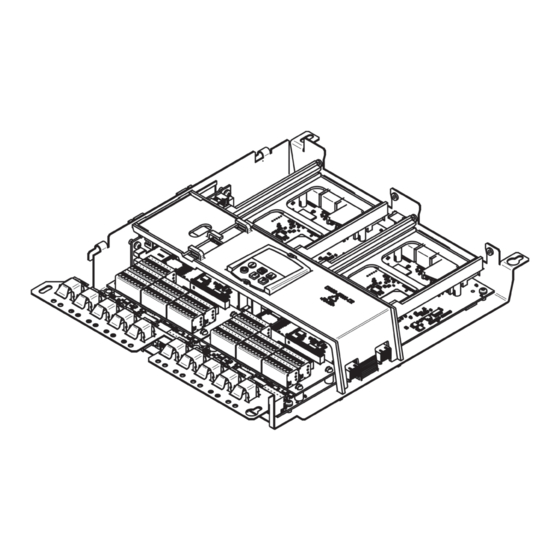
Their compact design makes them particularly easy to service and maintain since individual components are readily accessible. All SINAMICS DCM units are equipped with a BOP20 “Basic operator panel” mounted in the converter cover. The BOP20 has a backlit two-line display area and 6 keys. It may be used to acknowledge faults, set parameters and read diagnostic information. -
Page 10: Rated Dc Current
“wired up” and changed by parameters. 2.3 Rated DC current • The rating plate of the SINAMICS DCM Base drive panel has the rated Armature current listed of the output rating for IEC DC I constant duty rating. - Page 11 DC I through DC IV rated at 40˚C • DC I — Continuous Duty without no overloads possible • DC II — Continuous rating with 150% overload for 60 seconds with a 15 minute cool down below base load current setting •...
-
Page 12: Expandable Functionality Using Sinamics Components
(continued) 2.4 Expandable functionality using SINAMICS components One of the many features of the SINAMICS DCM Base Drive is its ability to expand its functionality modularly through the use of coupling supplementary modules from the SINAMICS drives family to the DRIVE-CLiQ interface. Modules include digital, analog I/O, external encoder and communications options. -
Page 13: Base Drive Panel Catalog Numbers
All horsepower ratings above are calculated using the DC II continuous rating with 150% overload for one minute, the result is rounded down to the nearest NEMA DC motor horsepower rating. Amp ratings for the 6RA80 SINAMICS DCM Base Drives are based upon DC I continuous ratings with no overload capability. NOTE All SINAMICS DCM base drives are provided with the Advanced CUD and CBE20 cards installed. -
Page 14: Service
24-hours a day. To contact the Technical Support and Field Service groups, simply call: 1-800-333-PIC1 (7421) SINAMICS DCM Base Drive panel instructions (1500A - 2800A DC) •... -
Page 15: Option Part Numbers
TMC - Terminal Module Cabinet – G63 option (C98043-A7125-L1) 6RY18030AB05 A pulse encoder evaluation circuit is a standard component of the basic SINAMICS DCM DC Converter. The SMC30 only needs to be ordered in configurations requiring evaluation of a second pulse encoder. -
Page 16: Cud Kits
6RY1803-0AA25-0AA1 A6X30112025 Connector Board - coated 6RY1803-0GA20 Spare parts There are two types of Spare Parts for the SINAMICS DCM Base Drives: • Spare parts internal to the Converter • Spare parts external to the Converter Spare parts internal to the Converter... - Page 17 • Expand the Selection & Ordering heading near the bottom of the page • Hover the mouse over the link for the “-> SINAMICS DCM Spare Parts Selector Tool – v1.7” and right-click • Select Save Target as… and save the MS Excel file to your computer •...
- Page 18 Part Recommended Description 575V 690V 830V 950V number spare 1.50 Amp, 250V, 1600, 1500, 1500, 2200 MDL-1-1/2 Type MDL 2000, 2000, 1900 2200, 2600 2800 SINAMICS DCM Base Drive panel instructions (1500A - 2800A DC) •...
- Page 19 Control transformer (1CTR) Where Where Where Where used DCI used DCI used DCI used DCI rating rating rating rating Part Recommended Description 575V 690V 830V 950V number spare 250 VA, 240V AC 1600, 1500, 1500, 2200 A1TRCQ0C286 – secondary 2000, 2000, 1900 2200,...
- Page 20 Part Recommended Description 575V 690V 830V 950V number spare Suppressor, varistor type 1600, 1500, 1500, 2200 3RT19161BD00 – 127 - 240V 2000, 2000, 1900 2200, 2600 2800 SINAMICS DCM Base Drive panel instructions (1500A - 2800A DC) •...
- Page 21 WARNING If a SINAMICS DCM Base Drive panel was damaged during transport, it must not be connected up without first being repaired and tested by a qualified repair person. Non-observance of the safety instructions can result in death, severe personal injury or substantial property damage.
- Page 22 Open Chassis (IP00) Degree of protection Refer to dimension drawings in Section 6 Dimensions Weights (approx.) Lbs. Explanation at end of list of tables SINAMICS DCM Base Drive panel instructions (1500A - 2800A DC) •...
- Page 23 5.2 1500 - 2600A DC (2 and 4Q) Base Drive panels, 690V 3-Phase AC Rated Armature Supply Rated supply voltage 3-phase armature 690 (+10% / – 20%) Rated input current 1245 1660 2158 armature Fan type 3-phase 460V Air flow rate 2400 Fan noise level dB(A)
- Page 24 Open Chassis (IP00) Degree of protection Refer to dimension drawings in Section 6 Dimensions Weights (approx.) Lbs. Explanation at end of list of tables SINAMICS DCM Base Drive panel instructions (1500A - 2800A DC) •...
- Page 25 5.4 2200A DC (2 and 4Q) Base Drive panels, 950V 3 Phase AC Rated Armature Supply Rated supply voltage 3-phase armature 950 (+10% / – 20%) Rated input current 1826 armature Fan type 3-phase 460V Air flow rate 2400 Fan noise level dB(A) 75.6 Rated supply voltage field...
- Page 26 SINAMICS DCM Base Drive panel. IMPORTANT When SINAMICS DCM Base Drive panels are installed into enclosures, make sure the temperature inside does not exceed the (Operational Ambient Temperature) rating of 40 or 45º C depending on the unit size, otherwise de-rate the DC current rating per the table below.
-
Page 27: Applicable Standards
6) Requirements to achieve control stability The control stability (closed-loop PI control) is referred to the rated motor speed and applies when the SINAMICS DCM is in the warm operating condition. This is based upon the following pre-conditions: • Temperature changes of ±10° K. -
Page 28: Installation Information
CAUTION Failure to lift the SINAMICS DCM Base Drive panel in the correct manner can result in bodily injury and/or property damage. The SINAMICS DCM Base Drive panel must be lifted using suitable equipment and under the instruction of appropriately qualified personnel. -
Page 29: Base Drive Panel Outlines
Installation and dimensions 6.2 Base Drive panel outlines •... - Page 30 Notes Notes usa.siemens.com/drives SINAMICS DCM Base Drive panel instructions (1500A - 2800A DC) •...
-
Page 31: Base Drive Panel Schematics
The unit must always be operated with the standard front covers in place. The user is responsible for ensuring that the motor, SINAMICS DCM Base Drive panel and other devices are installed and connected up in accordance with the approved codes of practice of the country concerned and any other regional or local codes that may apply. - Page 32 7 Base Drive panel connections (continued) SINAMICS DCM Base Drive panel instructions (1500A - 2800A DC) •...
- Page 33 Base Drive panel connections 7.1 Base Drive panel schematics •...
-
Page 34: Control Connections Control Units (Cud)
7 Base Drive panel connections (continued) 7.2 Control connections control units (CUD) Block diagram with connection suggestion SINAMICS DCM Base Drive panel instructions (1500A - 2800A DC) •... -
Page 35: Control Units (Cud)
Terminal locations advanced and standard control unit DC (CUD) Advanced CUD Standard CUD C98043-A7100-L4 C98043-A7100-L3 Module C98043-A7100 — Control unit (CUD) C98043-A7100-L4 = Advanced CUD C98043-A7100-L3 = Standard CUD (Both CUD’s are shown with connector board C98043-A7125 installed) Base Drive panel connections 7.2 Control units (CUD) •... - Page 36 7 Base Drive panel connections (continued) 7.3 Control units (CUD) SINAMICS DCM Base Drive panel instructions (1500A - 2800A DC) •...
-
Page 37: Description Of Power / Control Terminals
All external connections to the SINAMICS DCM Base Drive panels, including power connections are made with compression type terminals on the drive. The user is responsible for installation of the motor, SINAMICS DCM Base Drive panel, transformer and other devices in accordance with the National Electric Code and other applicable local codes that cover such items as wire size, protective grounding, disconnects and short circuit protection. - Page 38 Terminal Connection values/remarks Possible settings Armature supply AC input Externally connected to incoming, customer supplied See SINAMICS DCM operating 3 Phase voltage supply instruction manual and additional files on converter Ground PE conductor DVD for detailed parameter See technical data, section 5 descriptions and settings.
- Page 39 3 Phase supply supplied 480 VAC, 3 Phase supply For guidance on commissioning the SINAMICS DCM Base Drive, please refer to both the Operating Instructions Manual and the List Manual for the SINAMICS DCM DC Converter. Both manuals are provided on the Documentation DVD that is shipped with each Base Drive.
- Page 40 Notes Notes usa.siemens.com/drives 7-10 SINAMICS DCM Base Drive panel instructions (1500A - 2800A DC) •...
- Page 41 Notes usa.siemens.com/drives 7-11 Base Drive panel instructions (1500A - 2800A DC) SINAMICS DCM •...
- Page 42 Notes Notes usa.siemens.com/drives 7-12 SINAMICS DCM Base Drive panel instructions (1500A - 2800A DC) •...
- Page 43 Notes usa.siemens.com/drives 7-13 Base Drive panel instructions (1500A - 2800A DC) SINAMICS DCM •...
- Page 44 All rights reserved Order No.: LDMN-00002-0317 Printed in USA © 2017 Siemens Industry, Inc. Subject to changes and errors. The information given in this document only contains general descriptions and/or performance features which may not always specifically reflect those described, or which may undergo modification in the course of further development of the products.