Motorola MTM800 Basic Service Manual
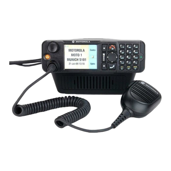
With enhanced control head tetra mobile terminal 380–430 mhz (mt912m) 410–470 mhz (mt512m)
Hide thumbs
Also See for MTM800:
- Feature user manual (382 pages) ,
- Product information manual (290 pages) ,
- Manual (254 pages)

Related Manuals for Motorola MTM800


Summary of Contents for Motorola MTM800
- Page 1 MTM800 with Enhanced Control Head TETRA Mobile Terminal 380–430 MHz (MT912M) 410–470 MHz (MT512M) Basic Service Manual Part Number: 6866539D28-D *6866539D28*...
-
Page 2: Copyright
Trademarks Motorola, the Motorola Logo and all other trademarks identified as such herein are trademarks of Motorola Inc. All other product or service names are the property of their respective owners. -
Page 3: Document History
DOCUMENT HISTORY DOCUMENT HISTORY The following major changes have been implemented in this manual since the previous edition:: Edition Description Date 6866539D28-A Initial Release Mar. 2007 6866539D28-B Changes in Accessories. Aug. 2007 Included info on MACE UCM Board Kit. 6866539D28-C Added GPS –... - Page 4 Notes...
- Page 5 These recommended RF exposure levels include substantial margins of protection. All Motorola 2-way terminals are designed, manufactured and tested to ensure they meet government-established RF exposure levels. In addition, manufacturers also recommend specific operating instructions to users of 2-way terminals.
-
Page 6: Federal Communications Commission Regulations (Us Markets Only)
RF exposure and to satisfy compliance requirements. Compliance with RF Exposure Standard Your Motorola terminal is designed and tested to comply with a number of national and international standards and guidelines (listed below) regarding human exposure to radio frequency electromagnetic energy. -
Page 7: Rf Exposure Compliance And Control Guidelines And Operating Instructions
40 to 110 Watts 90 cm (3 Ft) Note: If you are not sure of the rated power of your terminal, contact your Motorola representative or dealer and supply the terminal model number found on the terminal model label. If you cannot determine the rated power out, then assure 90cms (3 feet) separation from the body of the vehicle. -
Page 8: Approved Accessories
RF Safety Standards. Approved Accessories • This terminal has been tested and meets the RF Safety Standards when used with the Motorola accessories supplied or designated for this product. Use of other accessories may result in non- compliance with RF Safety Standards. -
Page 9: Facilities
Product Safety and RF Exposure Facilities To avoid electromagnetic interference and/or compatibility conflicts, turn off your terminal in any facility where posted notices instruct you to do so. Hospitals or health care facilities may be using equipment that is sensitive to external RF energy. Vehicles To avoid possible interaction between the terminal transmitter and any vehicle electronic control modules, such as, ABS, engine, or transmission controls, the terminal should be installed only by an... -
Page 10: Operational Warnings
viii Product Safety and RF Exposure OPERATIONAL WARNINGS W A R N I N G For Vehicles With Air Bags Do not mount or place a mobile terminal in the area over an air bag or in the air bag deployment area. -
Page 11: Additional Important Information
Dieses Gerät ist mit einer Schutzsicherung im Stromversorgungskabel ausgestattet. Bei Austausch ausschließlich den Originalwert verwenden WARNUNG: Bei Einsetzen von nicht vom Hersteller freigegebenen Ersatzteilen kann das Gerät zerstört werden. Sicherung für Stromversorgungskabel GKN6270/GKN6274: 10A (Motorola Best.-Nr.:65C80283E05) Sicherung für Zündungserkennungskabel HKN9327: 4A (Motorola Best.-Nr.:65C80283E02) - Page 12 Notes...
-
Page 13: Table Of Contents
CONTENTS CONTENTS COPYRIGHT Copyrights ............ii Computer Software Copyrights . - Page 14 CONTENTS CHAPTER 4 PROGRAMMING THE TERMINAL ......4-1 CHAPTER 5 TEST SETUP & TESTING Section Introduction .
-
Page 15: Contents
Further Assistance From Motorola ........ - Page 16 Notes...
-
Page 17: Scope Of This Manual
SCOPE & WARRANTY INFORMATION 1 - 1 CHAPTER 1 SCOPE & WARRANTY INFORMATION SCOPE OF THIS MANUAL This manual is intended for use by trained service technicians familiar with similar types of equipment only. It contains information required for the installation of the equipment described and is current as of the printing date. -
Page 18: Emea Manuals & User Guides
MTM800 with Enhanced Control Head Basic Service Manual (English) User Guides 6866539D24 MTM800 with Enhanced Control Head Basic User Guide (EN / DE / FR / ES / NL / AR) 6866539D34 MTM800 with Enhanced Control Head Basic User Guide (EN / RU / IT / PL) -
Page 19: Lacr Manuals & User Guides
MTM800 with Enhanced Control Head Basic Service Manual (English) User Guides 6866539D24 MTM800 with Enhanced Control Head Basic User Guide (EN / DE / FR / ES / NL / AR) 6866539D34 MTM800 with Enhanced Control Head Basic User Guide (EN / RU / IT / PL) -
Page 20: Warranty And Service Support
"return for repair" warranty, a check of the product should be performed prior to shipping the unit back to Motorola. This is to ensure that the product has been correctly programmed or has not been subjected to damage outside the terms of the warranty. -
Page 21: Chapter 2 Model Information & Accessories
MODEL INFORMATION & ACCESSORIES 2 - 1 CHAPTER 2 MODEL INFORMATION & ACCESSORIES MTM800 with Enhanced Control Head Mobile Terminal Model Information This manual applies to the following Mobile Terminal Models Type No. Sales Model No. Short Description Model MT512M... -
Page 22: Model Specifications
ETSi: ETS 300 394-1 Receiver Type: Superheterodyne Modulation Type: /4DQPSK Type Number: Frequency Range: RF Power: MTM800 ENH 410–470 MHz MT512M MTM800 ENH 380–430 MHz 3,16 W / 35 dBm MTM800 ENH 380–430 MHz MT912M MTM800 ENH 410–470 MHz 3,16 W / 35 dBm... -
Page 23: Model Descriptions
MODEL INFORMATION & ACCESSORIES 2 - 3 Model Descriptions** Model Description Dash Mount with Mobile Terminal with Direct Mount Enhanced Control Head, Speaker, Microphone or Handset, Standard User Guide, and Installation Accessories. Desk Mount with Mobile Terminal with Direct Mount Enhanced Control Head, Speaker, Microphone or Handset, Standard User Guide, Installation Accessories and Tray with power supply. -
Page 24: Accessories-To-Model Chart
2 - 4 MODEL INFORMATION & ACCESSORIES Accessories-to-Model Chart ACCESSORIES Control Heads Part Number Enhanced Control Head, English Keypad GMWN4298_ Enhanced Control Head, Chinese Keypad GMWN4299_ Enhanced Control Head, Korean Keypad GMWN4300_ Enhanced Control Head, Arabic Keypad GMWN4301_ Enhanced Control Head Bopomofu Keypad GMWN4302_ Enhanced Control Head Cyrillic Keypad GMWN4303_... - Page 25 MODEL INFORMATION & ACCESSORIES 2 - 5 ACCESSORIES Microphones Part Number Compact Fist Microphone RMN5107_ Heavy Duty Fist Microphone RMN5111_ Desktop Microphone, Mobile Microphone Port RMN5106_ Compact Fist, Mobile Microphone Port RMN5052_ Heavy Duty Fist Microphone, Mobile Microphone Port RMN5053_ Visor Microphone GMMN4065_ Loudspeakers...
- Page 26 2 - 6 MODEL INFORMATION & ACCESSORIES ACCESSORIES Junction Box Part Number Junction Box GMLN3002_ Cable 6m Transceiver to Junction Box GMKN4192_ Cable 4m Transceiver to Junction Box GMKN4193_ Cable 2m Transceiver to Junction Box GMKN4194_ Power Cables (to Mobile Terminal) Part Number 12V Power Cable to Battery, 3m with Fuse (10A) GKN6270_...
-
Page 27: Chapter 3 Overview
MTM800 with Enhanced Control Head. The process is called digital modulation. Digital Modulation Technique The MTM800 with Enhanced Control Head is a 380–430 or 410–470 MHz mobile that can operate in dispatch mode. It uses two digital technologies: π/4 DQPSK and Time Division Multiple Access (TDMA). -
Page 28: Voice Compression Technology
3 - 2 OVERVIEW Voice Compression Technology Voice is converted into a digital bit stream by sampling the voice at high rate and converting the samples into numbers, which are represented by bits. Voice compression reduces the number of bits per second while maintaining the voice at an acceptable quality level. -
Page 29: Chapter 4 Programming The Terminal
4 - 1 CHAPTER 4 PROGRAMMING THE TERMINAL Note: For programming the terminal, refer to TETRA Customer Programming Software (CPS) Start-up User Guide, Publication No. 6802974C10_. - Page 30 4 - 2 Notes...
-
Page 31: Test Setup & Testing
CHAPTER 5 TEST SETUP & TESTING Any level 3 repairs can deeply affect the performance of the MTM800 with Enhanced Control Head terminal and may cause a new tuning procedure. This tuning procedure can only be applied by certain authorized Motorola W A R N I N G depots where the appropriate TEST&TUNE EQUIPMENT is available. - Page 32 5 - 2 Notes...
-
Page 33: Chapter 5.1 Test Setup & Testing
TEST SETUP & TESTING for 380–430 MHz and 410–470 MHz Any level 3 repairs can deeply affect the performance of the MTM800 with Enhanced Control Head terminal and may cause a new tuning procedure. This tuning procedure can only be applied by certain authorized Motorola W A R N I N G depots where the appropriate TEST&TUNE EQUIPMENT is available. -
Page 34: Test Equipment
5.1 - 2 TEST SETUP & TESTING for 380–430 MHz and 410–470 MHz Test Equipment The table below lists the special test equipment required for servicing TETRA mobile terminals. Table 5.1-1 Test Equipment Name Part Number Digital Multimeter R1072_ 220V Power Supply R1011_/220V TETRA SVC MON. -
Page 35: Test Check List
TEST SETUP & TESTING for 380–430 MHz and 410–470 MHz 5.1 - 3 Test Check List The following table summarises the required test setups. Table 5.1-2 Test Setup Test Name Test Setup Terminal Setup Test Conditions Limits IFR System Setup Control Channel For 380–430MHz and Manual Test... -
Page 36: Receiver Tests
5.1 - 4 TEST SETUP & TESTING for 380–430 MHz and 410–470 MHz Table 5.1-2 Test Setup (Continued) Test Name Test Setup Terminal Setup Test Conditions Limits Call Processing 1KHz Test Signal Range 1 -90dBm Talk Back Group Mode Test Group 1 Call Processing Private Mode Private Mode... -
Page 37: Duplex Test
TEST SETUP & TESTING for 380–430 MHz and 410–470 MHz 5.1 - 5 Duplex Test 1. Digital Duplex Test (Tx) Measurement Capabilities: Bar chart display for Tx Power, Frequency Error, Vector Error RMS, Power Analyzer, Spectrum Analyzer, Vector Analyzer, Vector Diagrams. Configuration of the IFR 2968 System Setup The setup depends on the firmware version of the IFR 2968, the firmware version of the terminal and the customer programming of the terminal. - Page 38 5.1 - 6 TEST SETUP & TESTING for 380–430 MHz and 410–470 MHz k. Press the "Highest Channel" soft key and enter "1199" for 380 430MHz ("2799" – for 410 470MHz) using the data keys followed by the "Highest Channel" soft key. –...
- Page 39 TEST SETUP & TESTING for 380–430 MHz and 410–470 MHz 5.1 - 7 CIRCUIT MODE DATA SERVICE: SUPPORTED (RESERVED): NOT AVAILABLE SNDCP SERVICE: NOT AVAILABLE AIR INTERFACE ENCRYPTION: NOT AVAILABLE ADVANCED LINK: NOT SUPPORTED Note: The displayed values are factory defaults and should not be changed. 21.
-
Page 40: Configuration Of The Ifr 2968 Manual Test Screen
5.1 - 8 TEST SETUP & TESTING for 380–430 MHz and 410–470 MHz Configuration of the IFR 2968 Manual Test Screen The setup depends on the firmware version of the IFR 2968, the firmware version of the terminal and the customer programming of the terminal. The following procedure is only an example. -
Page 41: Rf Tests
TEST SETUP & TESTING for 380–430 MHz and 410–470 MHz 5.1 - 9 RF Tests Receiver Tests Simulate Base Station (registration) 1. Turn the terminal ON When the terminal is in Trunked Mode, continue with step 2. Otherwise perform steps a through c. -
Page 42: Transmitter Tests
5.1 - 10 TEST SETUP & TESTING for 380–430 MHz and 410–470 MHz Note: RSSI results will flash on the screen every few seconds. The display shows: SERV: 0/34348 RSSI: -90 CX: 20 CHQ: 99/E0 Disregard the “SERV”, “CX” and “CHQ” results. Actual RSSI measured =IFR RF Gen Level - Cable insertion loss +/- other stray losses. -
Page 43: Call Processing Test
TEST SETUP & TESTING for 380–430 MHz and 410–470 MHz 5.1 - 11 - Power Profile: Passed. - Burst Power Required Results: 33–37dBm. - Timing Error: < 0.25 symbols. - Vector Error: Max 10% RMS, Max 30% Peak, Max 5% Residual. - Frequency Error: +/- 100Hz. - Page 44 5.1 - 12 TEST SETUP & TESTING for 380–430 MHz and 410–470 MHz 2. Dial a random 4 digit number (eg "9359") using the alphanumeric keys of the terminal, press "Calltype" using the Lower (soft) key until "Phone #" is displayed and press the "Send"...
-
Page 45: Manual Mode Testing
TEST SETUP & TESTING for 380–430 MHz and 410–470 MHz 5.1 - 13 12. Press the “vector diagram” soft key. 13. View the following: - press “symbol constel” soft key for graphical symbol constellation. - press “rotated vector” soft key to zoom in on the constellation. - press “phase traject”... - Page 46 5.1 - 14 TEST SETUP & TESTING for 380–430 MHz and 410–470 MHz 9. Press any key again. The display shows "Keypad backlight is on". Verify that the keypad backlight is on. 10. Press any key to start the next test. The display shows "Emergency backlight test" 11.
-
Page 47: Service Flow Chart (Board Level)
Replace the costumer's radio Send the faulty radio to Level 3 maintenance Done Clone/reprogram customer details to new radio Send the TEI number of the new radio to the service provider. Figure 5.1-2 Servicing the MTM800 with Enhanced Control Head... -
Page 48: Fuses On The Mainboard
5.1 - 16 TEST SETUP & TESTING for 380–430 MHz and 410–470 MHz Fuses on the Mainboard C0301 F0301 C0336 C0159 C0151 F0302 C0157 VR0300 F0303 Fuses (Motorola R0311 C0328 Part Number: C0138 6580542Z01) C0337 C0325 U0304 Q0401 C0322 Q5804 Q0600... -
Page 49: Chapter 6 Maintenance
MAINTENANCE 6 - 1 CHAPTER 6 MAINTENANCE Introduction This chapter provides details about the following: • Preventive maintenance (inspection and cleaning) • Safe handling of CMOS and LDMOS devices • Pre-baking of Integrated Circuits • Repair procedures and techniques • Disassembly and reassembly of the terminal •... -
Page 50: Cleaning External Plastic Surfaces
6 - 2 MAINTENANCE CAUTION: The effects of certain chemicals and their vapors can have harmful results on certain plastics. Avoid using aerosol sprays, tuner cleaners, and other chemicals. Cleaning External Plastic Surfaces Apply the 0.5% detergent-water solution sparingly with a stiff, non-metallic, short-bristled brush to work all loose dirt away from the terminal. -
Page 51: Safe Handling Of Cmos And Ldmos Devices
• Ground the working surface of the service bench to protect the CMOS device. We recommend using the Motorola Static Protection Assembly (part number 0180386A82), which includes a wrist strap, two ground cords, a table mat, and a floor mat. -
Page 52: General Repair Procedures And Techniques
When damaged parts are replaced, identical parts should be used. If the identical replacement component is not locally available, check the parts list for the proper Motorola part number and order the component from the nearest Motorola Radio Products and Solution Organization listed in the “Piece Parts”... - Page 53 MAINTENANCE 6 - 5 Chip Components Use the RLN4062 Hot-Air Repair Station for chip component replacement. Adjust the temperature control to 390 °C (735 °F), and adjust the airflow to a minimum setting. Airflow can vary due to component density. •...
-
Page 54: Pre-Baking Of Integrated Circuits
If a reflow procedure takes place close to MS components the whole board must be pre-baked. Table 6-3 List of MTM800 with Enhanced Control Head moisture sensitive components Part. No. -
Page 55: Repair Procedures And Techniques - General
When damaged parts are replaced, identical parts should be used. If the identical replacement part is not locally available, check the parts list for the proper Motorola part number and order the part from the nearest Motorola Radio Products and Solution Organization listed in the “SUPPORT CENTRES”... -
Page 56: Terminal Disassembly And Reassembly - Detailed
6 - 8 MAINTENANCE Terminal Disassembly and Reassembly – Detailed The procedure to remove and replace a Enhanced Control Head, Top Cover or Transceiver Board is similar for all models of terminal. A typical procedure is therefore shown followed by specific disassembly procedures for Enhanced Control Heads, Remote Head Enhanced and Data Expansion Head Enhanced on terminal models. -
Page 57: Top Plastic Cover Removal
MAINTENANCE 6 - 9 Figure 6-2 Flexible Connection Removal Remove the flexible connection from the socket on the Enhanced Control Head board. Top Plastic Cover Removal Insert the dismantling tool in the middle of the terminal assembly side groove as shown in Figure 6-3. -
Page 58: Transceiver Board Removal
6 - 10 MAINTENANCE Transceiver Board Removal CAUTION: Some terminals are equipped with a GPS module at the left side bottom of the transceiver and/or an additional UCM Board inside the transceiver cover plate, refer to special label at the cover plate (dotted line at the figure below). There are flex cables installed connecting these boards to the main board. -
Page 59: Reassembly The Terminal Chassis And Transceiver Board
MAINTENANCE 6 - 11 CAUTION: The thermal pad can act as an adhesive and cause the leads of the heat dissipating devices to be over stressed if the board is lifted too quickly. If the board can't be easily lifted, the chassis must be heated up to 55 degree Celsius. GPS Cover GPS Cable GPS Board... -
Page 60: Enhanced Control Head - Disassembly
6 - 12 MAINTENANCE Fit the back housing to the Enhanced Control Head. Ensure that the tags on the back housing align with the snap catch grooves on the Enhanced Control Head. Press the back housing into place until it snaps into place. Check that the terminal chassis o-ring seal is undamaged and fitted in the groove on the chassis assembly. -
Page 61: Enhanced Control Head - Reassembly
MAINTENANCE 6 - 13 Press the dismantling tool until the snap connectors on the side of the back housing release from the Enhanced Control Head. ZWG0130215-O Figure 6-8 Enhanced Control Head Board Removal Remove the board from the Enhanced Control Head front housing by unscrewing the screws using a T10 TORX™... -
Page 62: Remote Head Enhanced - Disassembly
To Disassemble the Remote Head Enhanced from the Terminal: Remove the Remote Head Enhanced (PMLN4904_) from the Transceiver by inserting the dismantling tool (Motorola part number 6686119B01) in the recess between the Remote Head Enhanced and the Transceiver. To minimize cosmetic damage disassemble from the bottom side (label side). -
Page 63: Remote Head Enhanced - Reassembly
MAINTENANCE 6 - 15 Remote Back Housing Remote Head Enhanced Remote Back Head Figure 6-10 Remote Mount Enhanced Control Head with Remote Head Enhanced Remote Head Enhanced – Reassembly To Reassemble the Remote Head Enhanced: Connect the flex from the Remote Head Enhanced to the top small connector in the Trans- ceiver. -
Page 64: Remote Mount Enhanced Control Head - Reassembly
6 - 16 MAINTENANCE socket on the board. Remove the board from the Remote Mount Enhanced Control head front housing by stretching the Remote Mount Enhanced Control Head front housing and pulling up the board. Remove the keypad by gently pressing the keypad out from the Remote Mount Enhanced Control Head front housing. -
Page 65: Data Expansion Head Enhanced - Disassembly
MAINTENANCE 6 - 17 Data Expansion Head Enhanced – Disassembly CAUTION: The terminal must be disconnected from the power supply before commencing any disassembly. The Terminal Installation Manual should be referred to for more detailed information warnings and safety. To Disassemble the Data Expansion Head Enhanced from the Terminal Remove the Data Expansion Head Enhanced from the transceiver by inserting the dismantling tool (Part No. -
Page 66: Data Expansion Head Enhanced - Reassembly
6 - 18 MAINTENANCE To Disassemble the Connector Board from Expansion Head Housing Remove the silicon rubber frame Remove the four screws from the connector board. Remove all the protection caps on the front of the expansion head housing. Lift the connector board from the expansion head housing. Data Expansion Head Enhanced –... -
Page 67: Motorcycle Mount Enhanced Control Head - Disassembly
MAINTENANCE 6 - 19 Motorcycle Mount Enhanced Control Head – Disassembly To disassembly the Motorcycle Mount Enhanced Control Head: Unscrew the screws of the Motorcycle Mount Enhanced Control Head trunnion and remove the Motorcycle Mount Enhanced Control Head from the trunnion. Twist and pull out the telco cable from the connector. -
Page 68: Motorcycle Mount Enhanced Control Head - Reassembly
The following table lists the service aids recommended for working on the terminal. While all of these items are available from Motorola, most are standard workshop equipment items, and any equivalent item capable of the same performance may be substituted for the item listed. -
Page 69: Exploded Views & Parts Lists
MAINTENANCE 6 - 21 EXPLODED VIEWS & PARTS LISTS NOTE: For optimum performance, all replacement parts, diodes, transistors and integrated circuits must be ordered by Motorola part numbers. Transceiver Exploded View and Parts List – Figure 6-14 Transceiver Exploded View... - Page 70 6 - 22 MAINTENANCE Table 6-5 Transceiver Parts List Item No. Description Part Number Chassis (item 2 included) 2766532A01 Gasket, Enhanced Control Head 3202620Y01 Main PCB (items 4 – 7 included) refer to Appendix: Service Kits BNC Antenna Connector 0986166B01 Power Connector 0986165B01 Accessory Connector...
- Page 71 MAINTENANCE 6 - 23 UCM board inside the cover plate Figure 6-15 Location of additional UCM Board inside the Cover Plate CAUTION: There is a flex installed connecting the UCM board to the main board. Take extra care not to tear off the flex when dis-assembling or re-assembling the board from/to the transceiver cover plate or this could damage the UCM board and the main board.
-
Page 72: Enhanced Control Head - Exploded View And Parts List
6 - 24 MAINTENANCE Enhanced Control Head – Exploded View and Parts List ZWG0130201-O Figure 6-16 Enhanced Control Head – Exploded View 1 Table 6-6 Enhanced Control Head – Parts List 1 Item No Description Part No GCAI Cover 1515048C01 Keypad Assembly –... - Page 73 MAINTENANCE 6 - 25 11 11 ZWG0130201-O Figure 6-17 Enhanced Control Head – Exploded View 2 Table 6-7 Enhanced Control Head – Parts List 2 Item Item Description Part No Description Part No Main PWA Kit PMLN5226_ Front Housing Assembly 0104022J38 LCD Metal Retainer 4216900H01...
-
Page 74: Data Expansion Head Enhanced - Exploded View And Parts List
6 - 26 MAINTENANCE Data Expansion Head Enhanced – Exploded View and Parts List Figure 6-18 Data Expansion Head – Exploded View Enhanced Table 6-8 Data Expansion Head – Parts List Enhanced Item No Description Part No Expansion Head Housing 1564290B01 Cover 9 Sub-D 3864326B01... -
Page 75: Remote Mount Enhanced Control Head - Exploded View And Parts List
MAINTENANCE 6 - 27 Remote Mount Enhanced Control Head – Exploded View and Parts List Figure 6-19 Remote Mount Enhanced Control Head – Exploded View Table 6-9 Remote Mount Enhanced Control Head – Parts List Item No. Description Part No. Remote FFC (Main to Remote) 8471921L01 Remote PWA Kit... -
Page 76: Remote Mount Configuration - Exploded View And Parts List
6 - 28 MAINTENANCE Remote Mount Configuration – Exploded View and Parts List Remote Mount Cable Transceiver 10-Pin Connector Flex Remote Mount Enhanced Control Head Remote Head Enhanced Data Expansion Head Enhanced 10-Pin Connector Figure 6-20 Remote Mount Configuration – Exploded View Table 6-10 Associated Components for Remote Mount Configuration Description Part Number... -
Page 77: Motorcycle Mount Enhanced Control Head - Exploded View And Parts List
MAINTENANCE 6 - 29 Motorcycle Mount Enhanced Control Head – Exploded View and Parts List Figure 6-21 Motorcycle Mount Enhanced Control Head – Exploded View Table 6-11 Motorcycle Mount Enhanced Control Head – Parts List Item No. Description Part No. Side Cap Screw 0316960H02 MC Front Housing Assembly... - Page 78 6 - 30 Notes...
-
Page 79: Appendix A Replacement Parts & Kits
2 maintenance a transceiver board is replaced. The MTM800 mobiles are programmed at the factory. They cannot be tuned at the field service level. -
Page 80: Service Information
Aftermarket and Accessory Division (AAD). If no part number is assigned, the part is not normally available from Motorola. If a parts list is not included, this generally means that no user-serviceable parts are available for that kit or assembly. -
Page 81: Asia, Pacific Region
Aftermarket and Accessory Division (AAD). If no part number is assigned, the part is not normally available from Motorola. If a parts list is not included, this generally means that no user-serviceable parts are available for that kit or assembly. -
Page 82: Latin America Region
Bosques de Alisos #125 Col. Bosques de las Lomas CP 05120 Mexico DF 5252576700 Piece Parts: To order parts in Latin America and the Caribbean contact your local Motorola CGISS representative. MOTOROLA, INC. Latin American Countries Region 789 International Parkway... - Page 83 Some replacement parts, spare parts, and/or product information can be ordered directly. If a complete Motorola part number is assigned to the part, it is available from Motorola. If no part number is assigned, the part is not normally available from Motorola. If the part number is appended with an asterisk, the part is serviceable by Motorola Depot only.
-
Page 84: Service Kits
MTM800 ENH 380 UCM-M AES128 PMUE2882_S MTM800 ENH 380 UCM-M TEA1 AES128 PMUE2883_S MTM800 ENH 380 UCM-M TEA2 AES128 PMUE2884_S MTM800 ENH 380 UCM-M TEA3 AES128 PMUE2885_S MTM800 ENH 380 UCM-M GPS AES128 PMUE2886_S MTM800 ENH 380 UCM-M GPS TEA1 AES128... - Page 85 A - 7 Table 2 Service Kits-To-Model Chart (Continued) MTM800 Service Kits Description Part Number PMUE2894_S MTM800 ENH 380 UCM-M GPS TEA2 AES128 PMUE2895_S MTM800 ENH 380 UCM-M GPS TEA3 AES128 PMUE3270_S MTM800 ENH 380 UCM-M AES256 PMUE3271_S MTM800 ENH 380 UCM-M TEA1 AES256...
- Page 86 A - 8 REPLACEMENT PARTS & KITS Table 2 Service Kits-To-Model Chart (Continued) MTM800 Service Kits Description Part Number Chinese Keypad GMWN4305_ Korean Keypad GMWN4306_ Arabic Keypad GMWN4307_ BoPoMoFo Keypad GMWN4308_ Cyrillic Keypad GMWN4309_ English Keypad – Hungarian GMWN4606_ Motorcycle –English Keypad...
-
Page 87: Appendix B Product Specific Information
In case of blown fuses during the installation only replace those with identically value. Never insert different values. Fuse for Power Cable GKN6270/GKN6274: 10 A (Motorola Part Number: 6580283E05) Fuse for Ignition Sense Cable HKN9327: 4 A (Motorola Part Number: 6580283E02) -
Page 88: Spezielle Produktinformationen
HF-Leitung reduziert. Daraus kann sich eine Verringerung der Leistungsmerkmale des Gerätes ergeben. Sicherungen Sollte während der Installation die Sicherung durchbrennen, darf sie nur durch eine gleichwertige Sicherung ersetzt werden. Sicherung für DC Kabel GKN6270/GKN6274: 10 A (Motorola Bestellnummer: 6580283E05) Sicherung für Ignition Sense Kabel HKN9327: 4 A (Motorola Bestellnummer: 6580283E02)