HP Integrity BL860C i4 User's & Service Manual
Server blade
Hide thumbs
Also See for Integrity BL860C i4:
- Installation manual (28 pages) ,
- Instructions manual (10 pages) ,
- Firmware update manual (15 pages)
Table of Contents
Advertisement
Quick Links
Advertisement
Table of Contents
Troubleshooting

Related Manuals for HP Integrity BL860C i4


Summary of Contents for HP Integrity BL860C i4
- Page 1 HPE Integrity BL860c i4, BL870c i4 & BL890c i4 Server Blade User Service Guide Abstract This document contains specific information that is intended for users of this Hewlett Packard Enterprise product. Part Number: 5200-2523 Published: September 2017 Edition: 6...
-
Page 2: Revision History
Document Operating Supported Edition number Publication Date manufacturing systems product versions part number supported 5992–1083 HP-UX BL860c i4, BL870c First December 2012 i4 & BL890c i4 5900-2663 HP-UX BL860c i4, BL870c Second May 2013 i4 & BL890c i4 5900-2673... -
Page 3: Table Of Contents
Operating system is loaded onto the server blade............33 Operating system is not loaded onto the server blade.............33 OS login prompt....................... 33 Installing the latest firmware using HP Smart Update Manager..........34 Operating system procedures............. 35 Operating systems supported on the server blade..............35 Installing the operating system onto the server blade..............35... - Page 4 Blade link and system information parameters............. 75 Operating System Licenses.................. 76 The Quick Boot option...................77 Possible changes due to VC profile mapping on the upgraded blade server..77 Preserving VC-assigned MAC addresses in HP-UX by enabling Portable Image........................82 Troubleshooting..................84 Methodology..........................84 General troubleshooting methodology................
- Page 5 General diagnostic tools....................102 Fault management overview..................102 HP-UX Fault management..................... 102 Errors and error logs......................... 103 Event log definitions....................... 103 Event log usage......................103 iLO 3 MP event logs.......................104 SEL review........................105 Troubleshooting processors......................106 Processor installation order....................106 Processor module behaviors..................106 Enclosure information.......................
- Page 6 Using the saupdate command ..................133 Get mode......................133 Set mode......................134 Updating the firmware using saupdate ............135 Determining the Driver ID and CTRL ID.................135 Configuring RAID volumes using the ORCA menu-driven interface.........136 Creating a logical drive....................138 Deleting a logical drive....................139 Useful UEFI command checks..................141 UEFI............................141 UEFI Shell and POSSE commands................
- Page 7 W...............................163 Contents...
-
Page 8: Overview
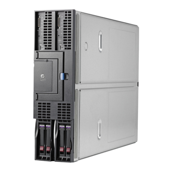
Overview The HPE Integrity BL860c i4 Server Blade is a dense, low-cost, Intel Itanium processor server blade. Using a Blade Link hardware assembly, multiple BL860c i4 Server Blades can be conjoined to create dual-blade, four socket and quad-blade, eight socket variants. -
Page 9: Server Blade Components
Server blade components CPU0 ICH mezzanine connector CPU0 power connector Mezzanine connector 3 (type 1 or 2) Mezzanine connector 1 (type 10 CPU1 power connector Mezzanine connector 2 (type 11 CPU1 1 or 2) System board thumbscrew 12 SAS backplane System board thumbscrew 13 Pull tab Battery (CR2032) -
Page 10: Site Preparation
Site preparation The BL860c i4 does not have cooling or power systems. Cooling and power is provided by the c-Class enclosure. IMPORTANT: To avoid hardware damage, allow the thermal mass of the product to equalize to the temperature and humidity of the installation facility after removing the shipping materials. A minimum of one hour per 10°C (50°F) of temperature difference between the shipping facility and installation facility is required. -
Page 11: Enclosure Environmental Specifications
• http://www.hpe.com/support/Bladesystem_c7000_Enclosures_Manuals For more site preparation information, go to http://www.hpe.com/info/Blades-docs, select HPE Integrity BL860c i4 Server Blade in the list of servers, and then select the Generalized Site Preparation Guidelines. Sample Site Inspection Checklist Table 3: Customer and Hewlett Packard Enterprise Information... - Page 12 Customer Information Secondary customer contact: Phone number: Traffic coordinator: Phone number: Hewlett Packard Enterprise information Sales representative Order number: Representative making survey Date: Scheduled delivery date Table 4: Site Inspection Checklist Check either Yes or No. If No, include comment number or date. Comment or Date Computer Room...
- Page 13 Check either Yes or No. If No, include comment number or date. Comment or Date Power and Lighting Number Area or Condition Are lighting levels adequate for maintenance? Are AC outlets available for servicing needs (for example, laptop)? Does the input voltage correspond to equipment specifications? 15a.
-
Page 14: Power Subsystem
Check either Yes or No. If No, include comment number or date. Comment or Date Can cooling be maintained between 5°C (41 °F) and 35°C (95 °F) (up to 1,525 m/5,000 ft)? Derate 1°C/305 m (34 °F/ 1,000 ft) above 1,525 m/5,000 ft and up to 3,048 m/10,000 Can temperature changes be held to 5°C (9 °F) per hour with tape media? Can temperature changes be held to 20°C (36 °F) per hour without tape media? -
Page 15: Esd Handling Information
ESD handling information CAUTION: Wear an ESD wrist strap when handling internal server components. Acceptable ESD wrist straps include: • The wrist strap that is included in the ESD kit with circuit checker (part number 9300-1609). • The wrist strap that is included in the ESD kit without circuit checker (part number 9300-1608). If the above options are unavailable, the throw away (one use only) strap that ships with some Hewlett Packard Enterprise memory products can also be used, with increased risk of electrostatic damage. -
Page 16: Unpacking The Server Blade
Unpacking the server blade Procedure 1. Use the instructions printed on the outside top flap of the carton. 2. Remove inner accessory cartons and the top foam cushions. IMPORTANT: Inspect each carton for shipping damage as you unpack the server blade. 3. -
Page 17: Installing The Server Blade Into The Enclosure
Configure iLO 3 MP access. Access iLO 3 MP. Access UEFI from iLO 3 MP. Download latest firmware and update using HP Smart Update Manager. Install and boot the OS. NOTE: For more information regarding HPE Integrity Server Blade upgrades, see Upgrading a conjoined configuration on page 59 for more information. -
Page 18: Removing A C7000 Device Bay Divider
2. Remove the three adjacent blanks. Removing a c7000 device bay divider Procedure 1. Slide the device bay shelf locking tab to the left to open it. 2. Push the device bay shelf back until it stops, lift the right side slightly to disengage the two tabs from the divider wall, and then rotate the right edge downward (clockwise). -
Page 19: Removing A C3000 Device Bay Mini-Divider Or Device Bay Divider
3. Lift the left side of the device bay shelf to disengage the three tabs from the divider wall, and then remove it from the enclosure. Removing a c3000 device bay mini-divider or device bay divider Procedure 1. Slide the locking tab down. Removing a c3000 device bay mini-divider or device bay divider... - Page 20 2. Remove the mini-divider or divider: a. c3000 mini-divider: Push the divider toward the back of the enclosure until the divider drops out of the enclosure. b. c3000 divider Push the divider toward the back of the enclosure until it stops. Slide the divider to the left to disengage the tabs from the wall.
-
Page 21: Installing Interconnect Modules
Installing interconnect modules For specific steps to install interconnect modules, see the documentation that ships with the interconnect module. Interconnect bay numbering and device mapping • HPE BladeSystem c7000 Enclosure • HPE BladeSystem c3000 Enclosure Installing interconnect modules... -
Page 22: Installing The Server Blade Into The Enclosure
To support network connections for specific signals, install an interconnect module in the bay corresponding to the embedded NIC or mezzanine signals. Server blade signal c7000 interconnect bay c3000 interconnect Interconnect bay labels NIC 1 (Embedded) NIC 2 (Embedded) NIC 3 (Embedded) NIC 4 (Embedded) Mezzanine 1 3 and 4... - Page 23 NOTE: Before installing and initializing the server blade, install any server blade options, such as an additional processor, hard drive, or mezzanine card. Procedure 1. Remove the connector covers if they are present. 2. Prepare the server blade for installation. 3.
-
Page 24: Server Blade Power States
The server blade should come up to standby power. The server blade is at standby power if the blade power LED is amber. Server blade power states The server blade has three power states: standby power, full power, and off. Install the server blade into the enclosure to achieve the standby power state. -
Page 25: Powering Off The Server Blade
For more information about iLO 3, see Using iLO 3 on page 29. Powering off the server blade Before powering down the server blade for any upgrade or maintenance procedures, perform a backup of critical server data and programs. Use one of the following methods to power off the server blade: NOTE: To power off blades in a conjoined configuration, only power off the Monarch blade. - Page 26 NOTE: If you will be upgrading an initial installation, see the user service guide for more information on server blade upgrades. Table 6: Blade Link bay location rules Class Number of Supported Blade location Partner blade Partner blade half- conjoined blades enclosures rules support?
- Page 27 Class Number of Supported Blade location Partner blade Partner blade half- conjoined blades enclosures rules support? height bay number / Server blade full- height bay number BL2E 2 (BL870c i4) c7000 only Bays 2&3, 4&5 Bottom half-height bay 9 or 6&7 with paired with full-height Monarch blade in bays 2&3, bottom half-...
- Page 28 Insert each adjacent blade, waiting 10 seconds between blades. NOTE: The blades will go into stand-by. Using the OA, verify that the rest of the blades that will be conjoined have an IP address and are powered off. Remove the plastic protectors from the connectors on the back of the Blade Link. Push in the blue release latch on the handle to release the handle.
-
Page 29: Using Ilo 3
IMPORTANT: The secondary UUID and other system variables are stored on the Monarch blade. If you do not put the Monarch blade in the leftmost slot, your system variables will not match. If you ever change your iLO 3 configuration (such as adding users) that data is also stored on the Monarch blade. -
Page 30: Uefi Front Page
Press Ctrl-C now to bypass loading option ROM UEFI drivers. 4. The prompt will timeout if Ctrl-C is not pressed within a few seconds. If Ctrl-C is pressed, you will be presented with two options: After selecting an option, boot will proceed. NOTE: If no option is selected, normal boot will proceed after ten seconds. - Page 31 To view boot options, or launch a specific boot option, press B or b to launch the Boot Manager. Installing the server blade into the enclosure...
- Page 32 To configure specific devices, press D or d to launch the Device Manager. This is an advanced feature and should only be performed when directed. To perform maintenance on the system such as adding, deleting, or reordering boot options, press M or m to launch the Boot Maintenance Manager.
-
Page 33: Saving Uefi Configuration Settings
35. • To load the OS using HP Ignite-UX, see Installing the OS using Ignite-UX on page 36. OS login prompt If your server blade is at the OS login prompt after you establish a connection to the server blade, use your standard OS log in procedures, or see your OS documentation for the next steps. -
Page 34: Installing The Latest Firmware Using Hp Smart Update Manager
Installing the latest firmware using HP Smart Update Manager The HP Smart Update Manager (HP SUM) utility enables you to deploy firmware components from either an easy-to-use interface or a command line. It has an integrated hardware discovery engine that discovers the installed hardware and the current versions of firmware in use on target servers. -
Page 35: Operating System Procedures
Operating system procedures Operating systems supported on the server blade HP-UX 11i v3 HWE 1209 Installing the operating system onto the server blade The following procedures describe generalized operating system installation. For more details, see the operating system documentation. Installing the OS from an external USB DVD device or tape device NOTE: Tapeboot requires BL8x0c i4 system firmware bundle 42.06 or later and a partner tape blade, or an... -
Page 36: Installing The Os Using Ignite-Ux
6. The OS now starts loading onto the server blade. Follow the on-screen instructions to install the OS fully. 7. Continue with Configuring system boot options on page 37 Installing the OS using Ignite-UX Ignite-UX is an HP-UX administration toolset that enables: • Simultaneous installation of HP-UX on multiple clients •... -
Page 37: Installing The Os Using Vmedia
To boot HP-UX, use one of the following procedures: • To boot HP-UX normally, see HP-UX standard boot on page 38. HP-UX boots in multi-user mode. • To boot HP-UX in single-user mode, see Booting HP-UX in single-user mode on page 40. -
Page 38: Adding Hp-Ux To The Boot Options List
For example, enter fs2: to access the UEFI System Partition for the bootable file system number2. The UEFI Shell prompt changes to reflect the file system currently accessed. The full path for the HP-UX loader is \EFI\HPUX\HPUX.EFI and it should be on the device you are accessing. -
Page 39: Booting Hp-Ux From The Uefi Boot Manager
Booting HP-UX from the UEFI Boot Manager Procedure 1. From the UEFI Boot Manager menu, choose an item from the boot options list to boot HP-UX. 2. Access the UEFI Boot Manager menu for the server on which you want to boot HP-UX. -
Page 40: Booting Hp-Ux In Single-User Mode
Procedure 1. Log in to HP-UX running on the server that you want to shut down or log in to iLO 3 MP for the server and use the Console menu to access the system console. Accessing the console through iLO 3 MP enables you to maintain console access to the server after HP-UX has shut down. -
Page 41: Optional Components
Installing the Blade Link for BL860c i4, BL870c i4 or BL890c i4 configurations on page 25. NOTE: SAS tape boot is now supported with tape blades on HPE Integrity BL860c i4, BL870c i4, and BL890c i4 server blades. NOTE: PCIe Gen-1 (driven from the ICH10 on the monarch blade’s ICH mezzanine card) provides the... - Page 42 NOTE: For a list of supported disk drives for the server blade, see: Server blade components list on page 109. Procedure 1. Remove the hard drive blank. 2. Prepare the hard drive. 3. Slide the drive into the cage until it is fully seated. 4.
-
Page 43: Installing Internal Components
Installing internal components Removing the access panel Procedure 1. Lift the access panel latch. 2. Slide the access panel backwards approximately 2 cm (0.75 in). 3. Remove the access panel by lifting it straight up and off the server blade. After the access panel is off, you can do the following: •... - Page 44 CAUTION: To avoid damage to the processor, handle the processor only by the edges. Do not touch the bottom of the processor, especially the contact area. CAUTION: To prevent possible server blade malfunction and damage to the equipment, multiprocessor configurations must contain processors with the same part number. The processor and heatsink ship as two separate units and are coupled together during installation into the server blade.
- Page 45 4. Remove the heatsink cover. CAUTION: During installation, after removing the protective cover from the heatsink: • Do not touch or come into contact with the thermal interface material. • Immediately install the heatsink. CAUTION: To avoid damage to the server blade and processor, ensure the processor heatsink locking handle is fully back against the stops, rotated about 120°...
- Page 46 CAUTION: To prevent thermal instability and damage to the server blade, do not separate the processor module from the processor's heatsink after they have been coupled. 6. Secure the heatsink to the processor a. Slide both plastic locking tabs into place. (See callout 1 in the following figure). b.
- Page 47 NOTE: Positive engagement clicking should occur during mating of the processor heat sink and processor module onto the socket to ensure proper seating. 7. Connect the power cord. (See callout 3 in the previous figure). 8. Tie wrap the processor cable to the right tie point on the processor assembly. CAUTION: When the CPU is installed, dress all slack in the power cable to the connector end of the cable.
-
Page 48: Dimms
DIMMs DIMM installation guidelines Observe the following guidelines when installing memory: • Use only Hewlett Packard Enterprise low-profile (1.2 in.) DIMMs. IMPORTANT: DIMMs from other sources may adversely affect data integrity. • In a BL860c i4 Server Blade, memory is loaded in identical pairs. •... - Page 49 Anything below this minimum results in insufficient memory and a hang either during the HP-UX boot or during the I/O configuration for the Integrity BL8x0c i4 systems. For example, the minimum memory configuration for the BL860c i4 is 8GB, for the BL870c i4 is 16GB, and for the BL890c i4 is 32GB.
- Page 50 Figure 2: Mixed DIMM load order Table 7: DIMM pair load order CPU0 CPU1 CPU0 only — — — — — — — — — — — — Both CPUs loaded 1st — — — — — — — — —...
- Page 51 CPU0 CPU1 — — 10th — — 11th — — 12th — — DIMM quad load order rules Figure 3: DIMM quad load order Figure 4: Mixed DIMM load order Optional components...
- Page 52 Table 8: DIMM quad load order CPU0 CPU1 Both — — — — CPUs loaded — — — — — — — — — — — — — — — — — — — — NOTE: • If more than two DIMM types are installed in the BL870c i4 or BL890c i4 systems, the customer will receive a warning indicating that optimum interleaving is not possible and memory may be de-allocated.
- Page 53 NOTE: The server blade ships with at least two DIMMs installed in slots 3A and 4A. 7. Ensure the DIMM slot latches are open. 8. Align the DIMM's notch with the slot's notch. CAUTION: Use only Hewlett Packard Enterprise low profile DIMMs. DIMMs from other sources might adversely affect data integrity.
-
Page 54: Mezzanine Cards
Mezzanine cards Optional mezzanine cards enable additional network connectivity and provide Fibre Channel support. For mezzanine card locations, see Server blade components on page 9. Optional mezzanine cards are classified as Type I mezzanine cards and Type II mezzanine cards. The card type determines where it can be installed in the server blade: •... -
Page 55: Hpe Smart Array P711M Controller
4. Align the mezzanine connector on the option card with the mezzanine connector on the system board. 5. Press down on the connector to seat the card. CAUTION: To prevent damage to the server blade, apply pressure over the mezzanine connector when installing the mezzanine card. -
Page 56: Supercap Pack Mounting Kit
NOTE: When a mixed configuration of BL860c i4, BL870c i4, and BL890c i4 server blades and other c- Class server blades is in the same enclosure, the preferred location for the P711m cards is slot 3. Supercap pack mounting kit The Smart Array P711m Controller includes a cabled Supercap Pack which mounts inside the server using the orderable AM341A Mounting Kit for Low profile battery (Hewlett Packard Enterprise part number AD399-2132A KIT, RAID BATTERY HOLDER). -
Page 57: Installing The P711M Controller Board
NOTE: Mezzanine slot 1 must contain the P711m Controller, another mezzanine card, or the mezzanine card blank. If you are installing the P711m card in mezzanine slot 1, do so now following the instructions “Installing the P711m Controller Board.” If you are not installing the P711m card in mezzanine slot 1, and no other mezzanine card is present in slot 1, then install the mezzanine card blank at this time. -
Page 58: Installing The Supercap Pack
Slot 1 Slot 2 Slot 3 NOTE: When a mixed configuration of BL860c i4, BL870c i4, and BL890c i4 server blades and other c- Class server blades are in the same enclosure, the preferred location for the P711m cards is slot 3. Use the procedure for installing standard mezzanine cards to install the SAS controller board, see Mezzanine cards on page 54 for more information. -
Page 59: Replacing The Access Panel
1. Position the Supercap Pack with the print side down and push the end of the cable that is connected to the Supercap Pack under the mounting bracket’s C-hook, routing the cable so its supercap end is on the side of the hook that is away from slot 3. 2. -
Page 60: Procedure Summary
Warranty and support are arranged to be transferred from the server being upgraded to the upgraded server. Upgrade kit contents • The HPE Integrity BL860c i4, BL870c i4 & BL890c i4 Server Blade Upgrades Read Me First. • One of the following Upgrade Blade Links: ◦... -
Page 61: Before Getting Started
Supported operating systems HP-UX 11i v3 OE Update for September 2012 IMPORTANT: If you will be using HP-UX, review the HP-UX errata documentation that is listed at http:// www.hpe.com/info/Blades-docs. Minimum firmware versions A minimum set of firmware is required for the blades and blade enclosures involved in the upgrade. -
Page 62: Determining Your Current Firmware Revisions
Product Name(s) Minimum Firmware Version Minimum Firmware Location HPE Integrity BL860c i4 Server T42.02 Go to http://www.hpe.com —> Blade Support & Drivers —> enter product name —> select HPE Integrity BL870c i4 Server operating system —> “Cross Blade operating system”... - Page 63 4. Compare the first four Revisions lines with the version information listed in the release notes at http:// www.hpe.com for the current server blade, HP Smart Update Manager firmware bundle. If any of the firmware revisions are less than those in the release notes, then the server firmware must be updated.
- Page 64 Spare Part No.: 503826-001 Serial Number : OB12BP7320 UUID : 09OB12BP7320 Manufacturer : HP Firmware Ver. : 3.60 Jun 11 2012 Hw Board Type : 0 Hw Version : B1 Use one of the following methods to determine the current VCM firmware version: OA GUI —...
- Page 65 VC Support Utility — Launch VC Support Utility – Interactive and enter version. ----------------------------------------------------------------------------- HP BladeSystem c-Class Virtual Connect Support Utility Version 1.7.0 (Build 95) Build Date: Oct 13 2010 07:03:49 Copyright (C) 2007-2010 Hewlett-Packard Development Company, L.P. All Rights Reserved ----------------------------------------------------------------------------- Please enter action ("help"...
-
Page 66: Rules For Server Blade Internal Components
USE827CYVC Module not present Not available ----------------------------------------------------------------------- USE827CYVC HP VC 8Gb 24-Port FC 1.03 v6.1.0_49 Module ----------------------------------------------------------------------- USE827CYVC HP VC 8Gb 24-Port FC 1.03 v6.1.0_49 Module ----------------------------------------------------------------------- USE827CYVC HP 1/10Gb VC-Enet Module 3.15 2010-10-09T07:18:16Z ----------------------------------------------------------------------- USE827CYVC HP 1/10Gb VC-Enet Module 3.15 2010-10-09T07:18:16Z... -
Page 67: Upgrading The Original Server
OS. For information on launching the OS from the UEFI shell, refer to UEFI Front Page on page 30. 2. If the Monarch Server is a HP Virtual Machines (VM) host with active guests or a Virtual Services Platform (VSP) with active Virtual Partitions (vPars), then either stop those guests or vPars now or migrate them to a temporary host server. - Page 68 IMPORTANT: Existing servers other than the Monarch Server and also any Upgrade Blades must be placed into enclosure bays with higher numbers than those occupied by the Monarch Server. Transfer the Monarch Server label carrier card to the Upgrade Blade Link: a.
- Page 69 e. Place the label carrier card behind the trap door of the Upgrade Blade Link, but do not install the Upgrade Blade link at this time. f. Reapply the “Field Upgrade Only” label to the upgrade Blade Link, making sure not to cover the Blade Link handle.
- Page 70 This is just an example so actual version numbers may be different from what is shown. If an update is required, it may need to be completed using the HP SUM Force Install option for both the iLO 3 and system firmware bundles. HP SUM should detect the mismatch and set the Force Install option by default.
- Page 71 (secondary). Below is an example of the output when upgrading from a BL860c i4 to a BL870c i4. [ilo002264fee1be] CM:hpiLO-> sysset SYSSET Current System Information Parameters: Manufacturer : HP Product Name (prodname) : Integrity BL870c i2 Secondary Product Name : Integrity BL860c i2 Product Number (prodnum) : AM358A...
- Page 72 Manufacturer : HP Product Name (prodname) : Integrity BL860c i4 Secondary Product Name : Integrity BL860c i4 Product Number (prodnum) : AM377A Secondary Product Number : AM377A Serial number (serial) : SGH2101LRY Secondary serial number : SGH2101LRY UUID (uuid) : 59F30FC7-8A4A-11E1-AF3F-DC6163A31240...
- Page 73 VC server profile match what is required. See Possible changes due to VC profile mapping on the upgraded blade server on page 77 for more information. If the HP-UX Portable Image tool is used (see Preserving VC-assigned MAC Optional components...
-
Page 74: Final Hardware Check
HP-UX by enabling Portable Image on page 82), then it’s best not to make changes until after the entire upgrade is completed and any changes then should be made very carefully. Once assigned, verify that there are no errors indicated by VCM or by the OA. Any VCM Domain Status or OA System Status alerts or warnings should be resolved before proceeding. -
Page 75: Support
4. If the Monarch Server is an HPVM host server or a Virtual Services Platform (VSP), then the VM guests or vPars can now be migrated back or started if they were stopped. Refer to the HP Integrity VM or vPar Administrator Guides document for information regarding guest and vPar migration. Test each VM guest or vPar to make sure each is functioning properly. -
Page 76: Operating System Licenses
Product Number. Operating System Licenses HP-UX requires a License to Use (LTU) for each processor (socket) installed in a server and HP-UX uses tiered licensing levels based on the maximum processor socket count of the server it runs on. The tier level will rise when the upgraded server contains more sockets than the original Monarch Server. -
Page 77: The Quick Boot Option
The HP-UX license is delivered physically or electronically by certificate. To contact your Hewlett Packard Enterprise sales representative for more information about software licensing agreements, go to http:// www.hpe.com/contact. The Quick Boot option The ability to scale up a blade server by adding more blade level resources is inherent to the BL8x0c architecture. - Page 78 Connect for c-Class BladeSystem User Guide for more information on VCM server profiles. The only caution is that if you use the PI tool (more on that follows), then you must let HP-UX boot with the profile untouched and disable PI before making changes to the profile.
- Page 79 The WWN is assigned in this example by VCM (as opposed to using HW default WWNs) so the WWN does not change, but the HW path as seen by HP-UX is different so this would be seen as a new device.
- Page 80 Profile entry Assigned SAN VCM assigned WWN Mapping to BL870c i4 ports unassigned 50:06:0B: Auxiliary MEZZ1:1-b 00:00:C3:26:1C unassigned 50:06:0B: Auxiliary MEZZ1:2-b 00:00:C3:26:1E SAN-5 50:06:0B: Monarch LOM:3-b 00:00:C3:26:20 The Monarch blade LOM3 now has the correct SAN assignment so the HW path from the original server has been restored, but the WWN is changed so a change to the SAN infrastructure may be necessary so that the required storage devices associate with the new WWN.
- Page 81 Profile entry Assigned network VCM assigned Mapping to Mapping to MAC address BL860c i4 ports BL870c i4 ports LAN-1 00-17-A4-77-90-10 Monarch LOM1–a Monarch LOM1–a LAN-2 00-17-A4-77-90-12 Monarch LOM2–a Auxiliary LOM1–a LAN-3 00-17-A4-77-90-14 Monarch LOM3–a Monarch LOM2–a LAN-4 00-17-A4-77-90-16 Monarch LOM4–a Auxiliary LOM2–a LAN-5 00-17-A4-77-90-18 Monarch LOM1–b...
-
Page 82: Preserving Vc-Assigned Mac Addresses In Hp-Ux By Enabling Portable Image
Preserving VC-assigned MAC addresses in HP-UX by enabling Portable Image If your OS is HP-UX where the VC server profile does not use the hardware default MAC addresses and it is important that Ethernet connections configured in the OS retain their VC-assigned MAC addresses, then there is a package called “Portable Image”... - Page 83 3. The networking should be checked to make sure that the original system network instances function correctly. If the HP-UX boot reports a LAN interface configuration failure, then check the /etc/rc.log file for the failed instance number which may indicate something like the following example:...
-
Page 84: Troubleshooting
Troubleshooting Cause This chapter provides strategies, procedures, and tools for troubleshooting server blade error and fault conditions. Methodology General troubleshooting methodology Procedure 1. Review the following list of symptoms: a. Front Panel LED blinking b. System messages on the OA c. - Page 85 L - Live Events Enter menu item or [Ctrl-B] to Quit: e Log Name Entries % Full Latest Timestamped Entry ---------------------------------------------------------------------- --------- E - System Event 489 18 % 03 Jan 2001 00:11:17 Event Log Navigation Help: + View next block (forward in time, e.g. from 3 to 4) - View previous block (backward in time, e.g.
-
Page 86: Executing Recommended Troubleshooting Methodology
For information on LED locations and states, see Front panel LEDs on page 94. • The SEL provides detailed information about the errors identified by the LEDs. For server alerts of levels 3-5, the attention condition on the server LED can only be cleared by cycling DC power. -
Page 87: Basic And Advanced Troubleshooting Tables
Basic and advanced troubleshooting tables Use the following troubleshooting tables to determine the symptoms or condition of a suspect server blade. The state of the front panel LEDs can be viewed locally. NOTE: Virtual front panel LEDs in the iLO 3 TUI are not the same as the front panel LEDs, see Virtual Front Panel LEDs in the iLO 3 TUI on page 98 for more information about Virtual front panel LED troubleshooting. - Page 88 Step Condition Action Blade health LED is off and iLO 3 LED is A fatal fault has been detected and logged while flashing amber or off. booting or running system firmware (SFW or iLO 3 firmware). 1. Cannot access the iLO 3 MP at this time. 2.
- Page 89 Step Condition Action Cannot find a boot disk. The iLO 3 MP is Nothing can be logged for this condition. running. 1. Check the disk drive LED. 2. Examine the Smart Array POST message. 3. If FC storage is used for boot, check the FC card status with the offline utility (drvcfg).
- Page 90 Step Condition Action "SYSVARS_MISMATCH" - The system Use the sysset command. variable stored on the Blade Link does not match the system variable stored on the blade. "SBL_DOMAIN_IMPROPER_SBL" - The 1. Be sure that the Blade Link installed in the correct slot and enclosure, see Installing the Blade Link currently installed is not Blade Link for BL860c i4, BL870c i4 or...
- Page 91 Table 11: Advanced Low End Troubleshooting Step Symptom/Condition Action Cannot read SEL from the SEL logging has stopped (health is steady green and power system console. is steady green). Examine console messages for any UEFI errors or warnings about operation or communications. This issue is fixed when the SEL resumes logging.
-
Page 92: Troubleshooting Tools
This issue is fixed when the MCA does not repeat. Troubleshooting tools Cause The HPE Integrity BL860c i4 Server Blade uses LEDs and other tools to help troubleshoot problems that occur in the server blade. Controls and ports Troubleshooting tools... -
Page 93: Front Panel View
Front panel view Monarch blade indicator HDD bay 2 UID LED Blade power LED Blade health LED Partition Identifier NICs 1, 2, 3, 4 10 Physical Presence Button Monarch power button SUV connector HDD bay 1 Rear panel view Front panel view... -
Page 94: Server Blade Leds
Power connectors GBX signal connectors Server blade LEDs Front panel LEDs Item Description Status Monarch blade indicator Green = Blade is acting as Monarch blade Off = Blade is not Monarch or is not conjoined UID LED Blue = Identified Blue flashing = Active remote management Off = No active remote... -
Page 95: Sas Disk Drive Leds
Item Description Status NICs 1, 2, 3, 4 Green = Network linked Green flashing = Network activity Off = No link or activity Monarch power button / Monarch Green = Blade is acting as power LED Monarch and is powered on Amber = Blade is acting as Monarch and is in standby Off = Blade is not Monarch... -
Page 96: Sas Hard Drive Led Combinations
SAS hard drive LED combinations NOTE: Predictive failure alerts only occur when the hard drive is connected to a Smart Array controller. Table 12: SAS disk drive LEDs: RAID mode Online/activity LED (green) Fault/UID LED (amber/blue) Interpretation On, off, or flashing Alternating amber and blue The drive has failed, or a predictive failure alert has been... - Page 97 Online/activity LED (green) Fault/UID LED (amber/blue) Interpretation Flashing irregularly Amber, flashing regularly (1 Hz) The drive is active, but a predictive failure alert has been received for this drive. Replace the drive as soon as possible. Flashing irregularly The drive is active, and it is operating normally.
-
Page 98: Blade Link Leds
Blade Link LEDs Description Status Busy LED Green = Blade Link is currently active. Do not remove. Off = Blade Link is not currently active. Safe to remove. Virtual Front Panel LEDs in the iLO 3 TUI iLO 3 has no LED that equates to the Blade Health LED located on the front panel of each individual BL860c i4 Server Blade. - Page 99 Table 14: Indications for the iLO 3 TUI LEDs VFP LED Purpose Equivalent Indications Value HEALTH Represents the System Health LED in the Flashing Health of the partition and the health of the entire iLO 3 GUI's Virtual Front amber health of one or more blades system/partition.
-
Page 100: Suv Cable And Ports
every blade in the Steady green System is beginning to boot System Health page in partition. the OS. the iLO 3 GUI OS is not booting and there There is no physical LED are no fatal events. on the blade's front panel that represents this state. -
Page 101: Connecting To The Serial Port
CAUTION: The SUV cable is not designed to be used as a permanent connection. Use caution when walking near the server blade when the SUV cable is installed. Hitting or bumping the cable might cause the port on the server blade to break. This can damage the system board. Server blade USB ports (2) Video... -
Page 102: Diagnostics
If the OS cannot be booted, use the offline support tools to resolve the issue. The offline support tools are available from the UEFI partition. after you resolve the issue preventing booting, boot HP-UX, and use the online support tools for any further testing. -
Page 103: Errors And Error Logs
HPE SMH is the application used to query information about monitored devices and view indications and instances on WBEM. This WBEM-based network management application enables you to create subscriptions and view indications. SysMgmtPlus functionality displays the property pages of various devices and firmware on SMH. SysMgmtPlus allows SMH to display improved property pages that contain dynamic content, providing the user to view and hide details of devices and firmware. -
Page 104: Ilo 3 Mp Event Logs
Enter menu item or [Ctrl-B] to Quit: System Event (E) and Forward Progress (F) logs are useful to determine the context of an error. iLO 3 MP event logs The iLO 3 MP provides diagnostic and configuration capabilities. For more information on the iLO 3 MP commands, see the HPE Integrity and HPE 9000 Integrated Lights-Out Management Processor Operations Guide. -
Page 105: Sel Review
e. Live Events f. Clear SELs 5. Enter Ctrl–B to return to the MP Main Menu. SEL review Procedure 1. Access the iLO 3 MP command prompt. 2. Run the sl command. The Event Log Viewer menu displays: [fp10mp]</>hpliLO-> sl Event Log Viewer Menu: Log Name Entries... -
Page 106: Troubleshooting Processors
4080231200E10008 0000000000000000 FW_UPDATE_SUCCESS 07 Jan 2010 22:40:43 4080236800E10006 0000000000000000 FW_UPDATE_SIG_OVERRIDE 07 Jan 2010 22:33:05 4080230D00E10004 0000000000000000 FW_UPDATE_START 07 Jan 2010 22:31:23 408022E200E10002 0000000000000000 ENTER_MFG_MODE 4. Select a, then a threshold filter number to filter events to desired level. MP:SL (+,-,<CR>,D, F, L, J, H, K, T, A, U, ? for Help, Q or Ctrl-B to Quit) >a Alert Level Threshold Filter: : Major Forward Progress... -
Page 107: Firmware
SUV cable. The MP LAN connection can be made via the network or OA. HP-UX uses the RS-232 serial text connection to a dumb terminal, or to terminal emulator software running on a PC, to control server blade operations locally. All other connections are unsupported. -
Page 108: Troubleshooting The Environment
HP-UX alternatively uses the MP 10/100 BT LAN connection over a private network, to control one or more server blade operations locally through telnet or SSH, or remotely over a public network through a web GUI. NOTE: RS-232 connection: If a dummy terminal/PC running terminal emulation software is attached to the iLO 3 MP local port and does not respond to a Ctrl–B key sequence then it is possible that the iLO... -
Page 109: Removing And Replacing Components
Removing and replacing components Server blade components list NOTE: Part numbers are found by using the part nomenclature from this list to select the correct part from Hewlett Packard Enterprise Partsurfer (http://partsurfer.hpe.com/). Table 16: CRU List Description with Part Number Spare Part Number Memory DIMM,4GB PC3L-10600R,512Mx4,RoHS (Old type) - Page 110 DIMM 16GB PC3L-10600R 512Mx4 RoHS (New type) 739928-001 Processors Intel Itanium 9520 Four Core processor - 1.73Ghz (part AT085-69023 number AT085-2019A) Intel Itanium 9550 Four Core processor - 2.40Ghz (part AT085-69024 number AT085-2020A) Intel Itanium 9540 Eight Core processor - 2.13Ghz (part AT085-69025 number AT085-2021A) Intel Itanium 9560 Eight Core processor - 2.53Ghz (part...
- Page 111 HPE BLc NC551m DP FlexFabric Adptr Opt 580238-001 (part number 580151-B21) HPE SA P711M/1G PMC based Controller 537156-001 (part number 513778-B21) HPE 4X QDR IB CX-2 Dual Port Mezz HCA 593411-001 (part number 592519-B21) HPE BLc NC360m NIC Adapter Opt Kit (part 615319-001 number 445978-B21) HPE BLc NC364m NIC Adapter Opt Kit (part...
-
Page 112: Preparing The Server Blade For Servicing
AM377-6901A BL8x0c i4 Base Unit (part number AM377-2001A) SAS disk backplane (part number AD399-67009 AD399-60009) System battery — Smart Array battery — Front bezel — Description with Part Number Spare Part Number SAS Hard Drive Blank — System Chassis (part number AD399-2102F) AD399-2102F CPU Heatsink (part number AD399-2120D) 612269-001... -
Page 113: Powering Off The Server Blade
CAUTION: Electrostatic discharge can damage electronic components. Ensure you are properly grounded before beginning an installation procedure. For more information, see the ESD handling information on page 15. WARNING: Before proceeding with maintenance or service on a server blade that requires physical contact with electrical or electronic components, be sure that power is removed or safety precautions are followed to prevent electric shock and equipment damage. -
Page 114: Replacing The Blade Link For Bl870C I4 Or Bl890C I4 Configurations
Procedure 1. Power off the Monarch blade. (Preparing the server blade for servicing on page 112). 2. Push in the blue release latch on the handle to release it. 3. Pull the handle out to release the Blade Link. 4. Pull the Blade Link straight out, placing a free hand on the top right side of the bezel as you pull to provide a counterbalance. -
Page 115: Blade Link For Bl860C I4 Configurations
Push in the blue release latch on the handle to release the handle. Pull the handle all the way out. Align the guide pins on the back of the Blade Link to the holes on the front of the server blades. As you insert the pins into the holes, ensure the face on the Blade Link is evenly aligned parallel to the face of the server blades. -
Page 116: Server Blade
CAUTION: To prevent damage to the Blade Link, make sure that the activity light is off before proceeding. Procedure 1. Power off the server blade and remove it from the enclosure (Preparing the server blade for servicing on page 112). 2. -
Page 117: Access Panel
CAUTION: The enclosure fans might still be running when the server blade is in standby mode. Opening the lever removes all power from the server blade. Procedure 1. Power off the server blade. (Powering off the server blade on page 25) 2. -
Page 118: Disk Drive Blanks
3. Slide the access panel backwards approximately 2 cm (0.75 in). 4. Remove the access panel by lifting it straight up and off the server blade. To replace the component, reverse the removal procedure. Disk drive blanks The server blade has two disk drive bays. If you only purchased one hard disk, then your server blade has a hard drive blank installed. - Page 119 For the location of the SAS disk LEDs, see SAS disk drive LEDs on page 95. To assess hard drive status, observe the SAS disk drive status LEDs. For an explanation of these LEDs, see Front panel LEDs on page 94. IMPORTANT: Before removing a SAS disk drive, perform a complete data backup.
-
Page 120: Dimm Baffle
CAUTION: Populate hard drive bays with a SAS disk drive or a hard drive blank. Operating the server blade without a SAS disk drive or disk drive blank causes improper airflow and cooling, which can lead to thermal damage. To replace the component, reverse the removal procedure. DIMM baffle CAUTION: To avoid damage to the server blade and the enclosure, install the DIMM baffle in the proper... -
Page 121: Dimms
To replace the component, reverse the removal procedure. DIMMs The memory subsystem supports only DDR3 SDRAM technology using industry-standard 1.2” high DIMMs. Single BL860c i4 Min / BL870c i4 Min / Max BL890c i4 Min / Max DIMM sizes Max Memory Memory size Memory size size... -
Page 122: Cpu Baffle
IMPORTANT: DIMMs do not seat fully if turned the wrong way. To replace the component, reverse the removal procedure. IMPORTANT: Follow the DIMM installation guidelines when replacing or adding DIMMs (DIMMs on page 48). CPU baffle CAUTION: To prevent damage to the server blade, never power on a server blade without a CPU baffle or CPU in each CPU socket. -
Page 123: Cpu And Heatsink Module
To replace the component, reverse the removal procedure. CPU and heatsink module The BL860c i4 Server Blade contains a processor subsystem accommodating one or two Intel Itanium processor modules. Each processor module consists of the following: • CPU chip, including CPU cores, QPI links for CPU-CPU and CPU-IO Hub chip connections, and SMI links for CPU-Memory interface chip connections •... - Page 124 CAUTION: To prevent thermal instability and damage to the server, do not separate the CPU module from the heatsink. Procedure 1. Power off the server, and remove it from the enclosure (Preparing the server blade for servicing on page 112). 2.
- Page 125 7. If the CPU is not being replaced, install a CPU baffle ( CPU baffle on page 122). CAUTION: To avoid damage to CPU socket pins and ensure proper system cooling, install a CPU baffle in an empty CPU socket. The replacement CPU module is shipped from Hewlett Packard Enterprise without a heatsink.
-
Page 126: Sas Backplane
NOTE: After replacing the processor and heatsink module use the cpuconfig from UEFI to verify the that the processor socket has been reconfigured. SAS backplane The SAS disk backplane supports two small form factor hard disk drives. The backplane supports hot- plugging a single SAS drive at a time. -
Page 127: Mezzanine Cards
WARNING: The computer contains an internal lithium manganese dioxide, a vanadium pentoxide, or an alkaline battery pack. A risk of fire and burns exists if the battery pack is not properly handled. To reduce the risk of personal injury: • Do not attempt to recharge the battery. -
Page 128: Ich Mezzanine Board
To replace the component, reverse the removal procedure. ICH mezzanine board The ICH mezzanine card houses the following components: • Intel ICH10 South Bridge • ATI/AMD RN50/ES1000 Video Controller • Embedded TPM 1.2 • The internal USB port — NOT SUPPORTED FOR USE One ICH mezzanine board is required per server blade in the BL860c i4. -
Page 129: System Board
To replace the component, reverse the removal procedure. System board CAUTION: To prevent damage to the system board, do not remove the system board from the server blade. In the event of a system board failure, both the system board and the server blade are replaced. Before sending in the system board and server blade for replacement, remove the following components: •... -
Page 130: Blade Link
IMPORTANT: Replacement server blades are shipped with the RAID controller in HBA mode by default. If the server blade RAID controller was in RAID mode before replacement, you must change the mode using the saupdate utility before booting the OS. See Configuring a Smart Array Controller for instructions on using the saupdate utility. -
Page 131: Support And Other Resources
Hewlett Packard Enterprise Support Center More Information on Access to Support Materials page: www.hpe.com/support/AccessToSupportMaterials IMPORTANT: Access to some updates might require product entitlement when accessed through the Hewlett Packard Enterprise Support Center. You must have an HP Passport set up with relevant entitlements. Support and other resources... -
Page 132: Websites
Software Depot www.hpe.com/support/selfrepair Customer Self Repair www.hpe.com/info/insightremotesupport/docs Insight Remote Support www.hpe.com/info/hpux-serviceguard-docs Serviceguard Solutions for HP-UX www.hpe.com/storage/spock Single Point of Connectivity Knowledge (SPOCK) Storage compatibility matrix www.hpe.com/storage/whitepapers Storage white papers and analyst reports Customer self repair Hewlett Packard Enterprise customer self repair (CSR) programs allow you to repair your product. If a CSR part needs to be replaced, it will be shipped directly to you so that you can install it at your convenience. -
Page 133: Raid Configuration And Other Utilities
RAID configuration and other utilities Configuring a Smart Array Controller Using the saupdate command The saupdate command is used to query or change the mode of the Smart Array P410i and Smart Array P411 controllers to HBA or RAID. Querying or changing modes is not supported for other controllers. The following are the newly added commands to saupdate: •... -
Page 134: Set Mode
Set mode IMPORTANT: If you are using HBA mode, do not install any disk that has previously been a part of a RAID volume into the system. Use set_mode to change the mode of the controller. If the controller is already in the required mode the following message appears: The controller at <seg:bus:dev:func>... -
Page 135: Updating The Firmware Using Saupdate
IMPORTANT: After changing the mode, perform a reconnect-r command at UEFI. NOTE: Commands are not case-sensitive. Updating the firmware using saupdate Procedure 1. Download the firmware image file into the system's UEFI partition. 2. Boot the system to the UEFI Shell and change directories to the UEFI partition. 3. -
Page 136: Configuring Raid Volumes Using The Orca Menu-Driven Interface
3. Use the drvcfg command. 4. Find the SAS Host Bus Adapter’s Driver ID in the list, and make a note of the corresponding Ctrl ID. NOTE: If the drivers listing shows X under CFG and DIAG, the drive is in RAID mode and you can run drvcfg against it. - Page 137 The ORCA main menu will appear. The ORCA main menu contains the following options: • Create Logical Drive • View Logical Drive • Delete Logical Drive RAID configuration and other utilities...
-
Page 138: Creating A Logical Drive
NOTE: If you are configuring the Smart Array P700m/512 Controller or the HPE StorageWorks SB40c storage blade (P400 controller), then you can enter ORCA from POST by pressing the F8 key when prompted. Creating a logical drive Procedure 1. At the ORCA main menu, select Create Logical Drive. 2. -
Page 139: Deleting A Logical Drive
6. To save the configuration, press F8. 7. To acknowledge that the configuration was saved and return to the ORCA Main Menu, press Enter. Deleting a logical drive WARNING: Back up all necessary data before deleting the logical drive. When you delete a logical drive, data on the drive is not preserved. - Page 140 2. Select a logical drive to be deleted. 3. Press F3 to delete the logical drive. RAID configuration and other utilities...
-
Page 141: Useful Uefi Command Checks
4. To acknowledge that the configuration was saved and return to the ORCA Main Menu, press Enter. Useful UEFI command checks saupdate.efi list Use saupdate.efi list to list controller information such as the controller version. drivers Use drivers to find the driver version and DRV #. pci–i <path>... -
Page 142: Uefi Shell And Posse Commands
NOTE: Unified EFI Forum, Inc. defines the specification used to implement UEFI. POSSE is a Hewlett Packard Enterprise extension to UEFI, which provides a common user interface architecture to better serve Hewlett Packard Enterprise customers, service, and manufacturing. UEFI consolidates boot utilities similar to those found in PA-RISC based servers, such as the BCH, and platform firmware into a single platform firmware. - Page 143 UEFI Shell Command Definition connect Connects one or more UEFI drivers to a device Copies one or more files or directories to another location cpuconfig Deconfigure/Reconfigure processor sockets and threads date Displays or changes the current system date dblk Displays one or more blocks from a block device dbprofile Manage direct boot profiles default...
- Page 144 UEFI Shell Command Definition guid Displays all registered UEFI GUIDs help Displays the UEFI Shell command list or verbose command help hexedit Full screen hex editor Executes commands in specified conditions ifconfig Modify the default IP address of UEFI network stack info Display hardware information input...
-
Page 145: Drive Paths In Uefi
UEFI Shell Command Definition ping Ping a target machine with UEFI network stack reconnect Reconnects one or more UEFI drivers to a device reset Resets the system Deletes one or more files or directories salproc Make a SAL procedure call secconfig View/configure system security features sermode... -
Page 146: Using The Boot Maintenance Manager
NOTE: A SAS drive in RAID mode is identified by "Scsi" in the device path A SAS drive in HBA mode is identified by “SAS” in the device path. NOTE: Unlike parallel SCSI, you cannot correlate UEFI device paths to internal SAS disk drive bays with SAS regardless of RAID/HBA mode. -
Page 147: Boot Options
• Set Time Out Value • Reset System Boot Options The Boot Options menu contains the following options: • Add Boot Option • Delete Boot Option • Change Boot Order Add Boot Option Use this option to add items to the Boot Options list. To add a boot option: Boot Options... -
Page 148: Delete Boot Option
Procedure 1. Select a boot device type. 2. Use the File Explorer menu to locate the correct boot device. NOTE: File Explorer will load with the appropriate devices for the selected boot device. Delete Boot Option Use this option to remove boot options from the Boot Options list. Delete Boot Option... -
Page 149: Change Boot Order
NOTE: This does not delete any files, applications or drivers from your server. To remove items from the boot list: Procedure 1. Press spacebar to toggle the checkbox for each boot options that you want to delete. 2. Select Commit Changes and Exit to save the new settings and return to the Boot Maintenance Manager. -
Page 150: Driver Options
3. Press Enter when the item is in the desired position. 4. Select Commit Changes and Exit to save the new settings and return to the Boot Maintenance Manager. Driver Options The Driver Options menu contains the following options: • Add Driver Option •... -
Page 151: Add Driver Option
Add Driver Option Use this option to add driver options. To add a driver option: Procedure 1. Select Add Driver Using File. 2. Use the File Explorer menu to locate the correct driver. Delete Driver Option Use this option to remove driver options. Add Driver Option... -
Page 152: Change Driver Order
NOTE: This does not delete any files, applications or drivers from your server. To remove driver options: Procedure 1. Press spacebar to toggle the checkbox for each driver that you want to delete. 2. Select Commit Changes and Exit to save the new settings and return to the Boot Maintenance Manager. -
Page 153: Boot From File
Primary or Secondary The console device can be marked as primary. Only one console device can be selected as primary. If the you set a console device as primary, then the rest of the console devices in the system becomes secondary (if NOT in Not Configured state). -
Page 154: Set Boot Next Value
Procedure 1. Select a boot device type. 2. Use the File Explorer menu to locate the correct driver or file. Set Boot Next Value Use this option to run the selected boot option immediately upon entering the main Boot Manager menu. This option is useful for booting an option that only needs to be booted once, without changing any other setting in the main Boot Manager menu. -
Page 155: Set Time Out Value
Set Time Out Value Use this option to set the amount of time the server pauses before attempting to launch the first item in the Boot Options list. Interrupting the timeout during the countdown stops the Boot Manager from loading any boot options automatically. -
Page 156: Ilo 3 Mp
iLO 3 MP The iLO 3 MP is an independent support system for the server. It provides a way for you to connect to a server and perform administration or monitoring tasks for the server hardware. The iLO 3 MP controls power, reset, ToC capabilities, provides console access, displays and records system events, and displays detailed information about the various internal subsystems. -
Page 157: Warranty And Regulatory Information
Warranty and regulatory information For important safety, environmental, and regulatory information, see Safety and Compliance Information for Server, Storage, Power, Networking, and Rack Products, available at www.hpe.com/support/Safety- Compliance-EnterpriseProducts. Warranty information HPE ProLiant and x86 Servers and Options www.hpe.com/support/ProLiantServers-Warranties HPE Enterprise Servers www.hpe.com/support/EnterpriseServers-Warranties HPE Storage Products www.hpe.com/support/Storage-Warranties... -
Page 158: Turkey Rohs Material Content Declaration
• Belarus: • Kazakhstan: Manufacturing date: The manufacturing date is defined by the serial number. CCSYWWZZZZ (serial number format for this product) Valid date formats include: • YWW, where Y indicates the year counting from within each new decade, with 2000 as the starting point;... -
Page 159: Standard Terms, Abbreviations, And Acronyms
Standard terms, abbreviations, and acronyms ASIC Application-specific integrated circuit Auxiliary Any blade in a conjoined server other than the lowest-numbered blade BBRAM Battery-backed RAM BBWC Battery Backed Write Cache Boot console handler Customer engineer Core electronics complex Corrected machine check Corrected platform errors Customer replaceable unit Control status registers... - Page 160 Dynamic-link library Direct memory access DMDC Data multiplexer/demultiplexer controller Domain name system Extensible Firmware Interface. See also UEFI. Event management service Electrostatic discharge Fibre Channel Forward progress log Field replaceable unit Host bus adapter iLO 3 Integrated Lights-Out Itanium processor family LDAP Lightweight directory access protocol...
- Page 161 Logical volume manager Monarch Designates a single-blade server, or lowest-numbered blade in a conjoined server Maximum payload size Management processor Network interface card NVRAM Non-Volatile RAM Onboard Administrator ORCA Option Rom Configuration for Arrays PA-RISC Precision Architecture, Reduced Instruction Set Computing Printed circuit assembly Peripheral component interface PCIe...
- Page 162 POST Power-On Self-Test Intel QuickPath Interconnect System abstraction layer Serial attached SCSI SATA Serial ATA System bus adapter System event log System fault management System management homepage SGPIO Serial general purpose input/output Secure Shell Support Tool Manager Translation look-aside buffer Transfer of control Trusted platform module Text user interface...
- Page 163 UART Universal asynchronous receiver-transmitter UEFI Unified Extensible Firmware Interface, replaces EFI. Unit identification Uninterruptible power supply Universal serial bus Virtual Connect Manager vMedia Virtual media Voltage regulator module WBEM Web-Based enterprise management...