Table of Contents
Advertisement
Specification
Power Source
Power Requirements
Micro 1260W Grill 1360W Conv 1470w Combi
Output (IEC705-88)
Microwave Frequency
240VAC Single phase, 50Hz
Micro 1000W Grill 1300W Conv 1400W
NN-A750WB
NN-A720MB
NN-A770SB
27L
WHITE SILVER STAINLESS
United Kingdom
Timer
Oven Cavity Size
Outside Dimensions
Inside Dimensions
2770W
Weight
2450MHz
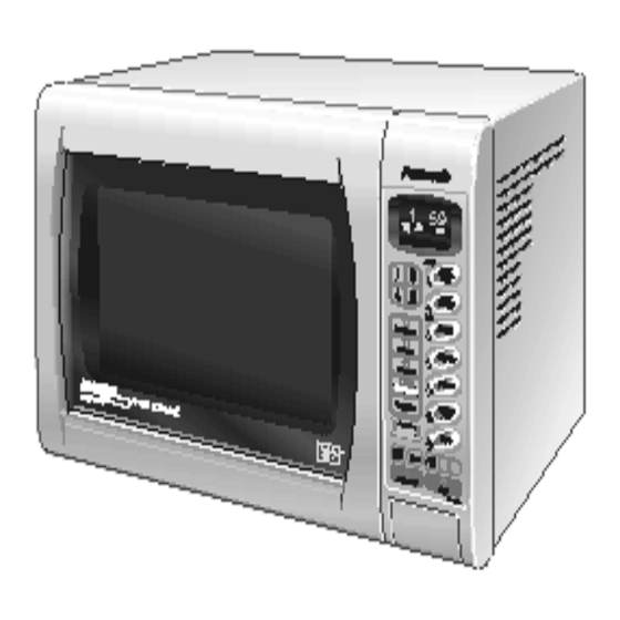
Order Number MOP00080014C2
Microwave Oven
510mm(W) x 477mm(D) x 314mm(H)
359mm(W) x 352mm(D) x 217mm(H)
© 1995 Matsushita Electric Industrial Co., Ltd. All
rights reserved. Unauthorized copying and distribu-
tion is a violation of law.
99 Minutes 99 Seconds
27L
15Kg
Advertisement
Table of Contents

Related Manuals for Panasonic NN-A750WB


Summary of Contents for Panasonic NN-A750WB
-
Page 1: Microwave Oven
Order Number MOP00080014C2 Microwave Oven NN-A750WB NN-A720MB NN-A770SB WHITE SILVER STAINLESS United Kingdom Specification 99 Minutes 99 Seconds Timer Power Source 240VAC Single phase, 50Hz Oven Cavity Size Outside Dimensions 510mm(W) x 477mm(D) x 314mm(H) Power Requirements Micro 1260W Grill 1360W Conv 1470w Combi... -
Page 2: Inverter Warning
1 Inverter Warning The inverter board looks like a regular PCB, however, this PCB drives the magnetron tube using very high voltages and cur- rent. It has 1. Very high voltage and high current 2. An Aluminium heat sink that becomes very hot 3. -
Page 3: Control Panels
3 Control Panels... -
Page 4: Operation And Digital Programmer Circuit Test Procedure
4 Operation And Digital Programmer Circuit Test Procedure 4.1. Setting The Clock 4.4. Delay Stand (1) Plug the power supply (1) Set power level and time cord into the wall outlet (2) Press Stand (2) Press the clock pad (3) Set standing time (3) Enter the time of the day (4) Press Start (4) Press the clock pad... - Page 5 4.8. Turbo Bake Operation 4.10. Combination Cooking (Grill And Microwave) (1) Press turbo bake pad to select oven temperature (1) Press combination pad (2) Press grill pad to select (2) Press grill pad to select grill power oven temperature (3) Press start to preheat (3) Select micro power (4) Press time pads to enter cooking time...
-
Page 6: Auto Weight Cook Programs
4.12. Auto Weight Cook Programs (1) Select the desired auto weight cook program (2) Press to select grams or pounds and ounces (3) Enter weight pressing the up and down pads (4) Press Start... - Page 7 5 Schematic Diagram 6 Wiring Diagram...
-
Page 8: Variable Power Cooking Control
7 Description of Operating instruction 7.1. Variable power cooking control 7.3. Auto weight defrost, Auto weight Cook The HIGH VOLTAGE INVERTER POWER SUPPLY controls the output power by a signal from the digital Programmer circuit When an auto control feature is selected and the start pad DPC. -
Page 9: Convection Cooking
7.4. Convection Cooking 1. The digital programmer circuit operates the power relays temperature, the digital programmer circuit supplies RY3,RY5 and RY6 in the sequence as shown in the fig- power to power relay RY5 resulting in the convection ure below. heater turning on. -
Page 10: Combination Cooking
7.5. Combination Cooking With convection, grill and micro power combination. The grill Combination cooking is achieved by operating the microwave elements and convection elements are operated alternatively and heater modes together during one cooking cycle. There whilst the oven temperature is above the selected level. are three combination modes. - Page 11 Grill and Microwave Duty Cycles Figure 2 Grill, Convection And Microwave Duty Cycles...
- Page 12 Figure 3...
-
Page 13: Cautions To Be Observed When Troubleshooting
8 Cautions to Be Observed When Troubleshooting Unlike many other appliances, the microwave oven is a high voltage, high current is device. Though it is free from danger in ordinary use, extreme care should be taken during repair. Caution Servicemen should remove their watches whenever work- ing close to or replacing the magnetron. -
Page 14: Confirm After Repair
8.3. When parts must be replaced, 8.6. Confirm after repair 1. After repair or replacement of parts, make sure that the remove the power plug from screws of the oven, etc. are neither loose nor missing. the outlet. Microwaves might leak if screws are not properly tight- ened. -
Page 15: Parts Replacement Procedure
9 Parts Replacement Procedure 9.1. Magnetron Caution when replacing the inverter power supply (U) 1. Make sure that grounding plate is in place 1. Discharge the high voltage capacitors on the inverter cir- 2. Securely tighten the grounding screw through the side of cuit. -
Page 16: Low Voltage Transformer And/ Or Power Relays (Ry1)
1. Remove the escutcheon bracket from the escutcheon 9.4. Low voltage transformer and/ base by freeing the 4 catch hooks on the escutcheon or power relays (RY1) base. 2. Peel away the display window from the inside of the base. Note Be sure to ground your body to discharge any static 3. -
Page 17: Quartz Heater
screen from the door A catch hooks. Care must be taken 2. Disconnect the two lead wires connected to the turntable not to damage these hooks during disassembly. motor 4. Remove the door key and spring form the door E 3. - Page 18 One screw to remove the grill bracket Figure 11 Removing the grill element Figure 12...
-
Page 19: Temperature Sensor
5. Remove the two screws C holding the convection assem- 9.9. Convection Element And Cir- bly, push upwards to remove. culation Fan Motor 6. To remove the convection element remove the one screw 1. Remove the four screws A holding the rear heater cover. E on the convection bracket A and 2 screws D on convec- 2. -
Page 20: Component Test Procedure
10 Component Test Procedure Caution 1. High voltage is present at the high voltage terminal of the inverter unit, including the aluminium heat sink. 2. It is not necessary or advisable to attempt to measure this high voltage. 3. Before touching any oven components, or wiring, always unplug the oven from its power source and discharge the high voltage capacitors. -
Page 21: Inverter Power Supply
10.5. Inverter Power Supply Caution DO NOT try to repair this inverter power supply). Replace as a whole H.V. Inverter Unit. Figure 3 Inverter Power Supply Diagram 10.6. Inverter Power Supply Unit Warning Do not attempt to make any measurements in the high volt- age circuitry of the inverter or magnetron. -
Page 22: Measurements And Adjustments
11 Measurements and Adjustments Warning • For continued protection against radiation hazard, replace only with identical parts. • When the 10 amp fuse is blown due to the operation of the short switch, you must replace the primary latch switch and short switch. -
Page 23: Troubleshooting Guide
12 Troubleshooting guide Caution 1. Do not try to repair this H.V. Inverter power supply. Replace as a whole unit. When returning the inverter unit pack in the orig- inal inverter box. 2. Do not adjust the preset volume on the H.V. Inverter. It is very dangerous to repair or adjust without sufficient test equiptment, this circuit handles very high volatge and current 3. - Page 24 Troubleshooting (Fuse is blown) Figure 2 Troubleshooting (Other problems) Figure 3...
- Page 25 Troubleshooting Inverter by Input out voltage Figure 4 Troubleshooting Inverter by Microwave Oven Input Current Figure 5...
- Page 26 13 Digital Programmer Circuit Troubleshooting Guide How to test the semiconductors...