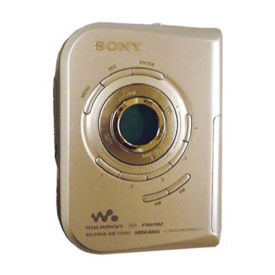
Sony WM-FX495 Service Manual
Radio cassette player
Hide thumbs
Also See for WM-FX495:
- Operating instructions (3 pages) ,
- Manual de instrucciones (2 pages) ,
- Specifications (2 pages)
Table of Contents
Advertisement
SERVICE MANUAL
Ver. 1.2 2005.12
• Frequency range
FM : 87.5 - 108 MHz
AM: 530 - 1 710 kHz (North, America)
531 - 1 602 kHz (Other countries)
• Output
Headphones (i) jack Load impedance 8 - 300 Ω
• Power requirements
1.5V DC, battery R6 (size AA) x 1
• Dimensions (w/h/d)
Approx. 81.1 x 111.2 x 29.3 mm (3
projecting parts and controls
• Mass
Approx. 137 g (4.9 oz) (main unit only)
• Supplied accessories
Stereo headphones or earphones with remote control (1)
Carrying case or Carrying pouch or Hand strap (1)
Design and specifications are subject to change without notice.
Sony Corporation
9-877-098-03
2005L02-1
Personal Audio Division
© 2005.12
Published by Sony Engineering Corporation
Model Name Using Similar Mechanism
MD Mechanism Type
SPECIFICATIONS
1
1
3
⁄
x 4
⁄
x1
⁄
in.), excl.
4
2
16
WM-FX495
Battery life* (approximate hours)
Sony alkaline
LR6 (SG)**
Tape playback
35
Radio reception
40
* Measured value by the standard of JEITA (Japan Electronics and
Information Technology Industries Association).
(Using a Sony HF series cassette tape)
**When using a Sony LR6(SG) "STAMINA" alkaline dry
battery (produced in Japan).
Note
• The battery life may be shorter depending on the operating condition, the
surrounding temperature and battery type.
RADIO CASSETTE PLAYER
US Model
AEP Model
NEW
MF-WMFX495-147
Sony R6P
(SR)
9
14
Advertisement
Table of Contents

Related Manuals for Sony WM-FX495


Summary of Contents for Sony WM-FX495
-
Page 1: Specifications
• Mass (Using a Sony HF series cassette tape) Approx. 137 g (4.9 oz) (main unit only) **When using a Sony LR6(SG) “STAMINA” alkaline dry • Supplied accessories battery (produced in Japan). Stereo headphones or earphones with remote control (1) -
Page 2: Table Of Contents
WM-FX495 TABLE OF CONTENTS Flexible Circuit Board Repairing Specifications ................1 • Keep the temperature of the soldering iron around 270°C during 1. SERVICING NOTE repairing............3 • Do not touch the soldering iron on the same conductor of the circuit board (within 3 times). -
Page 3: Servicing Note
WM-FX495 SECTION 1 SERVICING NOTES This set detects the rotation of the idler gear (A) (side S) using the 3. FF, REW modes photo reflector (PH751). The PH751 is mounted on the MAIN 1) Check that the preset state is set. -
Page 4: General
WM-FX495 SECTION 2 GENERAL This section is extracted from instruction manual. LOCATING THE CONTROLS –Tape mode– Plug in firmly. Y •DIRECTION** VOL* MENU OPEN x•RADIO OFF FF•PRESET/ REW•PRESET/ TUNING+ TUNING – HOLD * There is a tactile dot beside VOL on the main unit to show the direction to turn up the volume. -
Page 5: Disassembly
WM-FX495 SECTION 3 DISASSEMBLY The equipment can be removed using the following procedure. Cabinet (front) sub ASSY MAIN board Mechanism deck Cassette holder sub ASSY Note : Follow the disassembly procedure in the numerical order given. 3-1. CABINET (FRONT) SUB ASSY 2 Screw (B 1.7 ×... -
Page 6: Main Board
WM-FX495 3-2. MAIN BOARD 3 Unsolder L4 leads (three places) 4 Screw (1.7 × 2.5), tapping 2 Unsolder leads from motor (four places) 7 MAIN board Cabinet (center) ASSY 1 Unsolder HEAD flexible board 5 Claws 3-3. MECHANISM DECK 3 Mechanism deck... -
Page 7: Cassette Holder Sub Assy
WM-FX495 3-4. CASSETTE HOLDER SUB ASSY 3 Spring (lid up) 4 Cassette holder sub ASSY • Use caution when installing the cassette holder assy Install the cassette holder sub ASSY with the spring (lid up) as shown below in the drawing so that it fits into the holes on the cabinet center. -
Page 8: Adjustments
WM-FX495 SECTION 4 ADJUSTMENTS 4-1. MECHANICAL ADJUSTMENTS Tape Speed Adjustment Procedure : PRECAUTION test tape WS-48A frequency counter 1. Clean the following parts with a denatured-alcohol-moistened (3kHz, 0dB) swab : 16 Ω playback head pinch roller capstan rubber belt 2. Demagnetize the playback head with a head demagnetizer. - Page 9 WM-FX495 • Repeat the procedures in each adjustment several times, and the TUNER SECTION 0 dB = 1µV frequency coverage and tracking adjustments should be finally AM section done by the trimmer capacitors. no mark : US BAND : AM <...
- Page 10 WM-FX495 Adjustment Location : [MAIN BOARD] (SIDE B) [MAIN BOARD] (SIDE A) L5 : AM Frequency Coverage Adjustment L4 : AM Tracking Adjustment CT1 : AM Tracking Adjustment L7 : FM Tracking Adjustment...
-
Page 11: Diagrams
WM-FX495 SECTION 5 DIAGRAMS 5-1. BLOCK DIAGRAMS FM/AM FRONT END (FM DISC) IF DET, FM MPX QUAD IC701 (1/2) LOUT (FM IF) RF IN IF IN SYSTEM LCD1 CONTROL ROUT R-CH LIQUID FMRFOUT COM1 CRYSTAL DISPLAY TRACKING LPF1 COM4 MONO/STEREO... -
Page 12: Printed Wiring Boards
WM-FX495 5-2. PRINTED WIRING BOARDS See page 15 for Notes. (SIDE B) MAIN BOARD MAIN BOARD (SIDE A) N VOL FERRITE-BAR ANTENNA DIRECTION Semiconductor Location Ref. No. Location DRY BATTERY SIZE "AA" (IEC DESIGNATION LR6) 1PC, 1.5V HP601 PLAYBACK D401... -
Page 13: Schematic Diagram -Main Section (1/2)
WM-FX495 5-3. SCHEMATIC DIAGRAM –MAIN SECTION (1/2) – See page 15 for Notes. -
Page 14: Schematic Diagram -Main Section (2/2)
WM-FX495 5-4. SCHEMATIC DIAGRAM –MAIN SECTION (2/2) – See page 15 for Notes. -
Page 15: Ic Block Diagrams
WM-FX495 Note on Schematic Diagram • All capacitors are in µF unless otherwise noted. pF: µµF 50 Waveforms WV or less are not indicated except for electrolytics and tantalums. • All resistors are in Ω and W or less unless otherwise speci- fied. - Page 16 WM-FX495 IC301 TA2160FN (EL) RF & REF PW C AGC DET PW A PW B PRE A PRE B BST SW IC601 MM1279XVBE MOTIVE CONTROL DRIVER CIRCUIT MOTIVE SOFT MOTIVE LOGIC SWITCH /OSC INVERTER BIAS VREF SPEED CURRENT REFERENCE CONTROL...
-
Page 17: Exploded Views
WM-FX495 SECTION 6 Ver. 1.2 EXPLODED VIEWS NOTE : • -XX, -X mean standardized parts, so they • Items marked “ * ”are not stocked since they are seldom • Hardware (# mark) list and accessories and may have some difference from the original required for routine service. -
Page 18: Mechanism Deck Section
WM-FX495 6-2. MECHANISM DECK SECTION (MF-WMFX495-147) not supplied not supplied HP601 M601 Ref. No. Part No. Description Remark Ref. No. Part No. Description Remark X-3375-020-2 PINCH LEVER (N-F) ASSY 3-238-876-04 SCREW (M1.4), TOOTHED LOCK X-3372-619-1 WHEEL ASSY (NP), CAPSTAN X-3375-021-3 PINCH LEVER (R-F) ASSY 3-354-868-01 BELT 3-704-197-71 SCREW (M1.4x4.5) -
Page 19: Electrical Parts List
WM-FX495 SECTION 7 MAIN ELECTRICAL PARTS LIST NOTE : • Due to standardization, replacements in the • Items marked “ * ”are not stocked since they When indicating parts by reference num- parts list may be different from the parts are seldom required for routine service. - Page 20 WM-FX495 MAIN Ref. No. Part No. Description Remark Ref. No. Part No. Description Remark C410 1-107-819-11 CERAMIC CHIP 0.022uF IC601 8-759-356-46 IC MM1279XVBE C411 1-164-937-11 CERAMIC CHIP 0.001uF IC701 6-802-987-01 IC TC9328AF-117 C412 1-165-128-11 CERAMIC CHIP 0.22uF C414 1-164-935-11 CERAMIC CHIP...
- Page 21 WM-FX495 MAIN Ref. No. Part No. Description Remark Ref. No. Part No. Description Remark 1-216-845-11 METAL CHIP 100K 1/10W R330 1-216-821-11 METAL CHIP 1/10W R331 1-216-821-11 METAL CHIP 1/10W 1-216-833-11 METAL CHIP 1/10W R333 1-218-941-81 RES-CHIP 1/16W 1-216-853-11 METAL CHIP...
- Page 22 WM-FX495 MAIN Ref. No. Part No. Description Remark Ref. No. Part No. Description Remark R733 1-218-981-11 RES-CHIP 220K 1/16W (SPANISH, PORTUGUESE, DUTCH)(AEP) R734 1-218-981-11 RES-CHIP 220K 1/16W 3-253-259-41 MANUAL, INSTRUCTION R735 1-216-849-11 METAL CHIP 220K 1/10W (SWEDISH, FINNISH, RUSSIAN)(AEP) R751...
- Page 23 WM-FX495 MEMO...
- Page 24 WM-FX495 REVISION HISTORY Clicking the version allows you to jump to the revised page. Also, clicking the version at the upper right on the revised page allows you to jump to the next revised page. Ver. Date Description of Revision 2003.02...