Sony Walkman WM-FX491 Service Manual
Sony radio cassette player service manual
Hide thumbs
Also See for Walkman WM-FX491:
- Operating instructions (2 pages) ,
- Operating instructions (2 pages) ,
- Operating instructions (2 pages)
Table of Contents
Advertisement
WM-FX491/FX491ST/FX493/FX493ST
SERVICE MANUAL
Ver 1.0 2000.01
MICROFILM
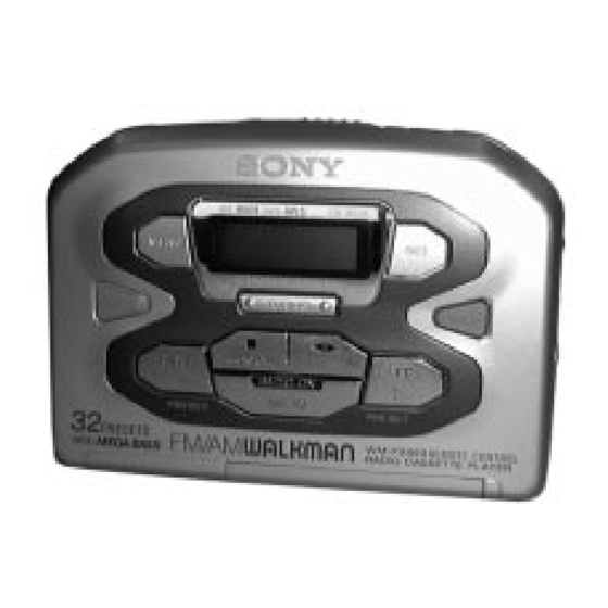
Photo : WM-FX493
SPECIFICATIONS
• Frequency range
FM: 87.5–108 MHz
AM: 530–1710 kHz (US, Canadian, 5E, 6E model)
531–1602 kHz (EXCEPT US, Canadian, 5E, 6E model)
• Power requirements
3 V DC batteries R6 (size AA) x 2
• Dimensions (w/h/d)
Approx. 115.8 x 83.2 x 30.1 mm, incl. projecting parts and
controls
• Mass
Approx. 115 g/Approx. 195 g (incl. a battery and a cassette)
• Supplied accessories
Stereo headphones or earphones with remote control (1)
(FX493/FX493ST)/Stereo headphones or earphones (1)
(FX491/FX491ST)
Design and specifications are subject to change without
notice.
• Abbreviation
5E, 6E : South America
Battery life (approximate hours)
Sony alkaline LR6 (SG) Sony R6P (SR)
Tape playback
25
Radio reception
40
* Measured value by the standard of EIAJ (Electronic
Industries Association of Japan). (Using a Sony HF series
cassette tape)
Note
• The battery life may shorten depending on the operation of
the unit.
Canadian Model
WM-FX491/FX491ST/FX493ST
Chinese Model
Model Name Using Similar Mechanism
Tape Transport Mechanism Type
(EIAJ*)
7.5
14
RADIO CASSETTE PLAYER
US Model
WM-FX493/FX493ST
AEP Model
E Model
WM-FX491/FX493
WM-FX477
MT-WMEX404-147
Advertisement
Table of Contents

Related Manuals for Sony Walkman WM-FX491


Summary of Contents for Sony Walkman WM-FX491
- Page 1 Sony alkaline LR6 (SG) Sony R6P (SR) Tape playback Radio reception * Measured value by the standard of EIAJ (Electronic Industries Association of Japan). (Using a Sony HF series cassette tape) Note • The battery life may shorten depending on the operation of the unit.
-
Page 2: Table Of Contents
TABLE OF CONTENTS Specifications ................1 1. GENERAL Location and Function of Controls ........3 2. DISASSEMBLY 2-1. Cabinet (Front) Sub ASSY ......... 5 2-2. Main Board ..............5 2-3. Mechanism Deck ............6 2-4. Belt, Motor (Capstan/Reel) (M901) ......6 2-5. -
Page 3: General
SECTION 1 This section is extracted from GENERAL instruction manual. LOCATION AND FUNCTION OF CONTROLS FX493 Y•x (RADIO ON/BAND•OFF) OPEN HOLD FF/PRESET + MB MODE TAPE AVLS FM MODE REW/PRESET – FX493 MENU ENTER Plug in firmly. HOLDB Branchez fermement. FX491 TUNING+/–... - Page 4 Listening to the Radio Preparations To emphasize bass sound Press MENU repeatedly to set the cursor to MB in the To Insert Batteries 1 If the HOLD function is turned on, slide the display. Then, press SET to turn MB on. With each HOLD switch in the opposite direction of press, the indications change as follows.
-
Page 5: Disassembly
SECTION 2 DISASSEMBLY The equipment can be removed using the following procedure. Cabinet (Front) sub ASSY Main board Mechanism deck Belt, Motor (Capstan/reel) (M901) Holder sub ASSY, Cassette Note : Follow the disassembly procedure in the numerical order given. 2-1. CABINET (FRONT) SUB ASSY 4 Screws (B1.7x12) 5 Claws Center cabinet... -
Page 6: Mechanism Deck
2-3. MECHANISM DECK Mechanism deck Center cabinet 1 Claws 2-4. BELT, MOTOR (CAPSTAN/REEL) (M901) 2 Screws (M1.4) 3 Motor (Capstan/reel) (M901) • How to apply the belt belt M901 wheel assy (SP), capstan 1 belt – 6 –... -
Page 7: Holder Sub Assy, Cassette
2-5. “HOLDER SUB ASSY, CASSETTE” 3 Move hinge away from projection Hinge Projection 3 Move hinge away Center cabinet from projection Hinge Projection 1 OPEN Hinge Hinge 5 Spring (lid up) Holder sub ASSY, Cassette CAUTIONS DURING ASSEMBLY 1 Insert the spring (Lid up) to the slot as shown in the figure. 2 3 Insert the hinge of the “Holder sub ASSY, Cassette”. -
Page 8: Adjustments
SECTION 3 ADJUSTMENTS 3-1. MECHANICAL ADJUSTMENTS 3-2. ELECTRICAL ADJUSTMENTS PRECAUTION PRECAUTION 1. Clean the following parts with a denatured-alcohol-moistened • Supplied voltage : 2.5V. swab : • Switch and control position playback head pinch roller MEGA BASS : OFF capstan rubber belt VOLUME control : maximum 2. - Page 9 • Repeat the procedures in each adjustment several times, and the TUNER SECTION 0 dB = 1µV frequency coverage and tracking adjustments should be finally AM Section done by the trimmer capacitors. BAND : AM < > : US, Canadian, 5E, 6E model ] : Saudi Arabia model AM RF signal Put the lead-wire...
- Page 10 Frequency Coverage Adjustment Setting : digital voltmeter (DC range) TP781 (VT) [MAIN BOARD] TP809 (GND) (Side B) Adjustment Location : L4 : AM Frequency Coverage Adjustment L1 : FM Tracking Adjustment [MAIN BOARD] (SIDE A) T1 : AM IF Adjustment L2 : AM Tracking Adjustment CT1 : AM Tracking Adjustment L3 : FM Frequency Coverage Adjustment...
-
Page 11: Diagrams
WM-FX491/FX491ST/FX493/FX493ST SECTION 4 DIAGRAMS 4-2. BLOCK DIAGRAM 4-1. EXPLANATION OF IC TERMINALS Pin No. Pin Name Pin Description IC701 TC9327AF-621 (SYSTEM CONTROL/LCD DRIVE) VCO AM VCO (AM) input. Pin No. Pin Name Pin Description — Power supply pin. RESET Reset input. Connect to VDD. - Page 12 WM-FX491/FX491ST/FX493/FX493ST 4-3. PRINTED WIRING BOARDS Semiconductor Location Ref. No. Location DRY BATTERY C-18 SIZE "AA" (DESIGNATION R6) [MAIN BOARD] 2PCS, 3V D301 B-19 (SIDE B) [MAIN BOARD] (SIDE A) D401 E-14 D402 E-14 J301 IC101 IC701 C-14 IC702 B-17 IC703...
-
Page 13: Schematic Diagram
WM-FX491/FX491ST/FX493/FX493ST 4-4. SCHEMATIC DIAGRAM Refer to page 22 for IC Block Diagram. Waveforms 290 mVp-p 75 kHz IC701 uf VOLT/DIV : 50 mV AC TIME/DIV : 5 µsec XOUT 3.2 Vp-p 369 nsec VOLT/DIV : 1 V AC Q401 C TIME/DIV : 0.1 msec... -
Page 14: Exploded Views
SECTION 5 EXPLODED VIEWS NOTE : IC Block Diagram. 5-2. MECHANISM DECK SECTION • Abbreviation • -XX, -X mean standardized parts, so they • The mechanical parts with no reference (MT-WMEX404-147) IC1 TA2104AFN (EL) may have some difference from the original number in the exploded views are not CND : Canadian : French... -
Page 15: Electrical Parts List
SECTION 6 MAIN ELECTRICAL PARTS LIST NOTE : • Due to standardization, replacements in the • SEMICONDUCTORS When indicating parts by reference num- In each case, u : µ , for example : parts list may be different from the parts ber, please include the board. - Page 16 MAIN Ref. No. Part No. Description Remark Ref. No. Part No. Description Remark C714 1-115-156-11 CERAMIC CHIP < JUMPER RESISTOR > C715 1-164-156-11 CERAMIC CHIP 0.1uF C716 1-164-156-11 CERAMIC CHIP 0.1uF JC101 1-216-296-00 METAL CHIP 1/8W C717 1-164-156-11 CERAMIC CHIP 0.1uF JC102 1-216-296-00 METAL CHIP...
- Page 17 MAIN Ref. No. Part No. Description Remark Ref. No. Part No. Description Remark 1-216-296-91 SHORT R702 1-216-841-11 METAL CHIP 1/16W 1-216-833-91 RES-CHIP 1/16W R703 1-216-805-11 METAL CHIP 1/16W 1-216-821-11 METAL CHIP 1/16W R704 1-216-835-11 METAL CHIP 1/16W 1-216-845-11 METAL CHIP 100K 1/16W (EXCEPT US,CND,5E,6E)
- Page 18 WM-FX491/FX491ST/FX493/FX493ST Ref. No. Part No. Description Remark ACCESSORIES & PACKING MATERIALS ******************************** 1-505-521-11 HEADPHONE (MDR-023) (FX491:CND) 1-505-521-21 HEADPHONE (MDR-023SP) (FX493:US) 3-042-385-01 CASE, CARRYING (FX491:CND,5E,6E,FX491ST/ FX493:US,5E,6E,FX493ST) 3-044-230-01 CLIP, BELT (FX491:CND,5E,6E,FX491ST/ FX493:US,5E,6E,FX493ST) 3-318-203-71 SCREW (B1.7X5), TAPPING (FX493,FX493ST) 3-867-999-11 MANUAL, INSTRUCTION (FX491:AEP,FR/FX493:AEP,FR) (ENGLISH,FRENCH,GERMAN,ITALIAN)