Table of Contents
Advertisement
SPLIT TYPE
AIR CONDITIONER
DUCT TYPE (50Hz)
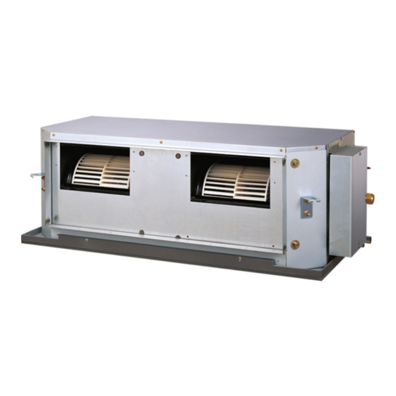
Indoor unit
ARYC45LCTU
ARYC54LCTU
CONTENTS
SPECIFICATIONS . . . . . . . . . . . . . . . . . .
DIMENSIONS. . . . . . . . . . . . . . . . . . . . . .
CIRCUIT DIAGRAM . . . . . . . . . . . . . . . . .
INDOOR PCB CIRCUIT DIAGRAM . . . . .
ERROR DETECTION. . . . . . . . . . . . . . .
PARTS (INDOOR UNIT) . . . . . . . . . . . .
PARTS (OUTDOOR UNIT) . . . . . . . . . .
ACCESSORIES . . . . . . . . . . . . . . . . . . .
Outdoor unit
AOYA45LCTL
AOYA54LCTL
1
2
4
5
6
7
. . .
12
16
18
21
Advertisement
Table of Contents

Related Manuals for Fujitsu ARYC45LCTU


Summary of Contents for Fujitsu ARYC45LCTU
-
Page 1: Table Of Contents
SPLIT TYPE AIR CONDITIONER DUCT TYPE (50Hz) Indoor unit Outdoor unit ARYC45LCTU AOYA45LCTL ARYC54LCTU AOYA54LCTL CONTENTS SPECIFICATIONS ....DIMENSIONS..... . -
Page 2: Specifications
SPECIFICATIONS ELECTRICAL DATA NOISE LEVEL High Cooling & Heating 47 dB TYPE INDOOR UNIT Medium 43 dB ARYC45LCTU ARYC54LCTU INDOOR UNIT OUTDOOR UNIT AOYA45LCTL AOYA54LCTL 40 dB COOLING CAPACITY 12.5 kW 13.4 kW Cooling 55 dB 55 dB OUTDOOR UNIT... -
Page 3: Dimensions
DIMENSIONS INDOOR UNIT (Unit : mm) 1,080 1,000 1,050 2008.11.21... - Page 4 OUTDOOR UNIT (unit : mm) air flow 2011.02.23...
-
Page 5: Refrigerant System Diagram
REFRIGERANT SYSTEM DIAGRAM OUTDOOR UNIT INDOOR UNIT Refrigerant Pipe Pressure 15.88mm (5/8") Check Valve 3-way Valve Muffler Pressure Sensor 4-way Valve Heat Heat Check Exchanger Exchanger Valve High Pressure Accumulator Switch Muffler Compressor Refrigerant Pipe 9.52mm (3/8") Strainer Strainer Expansion 3-way Valve Valve Thermistor (Room) -
Page 6: Circuit Diagram
HIGH PRESSURE SWITCH CN101 WHITE OUTDOOR UNIT BLACK THERMISTOR WHITE CN61 CIRCUIT DIAGRAM ( OUTDOOR TEMP. ) WHITE BLACK WHITE BLACK THERMISTOR WHITE BLACK ( PIPE TEMP. ) WHITE CN63 WHITE MAIN PCB CN401 BLACK CN40 THERMISTOR ( PIPE - MID. TEMP. ) WHITE BLACK WHITE... -
Page 7: Indoor Pcb Circuit Diagram
INDOOR PCB CIRCUIT DIAGRAM MAIN PCB ARYC45LCTU : K03BZ-0802HSE-C1 ARYC54LCTU : K03BZ-0801HSE-C1 CN104 B02B-XARK-1-A CN105 R15 - R17 B04B-PASK-1 TRANS (SEC) 10K <1/10W> x 3 DC SUPPLY WHITE JM103 UL1430 AWG22 UL1430 AWG26 GRAY R18 - R20 UL1430 AWG22 DSS803... -
Page 8: Outdoor Pcb Circuit Diagram
OUTDOOR PCB CIRCUIT DIAGRAM INVERTER ASSEMBLY AOYA45LCTL : EZ-0101SHUE AOYA54LCTL : EZ-0101THUE EMI FILTER RFC-10 F103 F104 EMI FILTER W100 UL1015 AC250V 30A AC250V 3.15A POWER SOURCE ZCAT2132-1130 AWG12 AC230V BLACK W102 50Hz UL1015 TM101 AWG12 UL1015 W101 ORANGE AWG12 WHITE POWER SUPPLY PCB UL1015... - Page 9 OUTDOOR UNIT MAIN PCB - 1 AOYA45LCTL : K10BS-1005HUE-C1 AOYA54LCTL : K10BS-1006HUE-C1 C167, C168 R163 340V 330p <CH> <1/10W> 12V-2 D200 L152 D3F60 BLm31PG121 C152 D153 220/ 3-1747052-4 RF101L2S YELLOW C214 D203 D231 AC I N R219, R220 L155 2200p 1SS355 RF301B2S 1.8k <1/4W>...
- Page 10 OUTDOOR UNIT MAIN PCB - 2 AOYA45LCTL : K10BS-1005HUE-C1 AOYA54LCTL : K10BS-1006HUE-C1 CN12 B02B-XAKK-1-A C802 L800 15V-2 BLACK 15V-2 340V Q801 P_EX_OUT1 BL02Rn1 CN800 <B> EX. OUT 1 DTA143EUA B6P-VH-B I C10-7 WHITE D801 uLN2003 R800 RD24FM FTR-F3 <1/10W> BLm18AG601 DC FAN MOTOR 1 C800 P_FM1_PWM...
- Page 11 OUTDOOR UNIT TRANSISTOR PCB ( I P M ) K10AY-1003HUE-TR0 C209 - C211, C221 C222 C302 0.1 <F> 100/ L300 <F> BL02Rn1 TM303 C332 TM101 86028 D307 86028 C161 RD24FM <F> <X7R> I PM-G TM102 TM304 86028 BLACK 86028 D100 LL25XB60 I C301 TM305...
- Page 12 OUTDOOR UNIT CAPACITOR PCB K05FB-1000HUE-P0 WHITE YELLOW C200 - C203 R200 660/ 220k 450V <2W> BLUE VIOLET POWER_G OUTDOOR UNIT INDICATOR PCB K10BC-1000YUE-D0 D401 SLR-325 <ORANGE> D402 SLR-325 <ORANGE> D403 SLR-325 <ORANGE> ( CN401-1 ) D404 SLR-325 <ORANGE> ( CN401-2 ) D405 SLR-325 ( CN401-3 ) <ORANGE>...
-
Page 13: Error Detection
ER R OR D ETEC TION REMOTE CONTROL Error Troubleshooting at the remote control LCD Error contents code This is possible only on the wired remote control. Indoor signal error Self-diagnosis If an error occurs, the following display will be shown. Wired remote control abnormal (“EE”... - Page 14 ERROR DETECTION OUTDOOR UNIT Indicator PCB Display when an error occurs. PUMP PEAK POWER ERROR DOWN NOISE LEDs MODE (L1) (L2) (L3) (L4) (L5) (L6) Blink (Hi speed) Buttons Check that the “ERROR” LED blinks, then press the [Enter] button once. The "POWER MODE"...
-
Page 15: Test Run
OUTDOOR UNIT TEST RUN Before the test run, refer to he figure and check the following items. Setting method Is the outdoor unit securely installed? Turn on the power of the outdoor unit and enter standby mode. Have you performed gas leakage inspection? PUMP PEAK (Connection joints of various pipes (flang connection, brazing)) -
Page 16: Pump Down
OUTDOOR UNIT PUMP DOWN Procedure WARNING (1) Check the 3-way valves (both the liquid side and gas side) are opened. Never touch electrical components such as the terminal blocks except the button on (2) Turn the power on. the display board. It may cause a serious accident such as electric shock. PUMP PEAK During the pump-down operation, make sure that the compressor is turned off before... -
Page 17: Parts (Indoor Unit)
PARTS INDOOR UNIT Ref. Description Parts number Top Plate Sub Assy 9372576014 Kit (Front Panel Sub Assy) 9372637029 Fan Panel Assy 9372035009 Motor Bracket Assy 9372037003 Motor Bracket B 9372039007 Fan Motor 9602802012 Casing A 9372057018 Casing B 9372058015 (Connector : black) (Connector : white) Sirocco Fan 9372059029... - Page 18 INDOOR UNIT Ref. Description Parts number Control Box Assy 9374854028 Power Supply PCB Assy 9705668102 Controller PCB Assy (45) 9705246232 Controller PCB Assy (54) 9705246225 Transformer (Power) 9704129017 Terminal 3P 9703345012 Terminal 3P 9306489045 Relay 9900294014 Capacitor, Plastic 9900269111 Capacitor Clamp 9308114006 Remote Control 9372266199...
-
Page 19: Parts (Outdoor Unit)
PARTS OUTDOOR UNIT Ref. Description Parts number Ref. Description Parts number Top Panel Sub Assy 9374417056 Motor, DC Brushless 9602843039 Front Panel Sub Assy 9374414109 Propeller Fan Assy 9366378020 Sevice Panel Sub Assy 9374415090 RFM Top Assy 9380420002 Rear Emblem 9351355005 Condenser A Sub Assy 9374420261... - Page 20 Ref. Description Parts number Terminal Cover 9380328001 Inverter Cover 9380329008 Inverter Case Main Assy 9380340003 Inverter Case Assy 9380342007 Case Bottom 9380325000 Inverter RFM A 9380375005 Inverter RFM B 9380401001 Inverter PCB Assy (45) 9708690063 Inverter PCB Assy (54) 9708690070 Indicator PCB Assy 9708678016 Terminal...
- Page 21 OUTDOOR UNIT Ref. Description Parts number Separate Wall Sub Assy 9374413218 Valve Plate 9378804012 Ref. Description Parts number 3-way Valve Assy 9379079006 Solenoid 9970055072 3-way Valve Assy 9379077002 4-way Valve Assy 9374425235 Compressor Plate Assy 9380344001 Discharge Pipe Assy 9371581248 Compressor 9810153005 Pressure Switch...
-
Page 22: Accessories
A C C ESSOR IES INDOOR UNIT Name and Shape Q'ty Application Part number Special nut A 313005446653 (large flange) For suspending the indoor unit from ceiling Special nut B 313005446759 (small flange) Coupler heat insulation (large) For indoor side pipe joint 9378173569 (large pipe) Coupler heat... - Page 23 1202G4027...