Table of Contents
Advertisement
Advertisement
Table of Contents

Related Manuals for ABB ACS-AP-x


Summary of Contents for ABB ACS-AP-x
- Page 1 Options for ABB drives User’s manual ACS-AP-x Assistant control panels...
-
Page 2: List Of Related Manuals In English
You can find manuals and other product documents in PDF format on the Internet. See section Document library on the Internet on the inside of the back cover. For manuals not available in the Document library, contact your local ABB representative. - Page 3 User’s manual ACS-AP-x Assistant control panels Table of contents 2015 ABB Oy. All Rights Reserved. 3AUA0000085685 Rev D EFFECTIVE: 2015-10-15...
-
Page 5: Table Of Contents
Table of contents 5 Table of contents List of related manuals in English ..........2 1. - Page 6 6 Table of contents 5. Functions in the main Menu What this chapter contains ........... 29 Menu .
- Page 7 Providing feedback on ABB Drives manuals ........
- Page 8 8 Table of contents Document library on the Internet ..........65...
-
Page 9: Introduction To The Manual
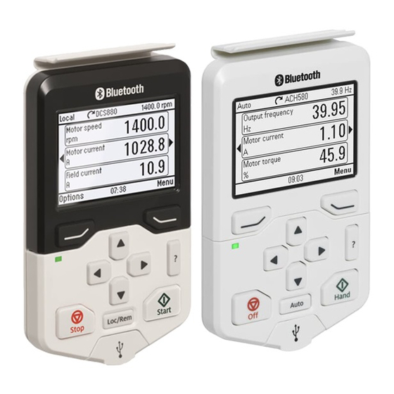
This manual is applicable with ACS-AP-I, ACS-AP-S control panels with hardware revision C and software version 4.61 or later and with ACS-AP-W control panel with hardware revision A. The control panel types are referred as ACS-AP-x in this manual. The images and instructions are based on the use of the control panel with an ACS880 and ACS580 drives. - Page 10 10 Introduction to the manual • Installation and start-up describes the installation and start-up of the control panel. • Control panel overview describes the main parts of the control panel and their functions. • Basic operation describes the menu structure, views and basic functions of the control panel.
-
Page 11: Installation And Start-Up
Installation and start-up 11 Installation and start-up What this chapter contains The chapter describes how to install and start-up the Assistant control panel for the first time. Installation Attach the control panel directly to the drive or use a separate mounting kit (for example, for cabinet door mounting). -
Page 12: First Start-Up
12 Installation and start-up First start-up To start-up the control panel for the first time, follow the instructions: 1. Make sure that all drive-specific safety precautions have been taken into account. 2. Install the control panel as instructed in Installation (page 11). - Page 13 Installation and start-up 13 If there is a Basic set-up assistant in the drive, or if the control panel already contains a compatible backup (or backups) that could be copied to the drive, the control panel prompts a question. Once you are in the Home view, the control panel is ready for use.
- Page 14 14 Installation and start-up...
-
Page 15: Control Panel Overview
Control panel overview 15 Control panel overview What this chapter contains The chapter describes the display, keys and main parts of the Assistant control panel. Display, keys and parts Display Start (see Start and Stop) Left softkey Local/Remote (see Loc/Rem) Right softkey USB connector Status LED... -
Page 16: Display
16 Control panel overview Display In most views, the following control panel elements are shown on the display: 1. Control location and related icons: Indicates how the drive is controlled: • No text: The drive is in local control, but controlled from another device. The icons in the top pane indicate which actions are allowed. -
Page 17: Keys
Control panel overview 17 Note: For non-rotating driven equipment, the numbers 1 and 0 are used to indicate that the drive is running or stopped, respectively. 4. Drive name: If a name has been given, it is displayed at the top pane. By default, it is blank. -
Page 18: Start And Stop
18 Control panel overview Help The help key ( opens a help page. The help page is context-sensitive, in other words, the content of the page is relevant to the menu or view in question. See Help (page 24) for more information on the help page. Start and Stop In local control, the start key ( ) and the stop key (... -
Page 19: Status Led
Mechanical connection is achieved with the clip on the top. Type code label The type code label contains revision information. Type code MRP code Serial number ABB Oy ACS-AP-W SN:A1250121SB CODE: 3AXD50000025964 ABB Oy Bar code Bar code 3AXD50000025964A1250121SB SW: 5.01 RoHS... -
Page 20: Battery Cover
20 Control panel overview Battery cover Underneath the battery cover there is a compartment for the battery that powers the real-time clock of the control panel. -
Page 21: Basic Operation
Basic operation 21 Basic operation What this chapter contains The chapter describes the basic operations and components of the user interface, lists common user tasks and provides instructions to complete the task. User interface overview The user interface has the following main components: •... -
Page 22: Control Panel Navigation
22 Basic operation Control panel navigation Use the arrow keys and softkeys for navigation. Follow the choices on the screen. Home view Options Menu Reference Parameters Direction change Assistants Energy efficiency Select drive Edit Home view Event log Active faults History graphs Active warnings Backups... -
Page 23: Home View
Basic operation 23 Home view The main view of the control panel is called the Home view. In the Home view, you can monitor the status of the drive, such as its speed, torque or power. The Home view has one or more pages, each of which can display up to three signals. The number of pages and the signals shown on each page are customizable, and the Home view configuration is saved to the drive whenever you change it. -
Page 24: Help
24 Basic operation Help You can open a context-sensitive help page in all menus and views by pressing The help page provides information on the use of the current view or menu, or on possible problems associated with it. On the help page, you can: •... -
Page 25: Common User Tasks
Basic operation 25 Common user tasks The following tables list common user tasks and describes how to complete the task. See chapters Functions in the main Menu (page 29) and Functions in the Options menu (page 43) for detailed descriptions of functions in the menus. Note: The Menu options varies based on the drive/device to which the control panel is connected. -
Page 26: System Information And Help
26 Basic operation System information and help Task Actions How to get help. Press to open the context-sensitive help. To view drive information. Go to Menu > System info > Drive. To view control panel version. Go to Menu > System info > Control panel. To view application program license. -
Page 27: Backups
Basic operation 27 Backups Task Actions Create a backup. Creating a parameter backup (page 39). Restore a backup. Restoring a parameter backup (page 39). - Page 28 28 Basic operation...
-
Page 29: Functions In The Main Menu
Functions in the main Menu 29 Functions in the main Menu What this chapter contains The chapter describes the functions in the main Menu. Menu All functions of the control panel are accessed through the Menu which is the main menu of the user interface. -
Page 30: Navigating In The Menu
30 Functions in the main Menu • Primary settings (page 41): View and change settings related to motor, PID, fieldbus, advanced functions, clock, region, and display. • (page 42): Provides terminal name, number, electrical status and logical meaning of the drive. •... -
Page 31: Parameters
Functions in the main Menu 31 Parameters In the Parameters menu, you can view and edit parameters. There are four sub-menus through which you can access the parameters. In each sub-menu, the grouping principle of the parameters is different. In each sub-menu, you can edit a parameter by highlighting it and pressing (Edit). -
Page 32: Modified
32 Functions in the main Menu Modified In the Modified sub-menu, only the parameters whose values differ from the Application Macro defaults are listed. The order is determined by the parameter number. -
Page 33: Adding Parameters To The Home View
Functions in the main Menu 33 Adding parameters to the Home view When you view a read-only parameter in the Parameters menu, you can add the parameter to the Home view. • Press (Add to view) to open the Home view in the editing mode then you can add the parameter to an empty display slot or replace an existing parameter with it. -
Page 34: Editing Numeric Parameters
34 Functions in the main Menu Editing numeric parameters Numeric parameters include parameters with linear numeric values, passcodes, time and date parameters, durations and exception dates. For numeric parameters with linear values, the minimum and maximum values are displayed in the bottom left and right corners of the content area, respectively. - Page 35 Functions in the main Menu 35 To select a parameter, follow the instructions: 1. Select Other to move to a list of parameter groups. 2. Select a parameter group to move to a list of parameters. 3. Depending on the parameter you are editing, you must select a parameter or an individual bit, or you may choose either of the two.
-
Page 36: Editing Bit-Field Parameters
36 Functions in the main Menu Editing bit-field parameters A bit-field parameter is a bit word whose individual bits can be edited. The labels describe the function of each bit, and the current state of the bit is shown as 1 or 0. -
Page 37: Assistants
Functions in the main Menu 37 Assistants In the Assistants menu, you can launch an assistant. An assistant is a sequence of steps that help you to complete a task, such as setting up the control panel to use with the drive and the motor, or fixing a fault. 1. -
Page 38: History Graphs
38 Functions in the main Menu History graphs The History graphs menu contains Trends and Load profile sub-menu. Trends This functionality is available in a future release. Load profile In the Load profile submenu, you can view and configure load profiles. -
Page 39: Creating A Parameter Backup
Functions in the main Menu 39 Some of the Backup icons are listed below: Creating a parameter backup 1. In the Backups menu, select Create backup. If there is a free backup slot in the control panel, the following step is skipped. 2. -
Page 40: System Info
40 Functions in the main Menu • To select production data items, select Select prod. data items and select the desired production data and then select restore. 4. Wait until the restore is completed. An animation is shown on the control panel during the restoring process.The control panel automatically returns to the Backups menu. -
Page 41: Primary Settings
Functions in the main Menu 41 • Reset to defaults: You can reset Settings into their default values. • Erase fault log: This functionality is available in a future release. • Reset Home view layout: Default Home view settings are restored. •... -
Page 42: I/O
42 Functions in the main Menu • Clock, region, display: Contains settings for language, date and time, display (such as brightness) and settings for changing how information is displayed on screen. • Reset to defaults: Enables you to reset the Home view to its original factory state. -
Page 43: Functions In The Options Menu
Functions in the Options menu 43 Functions in the Options menu What this chapter contains The chapter describes functions in the Options menu. Options menu In the Options menu, you can control the settings related to the Home view. The Options menu has the following sub-menus: •... -
Page 44: Setting The Reference
44 Functions in the Options menu Setting the reference You can change the reference when the drive is in the local control mode. You can also change the reference in remote control mode if the drive configuration permits it. Changes take effect when saved with a key press. to switch to the local control mode, if the text in the top left 1. - Page 45 Functions in the Options menu 45 4. Use to move the cursor highlight. • To add a new parameter to an existing page, highlight an area above, between or below an existing parameter. • To edit or remove an existing parameter, highlight that parameter.
- Page 46 46 Functions in the Options menu Note: The data shown in the graph is not stored in the drive memory, that is, if you remove or restart the control panel, the data is lost. • Display decimals: Specifies how many decimals are shown. •...
-
Page 47: Control Of Multiple Drives
Control of multiple drives 47 Control of multiple drives What this chapter contains The chapter describes how to control several drives with one control panel. Connecting multiple drives to a control panel 1. Connect the control panel (A) to the first drive (B) in the panel bus. 2. -
Page 48: Selecting Drive Menu
48 Control of multiple drives Selecting drive menu In the Options menu, select Select drive which lists all the drives connected to the panel bus and shows their current status. If panel bus is not enabled, only one drive is shown. -
Page 49: Graph Data
Control of multiple drives 49 Graph data The data for the graph format in the Home view is stored in the control panel only for the selected drive. Upon changing the selected drive, any stored graph data is discarded, and graph data collection begins for the new drive. History graphs and all related settings (signal selection, horizontal timescale) are saved in the drive, and the History graphs menu shows always the graphs for the currently selected drive. - Page 50 50 Control of multiple drives...
-
Page 51: Fault Tracing
Fault tracing 51 Fault tracing What this chapter contains This chapter describes how to identify different fault and warning messages that are shown on the control panel and how to solve problem situations. Identifying error and warning messages Faults and warnings are drive states that occur when the drive detects a problem in its operation. - Page 52 52 Fault tracing continuous red A fault has occurred in another drive in the panel bus. Display Type blinking green Warnings (page 53). continuous green The connection between the control panel and the drive is faulty. Check that the connection cable is properly attached.
-
Page 53: Faults
Fault tracing 53 Faults Faults are problems that require your attention before you start the drive again. Refer the following steps to solve the fault situation: 1. Identify and eliminate the cause of the fault. In the Fault view, you can see the fault code. - Page 54 54 Fault tracing...
-
Page 55: Service And Maintenance
Service and maintenance 55 Service and maintenance What this chapter contains This chapter describes the service and maintenance tasks of the Assistant control panel. Removing the control panel cover It is possible to remove the control panel cover to clean any dust inside the cover or to change the cover to customize the control panel. -
Page 56: Replacing The Battery
1. Turn the lid on the back of the control panel counter-clockwise until the lid opens. 2. Replace the battery. 3. Put the lid back and tighten it by turning it clockwise. Control panel software updates If the control panel software needs to be updated, contact ABB. -
Page 57: Panel-To-Pc Usb Connection
Panel-to-PC USB connection 57 Panel-to-PC USB connection What this chapter contains This chapter describes the USB connection between the Assistant control panel and a PC. USB connection The three main functions of the USB connection are: • The control panel acts as an USB adapter, allowing the PC tool to interact with the drive. -
Page 58: Connecting Control Panel To Pc Usb
58 Panel-to-PC USB connection Connecting control panel to PC USB Note: When connected to a PC, the control panel displays the USB screen and does not respond to key presses. In this mode, you can only interact with the control panel or the drive through the PC tool. -
Page 59: Connecting A Pc Tool To A Drive Through The Control Panel
Connecting a PC tool to a drive through the control panel You can use the control panel to connect an ABB PC tool to the drive. When using the control panel, you can only access the drive from the PC tool. -
Page 60: Transferring Files Between The Control Panel And A Pc
(3AUA0000094606 [English]). The control panel appears as an MTP device in Windows Explorer. 3. Open ABB Drives Assistant control panel with Windows Explorer, and go to the directory where the files are stored. • Screenshots are stored in: ABB Drives Assistant control panel\ABB Drives Assistant control panel_a\screen •... -
Page 61: Technical Data
Technical data 61 Technical data What this chapter contains This chapter contains the technical details of the Assistant control panel. Connectors The control panel has the following connectors: • RJ-45 female connector. If a cable is used for the drive connection, the maximum length is 100 meters (328 ft.). -
Page 62: Dimensions And Weight
62 Technical data Dimensions and weight Weight 130 g Height, width and depth mm [in.] Degrees of protection Degree of protection, attached to IP55 a drive Separately IP20 Materials Enclosure PCB/ABS Packaging Cardboard Screen Polycarbonate Disposal Do not dispose the control panel with municipal waste. Check local regulations for disposal of electronic products. -
Page 63: Bluetooth Interface
Operation of this equipment in a residential area is likely to cause harmful interference in which the user is required to correct the interference at his own expense. Note: Modifications not expressly approved by ABB Oy could void the user's authority to operate the equipment. -
Page 64: Ic: 20555-Apwseries
ABB and its affiliates are not liable for damages and/or losses related to such security breaches, any unauthorized access,... -
Page 65: Further Information
Product and service inquiries Address any inquiries about the product to your local ABB representative, quoting the type designation and serial number of the unit in question. A listing of ABB sales, support and service contacts can be found by navigating to www.abb.com/... - Page 66 Contact us www.abb.com/drives www.abb.com/drivespartners 3AUA0000085685 Rev D EN 2015-10-15...