ABB CP 600 Series Operating Instructions Manual
Hide thumbs
Also See for CP 600 Series:
- Operating instructions manual (24 pages) ,
- Operating instruction (24 pages) ,
- System manual (119 pages)
Table of Contents
Advertisement
Advertisement
Table of Contents

Related Manuals for ABB CP 600 Series


Summary of Contents for ABB CP 600 Series
-
Page 2: Table Of Contents
Content Introduction ........................3 Before You Start ........................ 4 Safety Notices ..........................4 Markups ............................4 Product Overview ......................5 Standards and Approvals ....................6 Product Identification ........................ 6 Technical Specifications ......................7 Environmental Conditions ......................7 CP635-Fx: .......................... -
Page 3: Introduction
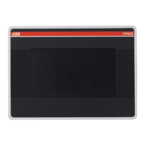
Introduction The operational guidelines described below is information which relates to the device, place of employ- ment, transportation, storage, assembly, use and maintenance. This Operating Instruction describes the main features of the CP600 Control Panels. The Operating In- structions refers to the following models: Picture Type Description... -
Page 4: Before You Start
Before You Start Safety Notices Indicates an imminent risk. It will lead to death or serious injury if not avoided. DANGER! Indicates a possible risk. It may lead to death or serious injury if not avoided. WARNING! Indicates a possible risk. It may lead to light or slight injury or material damage if not avoid- CAUTION! Markups Enumeration. -
Page 5: Product Overview
Product Overview The Control Panels combine state-of-the-art features and top performance with an outstanding design. They are the ideal choice for all demanding HMI applications including factory and building automation. These Control Panels have been designed to run the PB610 Panel Builder 600 software. PB610 Panel Builder 600 Runtime included. -
Page 6: Standards And Approvals
Standards and Approvals The Control Panels have been designed for installation and use in an industrial environment in compli- ance with the 2004/108/EC EMC Directive. The products have been designed in compliance with: EN 61000-6-4:2007+A1:2011 EN 55011 Class A EN 61000-6-2:2005 EN 61000-4-2 EN 61000-4-3 EN 61000-4-4... -
Page 7: Technical Specifications
Technical Specifications Parameter Value Touchscreen technology Resistive Back-up battery 3V 50mAh Lithium, rechargeable, not user-replaceable, model VL2330 Fuse Automatic Serial Port RS-232, RS-485, RS-422 software configurable User memory Flash 128 MB for CP620, CP630, CP635 including –x, -x-WEB Flash 256 MB for CP635-Fx, Flash 256 MB for CP651, CP661, CP665, CP676 including –x, -x-WEB Recipe memory Flash... -
Page 8: Cp635-Fx
CP635-Fx: Main Features Stainless steel bezel 316/1.440l Food-compatible gasket Food standard sealing compliant with FDA 21 CFR 177.2006 PCAP touchscreen, can be operated with gloves for food areas Designated according to DIN EN 1672-2 Designated according to the EHEDG Guideline Chemical Resistance Protective front foils are made with high-quality polyester. -
Page 9: Electromagnetic Compatibility (Emc)
Electromagnetic Compatibility (EMC) Test executed on the 230 V AC side of the Power Supply (EN 61000-4-11). Parameter Value According to Radiated disturbance test Class A EN 55011 Electrostatic discharge im- 8 kV (air electrostatic discharge) EN 61000-4-2 munity test 4 kV (contact electrostatic discharge) Radiated, radio-frequency, 80 MHz …... -
Page 10: Durability Information
Durability Information Parameter Value of CP600 Value of CP635-Fx Backlight service life MTBF value: 40,000 h (LED type) (time of continuous operation until the brightness of the backlight reaches 50 % of the rated value when the surrounding temperature reach 25 °C), Battery lifetime 10 years if the surrounding temperature is 25 °C 5 years if the surrounding temperature is 40 °C... -
Page 11: Technical Data
Technical Data Model CP620-x (-WEB) CP630-x (-WEB) Display/Backlight TFT Color / LED TFT Color / LED Colors 64 K 64 K Resolution 480 x 272 320 x 240 Diagonal (inches) 4.3” 5.7“ Dimming Touchscreen User memory flash 128 MB 128 MB SC card slot Recipe memory Yes. - Page 12 Model CP635-Fx CP635-x (-WEB) Display/Backlight TFT Color / LED TFT Color / LED Colors 64 K 64 K Resolution 800 x 480 800 x 480 Diagonal (inches) 7“ widescreen 7“ widescreen Dimming Touchscreen User memory flash 256 MB 128 MB SC card slot Recipe memory Yes.
- Page 13 Model CP651-x(-WEB) CP661-x(-WEB) Display/Backlight TFT Color / LED TFT Color / LED Colors 64 K 64 K Resolution 800 x 600 800 x 600 Diagonal (inches) 10.4” 12.1“ Dimming Touchscreen User memory flash 256 MB 256 MB SC card slot Recipe memory Yes.
- Page 14 Model CP665-x(-WEB) CP676-x(-WEB) Display/Backlight TFT Color / LED TFT Color / LED Colors 64 K 64 K Resolution 1280 x 800 1024 x 768 Diagonal (inches) 13.3” 15“ Dimming Touchscreen User memory flash 256 MB 256 MB SC card slot Recipe memory Yes.
-
Page 15: Dimensions
Dimensions CP620 CP630, CP635, CP651, CP661, CP665, CP676 including –x(-WEB) including –x(-WEB), CP635-Fx Model inches inches inches inches inches inches CP620-x(-WEB) 5.35” 3.78” 2.05” 4.21” 5.78” 0.16” CP630-x(-WEB) 6.93” 5.35” 1.85” 5.79” 7.36” 0.16” CP635-x(-WEB) 6.93” 5.35” 1.85” 5.79” 7.36” 0.16”... -
Page 16: Installation Environment
Installation Environment The equipment is not intended for continuous exposure to direct sunlight. This might accelerate the aging process of the front panel film. The equipment is not intended for installation in contact with corrosive chemical compounds. Check the resistance of the front panel film to a specific compound before installation. Do not use tools of any kind (screwdrivers etc.) to operate the touchscreen of the panel. -
Page 17: Installation Procedure
Installation Procedure Place the fixing brackets. Screw each fixing screw until the bezel corner gets in contact with the panel. CAUTION! CP620, CP630, CP635, CP651, CP661, CP665, CP676... - Page 18 Communication Cables The communication cable must be chosen for the type of device being connected. Connection to an AC-500 with the TK681 CP600-AC500 RS232 communication cable Connection to an AC-500(-eCo) with the TK682 CP600-AC500-eCo RS485 communication cable *) all resistors: 0.25 W Shield SubD9 male CP620, CP630, CP635, CP651, CP661, CP665, CP676...
-
Page 19: Connections
Connections Serial port USB port Expansion slot for plugin module 2x Ethernet port Power supply connector SD card slot Serial port 2x USB port 2x Expansion slot for plugin modules 2x Ethernet port Power supply connector SD card slot CP620, CP630, CP635, CP651, CP661, CP665, CP676... -
Page 20: Serial Port
Serial Port The serial port is used to communicate with the PLC or with another type of controller. Different electrical standards are available for the signals in the PLC port connector: RS-232, RS-422, RS-485. It is always necessary to use the correct cable type to connect on the PLC. If the proper cable is not used, communication with the PLC will not be possible. -
Page 21: Power Supply, Grounding And Shielding
Power Supply, Grounding and Shielding DC Power Connector, Female - R/C Terminal Blocks (XCFR2), manufactured by Weidmüller Inc., Cat. No. BLZ 5.08, torque 4.5 lb-in Ensure that the power supply has enough power capacity for the operation of the equipment. NOTE The unit must always be grounded to earth. -
Page 22: Battery
Battery The Control Panels are equipped with a rechargeable lithium battery, not user-replaceable. The battery maintains the hardware real-time clock (date and time). Charging the Battery At first installation recharge the battery for 48 h. When the battery is charged, it assures a period of 3 month of data back-up at 25 °C. CP620-x(-WEB) CP630, CP635, CP651, CP661, CP665, CP676 including –x(-WEB) versions The battery must not be disposed as unsorted domestic waste. -
Page 23: Cleaning Faceplates
Cleaning Faceplates The equipment must be cleaned only with a soft cloth and neutral soap product. Do not use solvents. CP620, CP630, CP635, CP651, CP661, CP665, CP676... -
Page 24: Getting Started
Getting Started The Control Panels (CP6xx-x, not CP6xx-x-WEB versions) must be programmed with the programming package PB610 Panel Builder 600. The Control Panels are programmed via the Ethernet interface. The Control Panel must be in configuration mode to be programmed. ... -
Page 25: System Settings
System Settings The Control Panels have a system settings tool to allow basic and preliminary settings to the unit. System settings tool The system settings tool is a rotating menu. Use the navigation buttons Next and Back to scroll between the available options. ... - Page 26 System Mode System Mode is the complete interface of the system settings tool where all options are available. Additionally to the options of the User Mode the following options are available: Format Flash: allows to format the internal panel flash disk ...
-
Page 27: Dedicated Led Indicators
Dedicated LED Indicators There is one LED in the upper left part of the front below the red stripe. The meaning of the LED indicator is explained in the following table: LED color Status Meaning Green Normal Operation Communication error or alarm requires acknowledgement Blinking Hardware fault or battery low CP620, CP630, CP635, CP651, CP661, CP665, CP676... -
Page 28: Unpacking And Packing Instructions
Unpacking and Packing Instructions To repack the unit follow the instructions backwards. CP620, CP630, CP635, CP651, CP661, CP665, CP676... - Page 29 Eppelheimer Straße 82 3520 Farum contents of this document without prior notice. With regard to 69123 Heidelberg, Germany purchase orders, the agreed particulars shall prevail. ABB AG Denmark Phone: +49 62 21 701 1444 does not accept any responsibility whatsoever for potential...